Abstract
Selecting resonance parameters alone does not establish an efficient operating regime for a vibration-driven robot. This numerical study formulates the joint optimization of mean transport speed and combined root-mean-square drive torque for two sliding modules with unbalanced rotors. A hybrid dry-friction model includes normal-load modulation and inverse rotor torques. Analytical contact-capacity and torque bounds constrain six dimensionless design variables. A reproducible search is checked using an independent event-driven solver. For an illustrative 0.55 kg system, a 9 mN m torque-budget design increases mean speed from 0.0641 to 0.1336 m/s while reducing RMS torque by 14.3 %. The highest-speed design found reaches 0.4078 m/s at 30.95 mN m. The results distinguish contact admissibility, resonance tuning and drive loading; all reported gains concern the stated numerical model and parameter bounds.
1. Introduction
Vibration-driven locomotion converts periodic internal motion into displacement through interaction with the supporting surface. For two spring-connected modules with unbalanced rotors, Zimmermann et al. [1] established the influence of excitation phase and resonance detuning on velocity under small dry friction. Stiffness selection and phase adjustment were subsequently studied in a two-mass system [2], while numerical and multibody simulations examined a wheeled configuration [3].
Related implementations include a wheeled robot with a crank-slider vibro-impact mechanism, for which impact-gap selection was investigated to increase average speed [4], and an in-pipe robot combining an unbalanced rotor with overrunning clutches [5]. These studies demonstrate how excitation parameters and directional constraints influence vibration-driven transport.
Multi-objective optimization is established in this field. Diao et al. [6] optimized average and backward velocities, whereas Xue et al. [7] considered the velocity-nergy compromise. Sliding bifurcations complicate dry-friction dynamics [8]. Complementary approaches include optimal control of multi-module robots [9] and phase coordination for maximum steady-state speed with linear or nonlinear connections [10]. Amiri et al. [11] investigated parameter optimization and motion control of two spring-connected blocks excited by one unbalanced rotor, considering average velocity and energy consumption. More recent optimal-control formulations include general actuation histories [12].
Du et al. [13] experimentally classified stick-slip locomotion regimes, supporting explicit treatment of frictional switching. Chen and Xu [14] demonstrated two-module locomotion using a passive position limiter and controlled internal masses, while Zhao et al. [15] exploited bistable intermodule coupling to improve locomotion. For a vibro-impact capsule, Liu et al. [16] found that the fastest and most energy-efficient operating settings differ. Liu’s recent review [17] emphasizes contact laws, switching sequences and attractor structure in performance assessment. These studies motivate joint evaluation of excitation, coupling and contact dynamics; the present formulation specifically targets the speed–RMS-drive-torque compromise for constant-speed unbalanced rotors.
The contribution of this study is a joint mechanical and excitation design formulation for two constant-speed unbalanced rotors, with mean speed and combined RMS drive torque as competing objectives. Inverse rotational dynamics links locomotion to drive loading, while normal-load modulation, sticking and a prescribed contact reserve define admissibility. Six dimensionless variables describe mass and unbalance allocation, excitation intensity, frequency tuning, damping and phase. Contact-capacity and energy-based torque bounds provide independent consistency checks. The resulting numerical improvements are conditional on the stated model and parameter bounds.
2. Mathematical model and analytical bounds
Two modules slide on a horizontal plane (Fig. 1). Vertical translation and pitch are suppressed; contact is admissible only while both normal reactions remain positive. Each total module mass includes an eccentric mass with radius and static moment . The spring deformation is , and denotes viscous damping. Both rotors turn counterclockwise at the prescribed speed , with and . The horizontal equations are:
Fig. 1Translationally constrained modules with vertical-plane rotors and spring-damper coupling
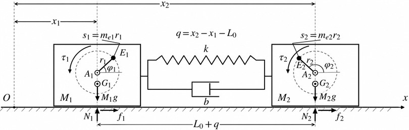
The reaction and sliding-friction law are given by Eq. (2). At zero velocity the module sticks with while , where is the right-hand side of Eq. (1) excluding friction. Otherwise, it starts sliding in the direction of . Static friction therefore cannot be represented by simply setting the sign function to zero. Therefore, we obtain:
For an eccentric position , where is the constant height of rotor axis above the supporting plane, inverse rotational dynamics gives Eq. (3). Bearing and electrical losses are excluded here. The acceleration term vanishes at imposed constant speed; independent rotor polar inertia is consequently not an effective steady-state design variable:
A momentum check distinguishes transport from initialization drift. With and , the complete-system centre of mass is . Thus:
In the frictionless limit is constant and cycle-mean motion is , independent of stiffness and damping. In particular, initializing stationary platforms with already-spinning rotors generally assigns a nonzero . The present optimization instead evaluates converged frictional motion. Useful travel is defined along negative , so its mean speed is .
Two analytical results restrict the design. Define , , and . A contact reserve gives:
The largest contact-limited frequency is attained when , with equal specific unbalance . This condition optimizes contact capacity; transport speed also depends on frictional dynamics. For a periodic sliding regime, spring and kinetic energies return to their initial values. With angle brackets denoting cycle averaging, define the combined drive demand and obtain:
Cauchy–Schwarz gives . Since periodic implies equal mean module velocities and for , a necessary lower bound follows:
Equality is not asserted: velocity reversals and oscillating torques generally make this bound conservative. It nevertheless provides a mechanical consistency check independent of the optimizer.
3. Optimization formulation and numerical procedure
The remaining variables describe frequency tuning and damping. With reduced mass , let and . The six-dimensional design vector and dimensional reconstruction are:
The illustrative study fixes 0.55 kg, 1.5×10⁻³kg·m, 0.03 m and 9.81 m/s2. Thus and each remaining body mass is . The assumed, unmeasured friction coefficients are 0.35 and 0.30. The search bounds are:
Admissible designs satisfy Eq. (5) with 0.10, 0.04 m and 0.08 N·m for each drive. These stroke and torque limits are design assumptions, not ratings of a tested prototype. The objectives are and ; with denoting the admissible set, a torque-budget formulation is:
A 2048-point Sobol sample initialized the search. Differential evolution (72 individuals, up to 160 generations, two seeds) then maximized speed without an RMS cap and under eleven budgets from 7 to 30 mN∙m. Feasible nondominated candidates form an approximate Pareto set. The screening solver uses explicit stick-slip transitions and fixed time steps. Finalists were refined to 8192 steps per revolution and independently recomputed with event-driven integration (2×10⁻⁹, 2×10-11). The final averages use 20 cycles after 200 transient cycles. The supplementary archive specifies the search seeds, solver settings and full-precision parameters.
4. Results and discussion
Fig. 2 shows the computed trade-off and a frequency–phase section of the design space. The reference B uses equal masses and unbalances, 0.60, 0.96, 0.08 and antiphase excitation. It is a contact-admissible resonance-oriented comparator, rather than the contact-incompatible 25 Hz example of [2]. C is a selected 9 mN·m torque-budget solution; is the highest-speed design found. Their parameters and event-solver results are listed in Table 1.
Fig. 2Computed trade-off and a frequency-phase section of the design space (Gray areas violate the adopted constraints)
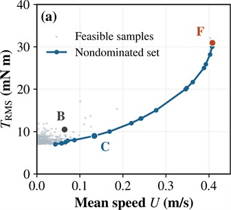
a) Feasible samples and approximate Pareto set
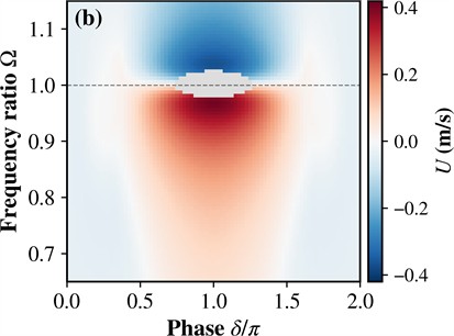
b) Speed section at 0.5, 0.8, 0.03
Compared with B, C increases speed by 108.25 % and reduces combined RMS torque by 14.34 %. The optimum found for this budget is nearly mass-balanced and antiphase, but its frequency ratio is 0.794 rather than 0.96. The joint retuning raises stiffness to 628.3 N/m and lowers damping; maximum spring deformation decreases from 11.53 to 8.57 mm. Fig. 3 compares the velocity and drive-torque waveforms. The available improvement therefore involves changing excitation intensity, tuning and damping together.
reaches 0.407812 m/s, with 30.9466 mN·m and 35.96 mm maximum deformation. Its frequency ratio returns close to resonance, while modestly unequal mass and unbalance allocations exploits the normal-load modulation. The second module approaches the 10 % contact reserve, whereas the 80 mN∙m peak limit remains inactive. Both C and F lie near the upper excitation bound and lower damping bound; these are conditional design recommendations, not universal optima or evidence that zero damping is desirable.
Table 1Design parameters and steady-state numerical performance
Quantity | Reference B | Compromise C | Fastest found F |
0.50000 | 0.50077 | 0.52821 | |
0.50000 | 0.49968 | 0.46926 | |
0.60000 | 0.80000 | 0.80000 | |
0.96000 | 0.79355 | 0.96779 | |
0.08000 | 0.03003 | 0.03000 | |
(degrees) | 180.000 | 179.500 | 180.598 |
(rad/s) | 46.4564 | 53.6431 | 53.6433 |
(N/m) | 321.997 | 628.318 | 421.103 |
(N∙s/m) | 1.06463 | 0.55822 | 0.45583 |
(m/s) | 0.064136 | 0.133563 | 0.407812 |
(mN∙m) | 10.5014 | 8.9950 | 30.9466 |
Peak drive torque (mN∙m) | 11.965 | 11.420 | 42.590 |
Maximum deformation (mm) | 11.529 | 8.572 | 35.961 |
Minimum contact reserve | 0.4000 | 0.1983 | 0.1000 |
(J/m) | 8.314 | 3.032 | 4.535 |
Fig. 3Results of numerical modeling for two steady cycles (T=2π/ω)
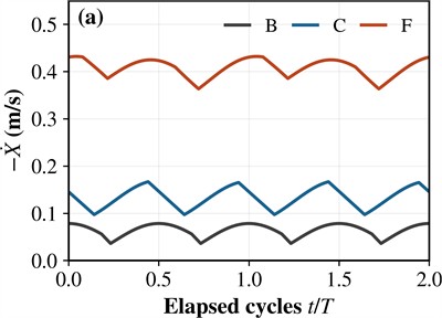
a) Useful instantaneous velocity for B, C and F
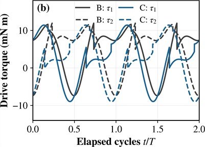
b) Signed moments of both drives for B and C
For an ideal drive receiving no energy credit during braking, define . This mechanical supply metric decreases from 8.314 J/m in B to 3.032 J/m in C (63.53 %), but rises to 4.535 J/m in F. Thus, the speed-maximizing design is not the most economical of the three; electrical efficiency and bearing losses would be additional contributions.
Independent integration changes the tabulated mean speeds by less than 0.00002 % and combined RMS torques by less than 0.006 % relative to the 8192-step solver. The event-driven mean-power balance closes within 4×10⁻⁶ relative error. For each design, the velocities, spring deformation and drive torques repeat after one rotor revolution, and seven tested initial states converge to the same respective cycle. The analytical torque bounds are satisfied. Scaling both friction coefficients by ±10 % changes C speed to 0.1318-0.1353 m/s; however, its upper-friction RMS moment becomes approximately 9.019 mN∙m. Hence, nominal feasibility at 9 mN∙m is not a robust torque guarantee.
The study excludes lift-off, pitch, guide friction, rotor speed ripple and actuator saturation. The illustrative friction coefficients require identification for a prototype. Near-contact operation and the lower damping bound warrant experimental assessment. The plotted Pareto set represents the search performed, not a proof of global optimality.
5. Conclusions
A constrained framework has been developed for selecting mass distribution, unbalance allocation, stiffness, damping and excitation parameters. Proportional allocation of module masses and unbalance static moments maximizes contact-limited excitation capacity. The energy balance supplies a necessary lower bound on combined RMS drive torque. These bounds constrain admissible designs but do not independently determine maximum locomotion speed.
In the numerical example, the selected design achieves 0.1336 m/s with a combined RMS torque of approximately 9 mN∙m. Relative to the feasible reference, speed increases by 108.25 %, RMS torque decreases by 14.34 %, and positive mechanical input energy per travelled distance decreases by 63.53 %. The highest-speed solution found reaches 0.4078 m/s but requires substantially greater torque and relative stroke.
The results support joint selection of excitation frequency, phase difference and mechanical parameters under explicit contact and actuator constraints. At fixed module masses and unbalance static moments, rotor polar inertia does not independently affect inverse torque under prescribed constant speed; its direct contribution arises with angular acceleration. The numerical conclusions apply to the specified parameter bounds and assumed friction coefficients. Experimental friction identification and validation of drive losses and contact conditions remain necessary.
References
-
K. Zimmermann, I. Zeidis, N. Bolotnik, and M. Pivovarov, “Dynamics of a two-module vibration-driven system moving along a rough horizontal plane,” Multibody System Dynamics, Vol. 22, No. 2, pp. 199–219, May 2009, https://doi.org/10.1007/s11044-009-9158-2
-
V. Korendiy, “Substantiation of parameters and motion modelling of two-mass mobile vibratory system with two unbalanced vibration exciters,” Industrial Process Automation in Engineering and Instrumentation, Vol. 52, pp. 16–31, 2018, https://doi.org/10.23939/istcipa2018.52.016
-
V. Korendiy, R. Predko, O. Kotsiumbas, V. Lozynskyy, I. Nazar, and M. Ostashuk, “Substantiating the excitation conditions of a two-module vibration-driven locomotion system with two unbalanced rotors,” Vibroengineering Procedia, Vol. 49, pp. 16–22, May 2023, https://doi.org/10.21595/vp.2023.23329
-
V. Korendiy et al., “Motion simulation and impact gap verification of a wheeled vibration-driven robot for pipelines inspection,” Vibroengineering Procedia, Vol. 41, pp. 1–6, Apr. 2022, https://doi.org/10.21595/vp.2022.22521
-
V. Korendiy, O. Kotsiumbas, V. Borovets, V. Gurey, and R. Predko, “Mathematical modeling and computer simulation of the wheeled vibration-driven in-pipe robot motion,” Vibroengineering Procedia, Vol. 44, pp. 1–7, Aug. 2022, https://doi.org/10.21595/vp.2022.22832
-
B. Diao, X. Zhang, H. Fang, and J. Xu, “Bi-objective optimization for improving the locomotion performance of the vibration-driven robot,” Archive of Applied Mechanics, Vol. 91, No. 5, pp. 2073–2088, Jan. 2021, https://doi.org/10.1007/s00419-020-01870-5
-
J. Xue, S. Zhang, and J. Xu, “Coordinated optimization of locomotion velocity and energy consumption in vibration-driven system,” Meccanica, Vol. 58, No. 2-3, pp. 371–385, Feb. 2022, https://doi.org/10.1007/s11012-022-01488-7
-
H. Fang, Y. Zhao, and J. Xu, “Steady-state dynamics and discontinuity-induced sliding bifurcation of a multi-module piecewise-smooth vibration-driven system with dry friction,” Communications in Nonlinear Science and Numerical Simulation, Vol. 114, p. 106704, Jul. 2022, https://doi.org/10.1016/j.cnsns.2022.106704
-
B. Diao, X. Zhang, H. Fang, and J. Xu, “Optimal control of the multi-module vibration-driven locomotion robot,” Journal of Sound and Vibration, Vol. 527, p. 116867, Feb. 2022, https://doi.org/10.1016/j.jsv.2022.116867
-
Y. Zhao, H. Fang, and J. Xu, “Dynamics and phase coordination of multi-module vibration-driven locomotion robots with linear or nonlinear connections,” Meccanica, Vol. 58, No. 2-3, pp. 509–535, Jan. 2023, https://doi.org/10.1007/s11012-022-01623-4
-
N. Amiri, K. Sohrabi, G. Eftekharian, and V. Fakhari, “Optimization and control of an energy-efficient vibration-driven robot,” Journal of Vibration and Control, Vol. 30, No. 9-10, pp. 2184–2199, May 2023, https://doi.org/10.1177/10775463231175543
-
B. Diao, X. Zhang, and J. Xu, “The optimal control methodology based on normalized Gaussian functions for vibration-driven locomotion robots,” Multibody System Dynamics, Vol. 64, No. 1, pp. 85–104, Jun. 2024, https://doi.org/10.1007/s11044-024-09994-0
-
Z. Du, H. Fang, X. Zhan, and J. Xu, “Experiments on vibration-driven stick-slip locomotion: A sliding bifurcation perspective,” Mechanical Systems and Signal Processing, Vol. 105, pp. 261–275, Dec. 2017, https://doi.org/10.1016/j.ymssp.2017.12.001
-
Q. Chen and J. Xu, “Locomotion of two vibration-driven modules connected by a mechanical position limiter,” International Journal of Mechanical Sciences, Vol. 137, pp. 252–262, Jan. 2018, https://doi.org/10.1016/j.ijmecsci.2018.01.027
-
Y. Zhao, H. Fang, B. Diao, X. Zhang, and J. Xu, “Exploiting the bistable dynamics in a two-module vibration-driven robot for locomotion performance enhancement,” Journal of Sound and Vibration, Vol. 544, p. 117387, Oct. 2022, https://doi.org/10.1016/j.jsv.2022.117387
-
Y. Liu, S. Islam, E. Pavlovskaia, and M. Wiercigroch, “Optimization of the Vibro-Impact capsule system,” Strojniški Vestnik – Journal of Mechanical Engineering, Vol. 62, No. 7-8, pp. 430–439, 2016, https://doi.org/10.5545/sv-jme.2016.3754
-
Y. Liu, “Non-smooth dynamics of vibration-driven robots: A review,” International Journal of Non-linear Mechanics, Vol. 188, p. 105377, Apr. 2026, https://doi.org/10.1016/j.ijnonlinmec.2026.105377
About this article

The authors have not disclosed any funding.
The datasets generated during and/or analyzed during the current study are available from the corresponding author on reasonable request.
The authors declare that they have no conflict of interest.

