Abstract
A numerical design study compares a wheeled crank-driven robot in non-impact and compliant-impact operation under common drive-load constraints. Exact slider-crank kinematics, finite link inertia and a unilateral wheel constraint are retained in a coupled model. An energy balance bounds the attainable mean speed, while a constrained search adjusts internal mass, suspension stiffness and damping, crank radius, frequency and clearance. Six root-mean-square torque budgets define numerical approximations of the speed–torque trade-off. At a 0.20 N∙m budget, the best feasible solutions found achieve 0.4433 m/s without impacts and 0.5157 m/s with impacts, a 16.3 % increase. Their peak torques are 0.354 and 0.357 N∙m. However, positive shaft work per distance rises by 8.1 % in the impact solution. Thus, impacts improve attainable speed in the investigated domain without necessarily improving energy economy. The results are computational and conditional on stated contact, resistance and drive assumptions.
1. Introduction
Internal actuation can produce directed locomotion through interaction with a resistive environment. Fang and Xu optimized excitation timing to maximize the mean steady-state velocity of a two-module vibration-driven system [1]. For a vibro-impact capsule, Liu et al. showed that maximum progression and minimum energy consumption require different parameter choices [2]; subsequent experiments verified the capsule model while varying support stiffness and excitation frequency and amplitude [3]. For wheeled crank-driven systems, earlier studies established a locomotion model and optimized pre-impact velocities [4], simulated impact clearances [5], and measured kinematic characteristics experimentally [6]. Further work examined gap-dependent performance [7] and developed remote control of excitation [8]. Multi-objective approaches balance mean and backward velocities [9], coordinate speed and energy consumption [10], and consider impact force and energy under friction uncertainty [11]. Amiri et al. optimized a two-module robot with an unbalanced rotor and assessed speed, energy demand and control effort [12].
The present study addresses whether compliant impacts increase attainable mean speed when crank-driven designs are optimized under common RMS and peak torque limits. Exact slider-crank kinematics and finite moving-link inertia are combined with unilateral contact and one-way rolling. Mass allocation, suspension stiffness and damping, crank radius, frequency and clearance are selected to maximize steady mean speed under RMS torque and peak-load constraints. A passive energy balance provides an analytical consistency bound. The specific contribution is a torque-constrained comparison of non-impact and compliant-impact designs that retains finite moving-link inertia and quantifies the associated speed-energy trade-off.
2. Mathematical model
The system in Fig. 1 consists of a wheeled chassis, one internal translating mass and a crank-slider exciter coupled through a spring and damper. A compliant stop acts on the internal mass; overrunning clutches prevent backward chassis motion. The total physical mass remains fixed during mass redistribution. Horizontal motion is considered; wheel rotational inertia, wheel slip and guide friction are neglected. The ideal speed-controlled drive maintains and can absorb returned mechanical power.
Fig. 1Kinematic scheme with external forces acting on the entire robot (left) and free-body diagram of the internal mass (right)
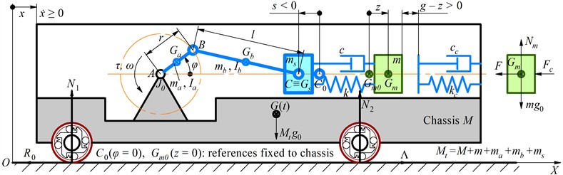
Let be the absolute chassis displacement and the internal displacement relative to the chassis, measured from the initial undeformed-spring configuration at . The slider displacement is retained exactly:
For suspension extension and stop penetration , the coupling and contact forces are:
where is the Heaviside function. Contact damping acts only during compression, giving a non-tensile passive contact law. It is a stated constitutive assumption, not an identified rubber model. Put and . The kinetic energy, including finite moving-link inertia, is:
For crank, rod and slider masses indexed by , the inertia coefficients are:
Primes denote derivatives with respect to . The centers of mass relative to the chassis are , and . Uniform crank and rod inertias are and ; their angular derivatives are 1 and . The slider has no rotation. Thus moving drive masses are counted once in , with additional velocity coupling through and .
Lagrange equations and inverse dynamics give:
The unilateral constraint is , , . At rest, the chassis remains blocked when its free acceleration would be negative; otherwise it is released. denotes the assumed forward rolling resistance. The moving links rotate in a vertical plane, so , with 9.81 m/s2. The stop force affects the crank through the coupled response; it is not added again to the last term of Eq. (5). A constant rotor inertia does not change the required torque at prescribed constant speed.
3. Optimization and numerical procedure
A settled averaging window spans an integer number of crank periods. The mean speed, root-mean-square torque and positive mechanical work per travelled distance are:
The parameter vector is , where . Instead of assigning arbitrary weights to speed and torque, each mode is searched under successive torque budgets:
The domains and retain settled period-one states reached from zero translational initial conditions at imposed crank speed. All load and travel limits apply only to the settled averaging window. Mode N has no contact; mode I requires contact opening and closure within the settled response. The admissible ranges are 0.3-1.2 kg, 300-2000 N/m, 1-12 N∙s/m, 15-30 mm, 3-10 Hz and 0-40 mm. For N, the stop is removed and the same travel limits are imposed. The six torque budgets are 0.05, 0.10, 0.15, 0.20, 0.25 and 0.30 N∙m. Equal torque limits at variable frequency do not imply equal power limits.
The illustrative reference values 4.3 kg, 0.6 kg, 800 N/m, 104 N/m, 25 mm, 80 mm, 6 Hz and 4 mm follow the numerical configuration in [7]. Additional assumptions are 4 N∙s/m and 0.4 N. Moving-link masses are 0.06 kg, 0.10 kg and 0.08 kg; the rotor inertia is 8×10⁻⁵ kg∙m2. The chassis mass is . The drive and damping parameters are not experimental identifications. The reference case is therefore an adapted numerical baseline, not an experimental validation against [7]. Contact parameters and rod length remain fixed in the main search.
For passive contact and ideal clutch action, the settled energy balance supplies a necessary analytical bound:
where, , and the ideal clutch performs no work because . The stored energy contains Eq. (3), the suspension energy, the stop energy and the gravitational energy of the moving links. Eq. (8) follows when their net change over the averaging window vanishes. It constrains achievable speed but does not locate the optimum. In particular, maximizing an isolated pre-impact velocity is not equivalent to maximizing long-time locomotion.
The equations are integrated by fixed-step fourth-order Runge-Kutta with unilateral acceleration enforcement and a velocity projection that preserves the internal absolute velocity when the chassis is stopped. This is not an exact event-location method. Initial translational coordinates and velocities are zero, while crank speed is imposed. Only settled period-one responses are retained. Each mode uses 2048 scrambled Sobol samples (seed 20260916), followed at each budget by seeded differential evolution (up to 75 generations) and four bounded Nelder-Mead refinements. Search runs use 700 steps per revolution, 70 settling revolutions and 10 averaging revolutions. Feasibility is polished and checked at 2000, 4000 and 8000 steps per revolution; final values discard 220 revolutions and average 12. Periodicity is checked for at consecutive zero-phase crossings using where 0.1 m/s and the maximum is taken over the averaging window. The drifting coordinate is excluded. The resulting front is a numerical approximation, not a proof of global optimality.
4. Results and discussion
Fig. 2 compares the best feasible period-one solutions found in the stated domain. At 0.05 N∙m, mean speed is 0.1481 m/s without impacts and 0.2098 m/s with impacts, a 41.7 % advantage. At 0.30 N∙m, the corresponding speeds are 0.5532 and 0.6182 m/s, reducing the advantage to 11.8 %. The relative benefit therefore decreases overall, with a small local increase between 0.10 and 0.15 N∙m. These comparisons concern equal admissible RMS torque, common peak limits and the same parameter bounds, rather than equal frequency or input power.
Fig. 2Numerical approximations of attainable performance (Lines connect computed budgets)
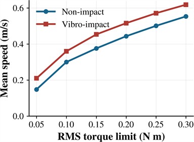
a) Best feasible speed at each RMS torque budget
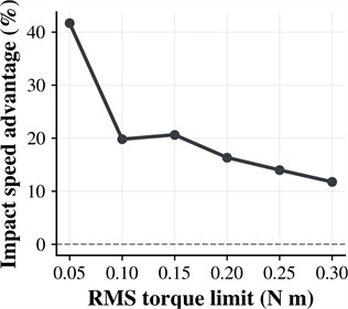
b) Relative speed difference of impact and non-impact solutions
Table 1 gives a representative pair at a common 0.20 N∙m RMS budget. The impact solution is 16.3 % faster while its peak torque differs by only 0.69 %. Its contact force is 99.90 N, close to the 100 N limit. The reference impact design has an RMS torque of 0.20009 N∙m and lies slightly above this exact budget. Removing the reference stop gives a computed RMS torque of 1.127 N∙m and displacement range approximately –143 to 90 mm, violating both torque and travel limits.
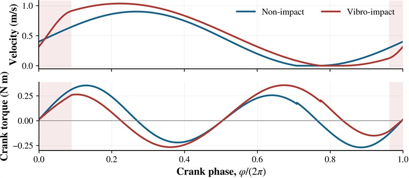
The selected designs allocate approximately 1.19 kg to the internal body and use a crank radius near the 15 mm lower bound. Their suspension damping is close to the 1 N∙s/m lower bound. The impact design uses a lower stiffness (841.8 versus 911.4 N/m), but a higher frequency (5.233 versus 4.473 Hz). Its 30.01 mm gap allows acceleration before contact, while the compliant stop and wheel constraint redistribute motion through the cycle (Fig. 3). Contact occupies 12.74 % of a revolution; the force and positive travel limits are nearly active. These are boundary-dependent parameter selections, not universal optimum masses or clearances.
Table 1Reference configuration and selected solutions under a common RMS torque budget
Quantity | Reference I | Selected N | Selected I |
(kg) | 0.600 | 1.193 | 1.194 |
(N/m) | 800.0 | 911.4 | 841.8 |
(N∙s/m) | 4.000 | 1.004 | 1.114 |
(mm) | 25.00 | 15.00 | 15.04 |
(Hz) | 6.000 | 4.473 | 5.233 |
(mm) | 4.00 | – (stop removed) | 30.01 |
(m/s) | 0.2566 | 0.4433 | 0.5157 |
(N∙m) | 0.2001 | 0.1985 | 0.1997 |
(N∙m) | 0.393 | 0.354 | 0.357 |
(N) | 94.75 | 0.00 | 99.90 |
Contact duty (%) | 12.51 | 0.00 | 12.74 |
(J/m) | 15.150 | 6.540 | 7.070 |
Faster progression does not imply lower work per distance. At the selected budget, increases from 6.540 to 7.070 J/m (8.1 %), despite the speed benefit. An energy-oriented design could therefore favor another point or the non-impact regime. Increasing resolution from 4000 to 8000 steps per revolution changes speed by less than 0.0010 %, RMS torque by less than 0.0043 %, and peak torque by less than 0.0074 % across the twelve retained solutions. The largest relative energy-balance residual is 0.0025 %. These checks support numerical consistency of the retained branches.
The comparison assumes one-dimensional motion, ideal clutches and a speed-controlled drive capable of braking. The abrupt imposed-speed start exceeds the settled limits; a controlled start-up must be designed before implementation. Contact and motor parameters require experimental identification; wheel inertia, slip, electrical losses and durability are not assessed. Other attractors may coexist. Positive shaft work measures mechanical demand, not battery consumption.
Fig. 3Settled responses of the selected designs: chassis velocity and crank torque. Shading marks contact intervals of the impact design; phase zero is the initial crank orientation
5. Conclusions
A coupled model incorporating exact slider-crank kinematics, finite moving-link inertia, unilateral contact and one-way rolling has been developed for constrained optimization of a wheeled vibration-driven robot. The passive energy balance provides a necessary analytical consistency bound, while the numerical search identifies feasible combinations of internal mass, suspension stiffness and damping, crank radius, excitation frequency and clearance.
Within the investigated domain, compliant impacts increase the best feasible mean speed found at all six RMS torque budgets. The relative gain decreases overall from 41.7 % at 0.05 N·m to 11.8 % at 0.30 N·m. At 0.20 N·m, the selected non-impact and impact designs achieve 0.4433 and 0.5157 m/s, respectively, with comparable peak torques of 0.354 and 0.357 N·m. These comparisons use common torque constraints; equal torque budgets at different excitation frequencies do not imply equal power limits.
The representative designs favor an internal mass near 1.19 kg, a crank radius near 15 mm and suspension damping close to the lower admissible bound. The impact solution combines lower suspension stiffness and higher excitation frequency with a 30.01 mm clearance. Its contact-force and travel limits are nearly active, so the selected parameters depend on the imposed bounds and require practical design margins. At the 0.20 N·m torque budget, the 16.3 % speed gain is accompanied by an 8.1 % increase in positive shaft work per distance, from 6.540 to 7.070 J/m. Thus, the preferred operating regime depends on the balance between attainable speed and energy demand.
References
-
H.-B. Fang and J. Xu, “Controlled motion of a two-module vibration-driven system induced by internal acceleration-controlled masses,” Archive of Applied Mechanics, Vol. 82, No. 4, pp. 461–477, Jul. 2011, https://doi.org/10.1007/s00419-011-0567-3
-
Y. Liu, M. Wiercigroch, E. Pavlovskaia, and H. Yu, “Modelling of a vibro-impact capsule system,” International Journal of Mechanical Sciences, Vol. 66, pp. 2–11, Oct. 2012, https://doi.org/10.1016/j.ijmecsci.2012.09.012
-
Y. Liu, E. Pavlovskaia, and M. Wiercigroch, “Experimental verification of the vibro-impact capsule model,” Nonlinear Dynamics, Vol. 83, No. 1-2, pp. 1029–1041, Sep. 2015, https://doi.org/10.1007/s11071-015-2385-6
-
V. Korendiy, V. Gursky, O. Kachur, P. Dmyterko, O. Kotsiumbas, and O. Havrylchenko, “Mathematical model and motion analysis of a wheeled vibro-impact locomotion system,” Vibroengineering Procedia, Vol. 41, pp. 77–83, Apr. 2022, https://doi.org/10.21595/vp.2022.22422
-
V. Korendiy et al., “Motion simulation and impact gap verification of a wheeled vibration-driven robot for pipelines inspection,” Vibroengineering Procedia, Vol. 41, pp. 1–6, Apr. 2022, https://doi.org/10.21595/vp.2022.22521
-
V. Korendiy, O. Kachur, V. Gursky, V. Gurey, R. Pelio, and O. Kotsiumbas, “Experimental investigation of kinematic characteristics of a wheeled vibration-driven robot,” Vibroengineering Procedia, Vol. 43, pp. 14–20, Jun. 2022, https://doi.org/10.21595/vp.2022.22721
-
V. Korendiy, O. Kachur, V. Gurskyi, and P. Krot, “Studying the influence of the impact gap value on the average translational speed of the wheeled vibration-driven robot,” Engineering Proceedings, Vol. 24, No. 1, p. 25, 2022, https://doi.org/10.3390/iecma2022-12897
-
V. Korendiy, O. Kachur, and R. Predko, “Development of a remote-control system for a mobile vibration-driven robot,” in 17th International Conference on the Experience of Designing and Application of CAD Systems (CADSM), pp. 6–10, 2023, https://doi.org/10.1109/cadsm58174.2023.10076517
-
B. Diao, X. Zhang, H. Fang, and J. Xu, “Bi-objective optimization for improving the locomotion performance of the vibration-driven robot,” Archive of Applied Mechanics, Vol. 91, No. 5, pp. 2073–2088, Jan. 2021, https://doi.org/10.1007/s00419-020-01870-5
-
J. Xue, S. Zhang, and J. Xu, “Coordinated optimization of locomotion velocity and energy consumption in vibration-driven system,” Meccanica, Vol. 58, No. 2-3, pp. 371–385, Feb. 2022, https://doi.org/10.1007/s11012-022-01488-7
-
J. Zhu, M. Liao, Y. Zheng, S. Qi, Z. Li, and Z. Zeng, “Multi-objective optimisation based on reliability analysis of a self-propelled capsule system,” Meccanica, Vol. 58, No. 2-3, pp. 397–419, Apr. 2022, https://doi.org/10.1007/s11012-022-01519-3
-
N. Amiri, K. Sohrabi, G. Eftekharian, and V. Fakhari, “Optimization and control of an energy-efficient vibration-driven robot,” Journal of Vibration and Control, Vol. 30, No. 9-10, pp. 2184–2199, May 2023, https://doi.org/10.1177/10775463231175543
About this article

The authors have not disclosed any funding.
The datasets generated during and/or analyzed during the current study are available from the corresponding author on reasonable request.
The authors declare that they have no conflict of interest.

