Abstract
In this study, an overall simulation model of the power rolling ring, consisting of an outer conductive ring, an inner conductive ring, and a flexible ring, is established using simulation software. A normal refined free quadrilateral mesh is applied to the inner and outer conductive rings, while a finer mesh of the same type is applied to the flexible ring. In the model, H62 brass is selected as the material for the inner and outer conductive rings, and C17200 beryllium bronze is used for the flexible ring. Transient analysis is conducted by defining the rotational speed of the inner conductive ring, the identity boundary pairs at the contact interfaces, and the friction coefficient. The study focuses on investigating the motion trajectory of the power rolling ring and the stress distribution characteristics of the flexible ring under varying widths of 0.6 mm, 0.8 mm, 1 mm, and 1.2 mm. The results indicate that the maximum stress on the flexible ring occurs at its contact positions with the inner and outer conductive rings; furthermore, as the width increases, the maximum stress at the contact points exhibits a trend of initially decreasing and then increasing, and the overall structural motion trajectory of the model proves to be reasonable. This research provides a solid theoretical foundation and an effective methodology for the structural optimization and performance evaluation of power rolling rings.
1. Introduction
As a precision rotating signal transmission component, the power rolling ring achieves twist-free signal and power transmission between rotating and stationary mechanisms through the transmission form of rolling friction. It is widely used in equipment requiring 360° unlimited rotation, such as industrial automation, aerospace, and intelligent security [1]-[2]. Its core working principle involves a fixed outer conductive ring and a rotating inner conductive ring that drives a flexible ring to perform a rolling friction motion between them. As the core moving component, the flexible ring directly determines the contact characteristics, kinematic stability, and overall service life of the power rolling ring, making it a key target for structural design and performance optimization [3].
To improve transmission performance, extensive research has been conducted on the structural design and tribological behavior of rolling ring devices. For instance, optimal design theory has been applied to develop raceway-type flexible rolling ring devices for electrical signal transmission [4]. To meet the high-power and long-life requirements of spacecraft, novel rolling ring modules featuring modularization, multi-rolling friction rollers, and synergistic motion have been developed and experimentally validated [5]-[6]. Furthermore, numerical simulations using ADAMS software have analyzed the pure rolling problem, revealing that sliding occurs between the flexible ring and conductive rings when the static friction coefficient drops to 0.05 [7]. Additionally, current-carrying friction tests have been conducted to investigate the tribological performance and material damage of elastic rings under varying rotational speeds [8].
However, while compliant mechanisms endow the transmission system with excellent adaptability, they inevitably compromise the fundamental in-plane and out-of-plane stiffness of the components. Recent studies indicate that under dynamic load excitation, thin-walled ring structures are highly susceptible to severe meshing deformation and out-of-plane resonance, inducing highly concentrated local bending stresses and high-cycle contact fatigue failure [9]-[10]. Specifically, nonlinear elastic deformation under dynamic excitation is a key factor triggering local bending stress concentration [11], which is precisely the core driver of rolling contact fatigue (RCF) failure at the contact interface [12]. To suppress structural failure, optimizing macroscopic geometric parameters has proven to be an effective means. The finite element method has been successfully employed to evaluate kinematic performance, simulate rolling contact fatigue behavior, and demonstrate the positive impact of structural stiffness on prolonging the service life of high-torque transmission systems incorporating compliant components [13]-[15].
Although existing literature has revealed the positive significance of structural stiffness on service life from a macroscopic dynamics perspective, research remains relatively scarce regarding the specific structure of the power rolling ring. Particularly, there is a lack of systematic exploration into how the single dimensional parameter of “flexible ring width” precisely intervenes in the transient motion trajectory and the dynamic evolution of internal bending stress. In summary, this paper conducts a parameterized transient analysis focusing on the flexible ring width based on multibody dynamics theory. An overall simulation model is established to accurately extract the true motion trajectory and stress response characteristics under different widths. This study aims to deeply reveal the underlying mechanism by which the width parameter influences the redistribution of bending stress and transient contact stability, thereby providing a robust theoretical foundation for the fatigue life evaluation and structural optimization of high-performance power rolling rings.
2. Establishment of simulation model
COMSOL Multiphysics software (version 6.3) is employed to perform the simulation analysis. The actual overall design model of the power rolling ring is illustrated in Fig. 1.
Fig. 1Design model of the power rolling ring: 1 – outer conductive ring; 2 – flexible ring; 3 – idler structure; 4 – inner conductive ring
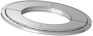
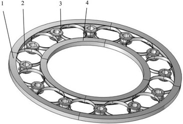
Fig. 1 shows the actual overall design model of the power rolling ring, which is mainly composed of an outer conductive ring, an inner conductive ring, a flexible ring, and an idler structure. During operation, the outer conductive ring remains stationary, while the inner conductive ring continuously rotates and drives the flexible ring to roll between them in the form of rolling friction. The flexible ring undergoes rolling friction at its contact areas with the outer and inner conductive rings, thereby realizing the function of twist-free signal transmission.
Regarding the mesh generation, a free quadrilateral mesh is adopted. Specifically, a normal refined free quadrilateral mesh is applied to the inner and outer conductive rings, while a finer free quadrilateral mesh is applied to the flexible ring, as shown in Fig. 2.
Fig. 2Mesh of the power rolling ring
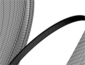
a) Mesh of the inner and outer conductive rings
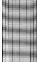
b) Cross-sectional mesh of the flexible ring
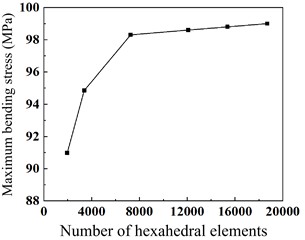
To eliminate the influence of mesh density on the calculation results, a mesh sensitivity analysis was conducted on the flexible ring using the maximum bending stress as the evaluation criterion (with a penalty factor multiplier of 1e-5). As shown in Fig. 3, when the number of hexahedral elements increased from 1,800 to 19,000, the stress value converged after 7,200 elements. To balance computational accuracy and time cost, this refined mesh density was adopted for the global simulation. The final established model of the entire power rolling ring consists of 376,300 domain elements, 70,616 edge elements, and 1,016 vertex elements, with an average element quality of 0.6226, fully ensuring the reliability of the numerical simulation results.
Fig. 3Effect of hexahedral element number on maximum bending stress
3. Numerical analysis and discussion of results
After establishing and meshing the overall simulation model of the power rolling ring, H62 brass is assigned as the material for both the outer and inner conductive rings based on actual conditions, while C17200 beryllium bronze is assigned to the flexible ring, ultimately forming the complete power rolling ring assembly. A rotational speed of 45 r/min is applied to the inner conductive ring, identity boundary pairs are defined at the contact interfaces, and a friction coefficient of 0.1 is specified. A transient analysis is then conducted on the entire model, yielding the following results.
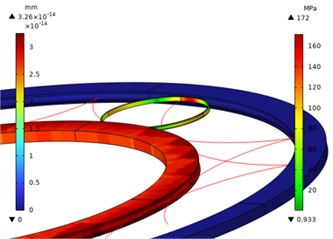
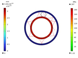
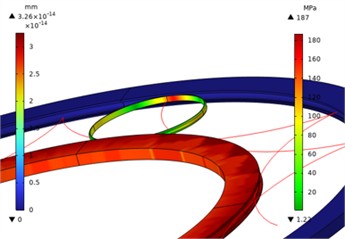
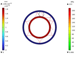
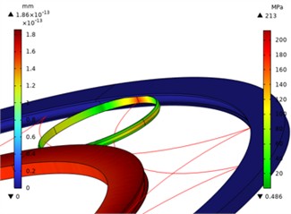
Figs. 4 to 7 show the overall and local stress and displacement contours of the power rolling ring, respectively. Specifically, the contours for the inner and outer conductive rings represent displacement, whereas the contour for the flexible ring represents stress. To prevent visual obstruction, the idlers are hidden in these plots. As can be observed from the figures, the maximum stress on the flexible ring occurs at its contact positions with the inner and outer conductive rings. The red line represents the motion trajectory of a specific point on the flexible ring, indicating that the overall structural motion is reasonable.
Fig. 4Motion trajectory and local stress contour of the power rolling ring with a width of 0.6 mm
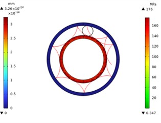
a) Motion trajectory plot
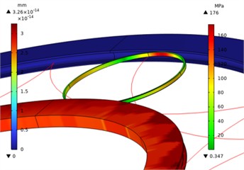
b) Local stress contour plot
Fig. 5Motion trajectory and local stress contour of the power rolling ring with a width of 0.8 mm
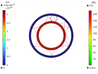
a) Motion trajectory plot
b) Local stress contour plot
Fig. 6Motion trajectory and local stress contour of the power rolling ring with a width of 0.1 mm
a) Motion trajectory plot
b) Local stress contour plot
Fig. 7Motion trajectory and local stress contour of the power rolling ring with a width of 1.2 mm
a) Motion trajectory plot
b) Local stress contour plot
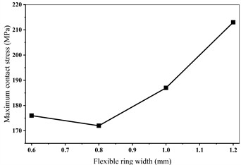
Furthermore, as plotted in the 2D line graph (Fig. 8), the maximum contact stress (176, 172, 187, and 213 MPa) exhibits a nonlinear trend of initially decreasing and then increasing as the flexible ring width expands from 0.6 mm to 1.2 mm.
Fig. 8Effect of flexible ring width on the maximum contact stress
4. Conclusions
Based on multibody dynamics theory, a transient contact simulation model of a power rolling ring was constructed using simulation software to systematically investigate the influence mechanism of the flexible ring's width on its rolling motion trajectory and internal bending stress distribution characteristics. The simulation results indicate that, driven by the rolling friction of the inner and outer conductive rings, flexible rings of varying widths can all maintain stable motion trajectories, which verifies the kinematic rationality of the power rolling ring system's structural design during the transient contact process. During transmission, the maximum stress of the flexible ring is consistently concentrated in its dynamic contact regions with the inner and outer conductive rings. Furthermore, as the flexible ring width increases from 0.6 mm to 1.2 mm, its maximum bending stress exhibits a distinct nonlinear trend of initially decreasing and subsequently increasing. Specifically, when the flexible ring widths are 0.6 mm, 0.8 mm, 1.0 mm, and 1.2 mm, the corresponding maximum contact stresses are 176 MPa, 172 MPa, 187 MPa, and 213 MPa, respectively. Consequently, the 0.8 mm wide flexible ring demonstrates the optimal stress mitigation effect, making it the optimum dimension within the investigated parameter range. In summary, the macroscopic width parameter of the flexible ring exhibits high sensitivity and a significant regulatory effect on its microscopic contact stress levels; in practical engineering design, blindly increasing or decreasing the width will exacerbate stress concentration. The findings of this study provide a robust numerical basis for the dimensional optimization of the flexible components in power rolling rings, the extension of contact fatigue life, and the enhancement of overall transmission stability. It is recommended that further optimization of the flexible ring width be conducted in subsequent designs to achieve more balanced and superior mechanical performance.
References
-
L. Xing, J. Lu, Y. Li, and F. Ge, “Development of precision conductive slip rings for space applications,” (in Chinese), Navigation and Control, Vol. 14, No. 1, pp. 59–64, 2015, https://doi.org/10.3969/j.issn.1674-5558.2015.01.011
-
Q. Zhang, K. Zhang, J. Liu, Q. Qu, J. Jiang, and R. Li, “Review on research and development of space conductive slip ring technology,” (in Chinese), Journal of Mechanical Engineering, Vol. 58, No. 22, pp. 334–348, 2022, https://doi.org/10.3901/jme.2022.22.334
-
Y. Chen et al., “Study on electrical contact behavior and multiphysics coupling effects of space conductive slip rings considering abrasive particles,” (in Chinese), Equipment Environmental Engineering, Vol. 22, No. 9, pp. 126–137, 2025.
-
L. Sun, X. Wang, and L. Wang, “Optimization design of rolling rings,” (in Chinese), Journal of Dalian Railway Institute, No. 3, pp. 56–60, 1999.
-
Z. Liu, X. Hou, L. Wang, X. Qin, and C. Song, “Thermal analysis of a novel space high-power rolling ring,” (in Chinese), Spacecraft Engineering, Vol. 26, No. 4, pp. 52–59, 2017, https://doi.org/10.3969/j.issn.1673-8748.2017.04.009
-
Z. Li, Z. Qian, Z. Wang, and W. Zhao, “Research on the technology of space high-power long-life rolling ring electrical transmission device,” (in Chinese), Manned Spaceflight, Vol. 21, No. 5, pp. 498–502, 2015, https://doi.org/10.16329/j.cnki.zrht.2015.05.012
-
J. Deng, L. Zhang, H. Wu, and P. Zhou, “Research on rolling electrical rotary transmission technology,” (in Chinese), Machinery Design and Manufacture, No. 2, pp. 37–39, Feb. 2017, https://doi.org/10.19356/j.cnki.1001-3997.2017.02.010
-
T. Chen, C. Song, H. Wu, L. Zhang, B. Lyu, and Y. Zhang, “Friction performance and damage analysis of rolling current-carrying elastic rings under different rotational speeds,” (in Chinese), Lubrication Engineering, Vol. 48, No. 12, pp. 1–7, Dec. 2023, https://doi.org/10.3969/j.issn.0254-0150.2023.12.001
-
K. Yang, B. Zhang, H. Gao, X. Cui, and H. Zhang, “Simulation and experimental research on the failure mechanism of thin-walled gear rings,” Reviews on Advanced Materials Science, Vol. 65, No. 1, p. 20250196, Jan. 2026, https://doi.org/10.1515/rams-2025-0196
-
Q. Wang, T. Li, J. Tang, and Z. Sun, “Dynamic analysis of thin-web helical gears systems based on various types of discretized-analytical modelling methods,” Machines, Vol. 14, No. 5, p. 482, Apr. 2026, https://doi.org/10.3390/machines14050482
-
S. Li, “Diaphragm stress analysis and fatigue strength evaluation of the flex-spline, a very thin-walled spur gear used in the strain wave gearing,” Mechanism and Machine Theory, Vol. 104, pp. 1–16, Jun. 2016, https://doi.org/10.1016/j.mechmachtheory.2016.05.020
-
F. Sadeghi, B. Jalalahmadi, T. S. Slack, N. Raje, and N. K. Arakere, “A review of rolling contact fatigue,” Journal of Tribology, Vol. 131, No. 4, p. 041403, Oct. 2009, https://doi.org/10.1115/1.3209132
-
J. Li et al., “Analysis of the influence of flexible ring fillet length on the contact characteristics and motion stability of power roll rings,” Mechatronic Systems and Materials Proceedings, Vol. 1, pp. 7–11, Jan. 2026, https://doi.org/10.21595/msmp.2025.25445
-
S. Baragetti, “Finite element analysis and experiments for predicting fatigue and rolling contact fatigue behavior of spur gears,” Periodica Polytechnica Mechanical Engineering, Vol. 66, No. 4, pp. 304–313, Jan. 2022, https://doi.org/10.3311/ppme.18423
-
E. Brassitos and N. Jalili, “Design and development of a compact high-torque robotic actuator for space mechanisms,” Journal of Mechanisms and Robotics, Vol. 9, No. 6, p. 061002, Dec. 2017, https://doi.org/10.1115/1.4037567
About this article

The authors would like to thank the Science and technology development plan project of Jilin province No. YDZJ202401326ZYTS and the Gan-Po Talent Support Program of Jiangxi Province No. 20243BCE51035.
The datasets generated during and/or analyzed during the current study are available from the corresponding author on reasonable request.
The authors declare that they have no conflict of interest.

