Abstract
The power slip ring is a core component for rotating electrical transmission in aerospace applications. Bending stress concentration in the flexible ring remains a critical bottleneck limiting service life, and quantitative characterization of stress sensitivity under multi-parameter coupling is lacking. Taking the maximum bending stress as the evaluation metric, an orthogonal numerical simulation was conducted. Three factors – the number of flexible rings/idler wheels, idler wheel radius, and rotational speed of the inner conductive ring – were selected, each with four levels. Range and variance analyses quantified the influence patterns. Results demonstrate that the idler wheel radius exerts a highly significant effect (P-value extremely small), while the number of flexible rings/idler wheels and rotational speed have relatively minor impacts. The idler wheel radius is identified as the primary control parameter for stress reduction, providing a quantitative basis for structural optimization and service life extension.
1. Introduction
Conductive slip rings are key components for transmitting current and signals between rotating mechanisms, widely used in aerospace, wind power, radar, and other fields [1]. Among them, power slip rings enable stable, low-loss transmission of high-power electrical energy, offering superior lifespan and reliability compared to conventional slip rings.
Regarding mechanism research, Zhou Wentao et al. confirmed through mechanical contact and thermo-electrical coupling simulations that electrical contact wear life is significantly lower than mechanical wear life [2]. Chen, Yang et al. demonstrated via experiments that air environments and high-current loads induce material transfer and coating damage, while gold plating on flexible rings effectively suppresses electrical noise [3]. In engineering applications, Li Zhao et al. developed a high-power, long-life slip ring, increasing single-ring transmission capacity by approximately fivefold and reducing loop resistance to 15 % of that in traditional slip rings [4]. Liu Chengshan et al. further verified through simulation and testing that flexible ring bending stress is a critical constraint for long-life design under 3 kW and 1.5×10⁵ revolution operating conditions [5]. Additionally, Yang Jinchuan et al. established a quantitative model correlating ring deformation with contact resistance [6]; Zhang et al. proposed a storage life modeling method based on contact resistance failure data [7]. Multiple studies collectively indicate that stress concentration in flexible rings is the core cause limiting long-life service [8]. Song Chenfei et al. observed high-temperature preload decay in wide-temperature vacuum tests, further corroborating the decisive role of bending stress [9]. Deng Jun et al. validated the anti-slip characteristics and dynamic rationality of the structure through dynamic simulation [10], laying the theoretical and engineering foundation for enhancing the reliability of rotating power transmission devices. In engineering practice, Zheng Chuanrong et al. [11], based on radar slip ring development, discussed the preload-deformation relationship and parameter selection for elastic (flexible) rings, noting the lack of systematic quantitative criteria for their geometric parameter design. Although existing research has explored electrical contact wear, material matching, and dynamic characteristics – and identified flexible ring stress concentration as the core factor limiting longevity [8] – three shortcomings remain: first, a lack of quantitative characterization and prioritization of stress sensitivity under multi-parameter coupling involving flexible ring/idler wheel count, idler radius, and inner conductive ring rotational speed; second, the influence patterns of idler geometric parameters on stress have not been systematically quantified, and their applicability under multi-contact conditions requires verification; and third, there is a lack of quantitative structural optimization criteria based on orthogonal numerical simulations, making it difficult to balance lightweight design, lifespan, and assembly processes.
2. Orthogonal numerical simulation analysis
In this study, 16 orthogonal experimental models were constructed using the finite element method based on an L16(43) orthogonal array, in which L16 denotes 16 test runs and 4³ represents three influencing factors, each assigned four levels. Each level of every factor occurs exactly the same number of times across the 16 runs, ensuring an unbiased estimation of the influence of each level on the evaluation index. Furthermore, all level combinations between any two factors occur strictly once and only once throughout the 16 runs, so that the main effects of the factors are fully decoupled, allowing the contribution of each factor to the bending stress to be quantified independently. Three factors – the number of flexible rings/idler wheels, the idler wheel radius, and the rotational speed of the inner conductive ring – each at four levels, were selected for the simulation analysis, and the specific parameters are listed in Table 1.
Table 1Factors and levels for orthogonal numerical simulation
Level | Factor | ||
A | B | C | |
Number of rings/idlers (n) | Idler wheel radius (mm) | Rotational speed (r/min) | |
1 | 11 | 6.74 | 60 |
2 | 12 | 6.78 | 120 |
3 | 13 | 6.82 | 240 |
4 | 14 | 6.86 | 300 |
2.1. Analysis of maximum bending stress patterns
A finite element model of the power slip ring was established using COMSOL. The flexible ring has an outer diameter of 38.5 mm, a deformation of 0.5 mm, a width of 5 mm, and a thickness of 0.6 mm. H62 brass was used for the outer and inner conductive rings, and C17200 beryllium bronze was adopted for the flexible ring. The friction coefficient at the contact interface was set to 0.1, the penalty function method was employed (penalty factor multiplier 1×10⁻⁵), and the initial contact state was defined as “contact”.
Taking the maximum bending stress of the flexible ring as the evaluation metric, a gradient test was performed on the number of hexahedral elements in the flexible ring mesh (1800, 3600, 7200 and 14400, in sequence). The results show that the stress results tend to converge once the element count reaches 7200; therefore, this mesh density was adopted for all subsequent simulations. The complete finite element model of the power slip ring comprises 376,300 domain elements, 1,016 vertex elements and 70,616 edge elements, with a minimum element quality of 0.02029 and an average element quality of 0.6226.
On this basis, a preliminary model was established, in which a rotational speed of 45 r/min was applied to the inner conductive ring, with the calculation duration set to three times the rotation period and a time step of 0.02. Subsequently, the orthogonal experiments were conducted. The specific parameters are listed in Table 2.
Table 2Orthogonal test matrix for simulation parameters
Test No. | Number of rings/idlers (n) | Idler wheel radius (mm) | Rotational speed (r/min) | Maximum bending stress (MPa) |
1 | 11 | 6.74 | 60 | 94.6 |
2 | 11 | 6.78 | 120 | 117.85 |
3 | 11 | 6.82 | 240 | 166.1 |
4 | 11 | 6.86 | 300 | 289.35 |
5 | 12 | 6.74 | 120 | 94.2 |
6 | 12 | 6.78 | 60 | 115.95 |
7 | 12 | 6.82 | 300 | 165.7 |
8 | 12 | 6.86 | 240 | 288.45 |
9 | 13 | 6.74 | 240 | 93.8 |
10 | 13 | 6.78 | 300 | 116.05 |
11 | 13 | 6.82 | 60 | 166.3 |
12 | 13 | 6.86 | 120 | 288.55 |
13 | 14 | 6.74 | 300 | 94.4 |
14 | 14 | 6.78 | 240 | 116.15 |
15 | 14 | 6.82 | 120 | 167.9 |
16 | 14 | 6.86 | 60 | 289.65 |
This study adopts the maximum bending stress in the flexible ring as the primary evaluation metric. As summarized in Table 2, the resulting maximum bending stresses under various operating conditions are illustrated in Fig. 1.
Fig. 1Maximum bending stress of the flexible ring under various operating conditions
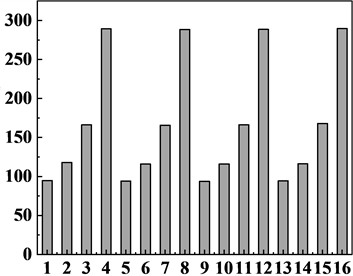
As can be seen from the figure, the four groups with the smaller idler wheel radius – namely Test No. 1, 5, 9 and 13 – all exhibit a maximum bending stress lower than those of the other three groups, with the smallest maximum bending stress of 93.8 MPa obtained under operating condition Test No. 9. Conversely, the four groups with the larger idler wheel radius – namely Test No. 4, 8, 12 and 16 – all exhibit a maximum bending stress higher than those of the other three groups, with the largest maximum bending stress of 289.65 MPa obtained under operating condition Test No. 16.
2.2. Orthogonal analysis of maximum bending stress
2.2.1. Range analysis of maximum bending stress in the flexible ring
Based on Table 2, the mean () and range (Delta) of the maximum bending stress were calculated for each factor level to construct the range analysis table. indicates the influence trend, while the range quantifies the effect significance for determining the priority of factors.
Table 3Orthogonal range analysis of maximum bending stress
Test No | K1 | K2 | K3 | K4 | Delta | Ranking of factor |
Number of rings/idlers (n) | 166.97 | 166.07 | 166.18 | 167.03 | 0.96 | 3 |
Idler wheel radius (mm) | 94.25 | 116.50 | 166.50 | 289.00 | 194.75 | 1 |
Rotational speed (r/min) | 166.63 | 167.13 | 166.12 | 166.38 | 1.01 | 2 |
Verification metric maximum bending stress (MPa) | ∑ = 2665 | |||||
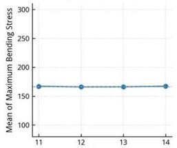
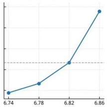
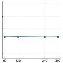
To visually demonstrate the effects of different factors and their levels on the response, the factor-response relationship plot was constructed based on the data in Table 3, as presented in Fig. 2.
Fig. 2Relationship between factors and test index
a) Flexible ring/idler count
b) Idler wheel radius
c) Inner conductive ring speed
The main-effect polylines in Fig. 2 intuitively reflect the degree of influence of each factor. The stress response to the idler wheel radius exhibits nonlinear acceleration, with the stress rising sharply from 94.25 MPa to 289.00 MPa as the radius increases (range: 194.75 MPa), indicating extremely strong geometric sensitivity. In contrast, the polylines for the number of flexible rings/idler wheels and the rotational speed of the inner conductive ring are nearly horizontal, with ranges of only 0.96 MPa and 1.01 MPa, respectively, indicating that within the intervals of 11-14 and 60-300 r/min both factors exert negligible effects and show no monotonic trend, thereby providing clear design freedom for balancing process requirements and structural performance in engineering practice.
2.2.2. Variance analysis of maximum bending stress in the flexible ring
To statistically validate the aforementioned intuitive findings and quantify the significance of each factor's influence, Analysis of Variance (ANOVA) was employed. This method decomposes the total variation into contributions from individual factors and random error, utilizing the F-test and P-values (with 0.05 indicating statistical significance) to verify the authenticity and importance of factor effects. Based on the orthogonal array data from Table 2, the resulting ANOVA table is presented as Table 4.
Based on the ANOVA results (Table 4) with a significance threshold of 0.05, the idler wheel radius exhibited an extremely small P-value, confirming its highly significant effect on the maximum bending stress. In contrast, the P-values for the number of flexible rings/idler wheels and the inner conductive ring speed were both greater than 0.05, indicating that their effects are not significant at the 0.05 level. The idler wheel radius is thus the dominant factor, while the other two are secondary factors with comparable minor contributions. It is concluded that the idler wheel radius is the primary control parameter for stress reduction, while the ring count and rotational speed can be optimized to balance assembly feasibility and dynamic performance.
Table 4Variance analysis of maximum bending stress in the flexible ring
Source | Number of flexible rings/idlers | Idler wheel radius | Rotational speed of the inner conductive ring | Error | Total |
Degrees of freedom | 3 | 3 | 3 | 6 | 15 |
Adj SS | 3.09 | 90905.18 | 2.19 | 1.38 | 90911.84 |
Adj MS | 1.03 | 30301.72 | 0.73 | 0.229 | 30303.48 |
F value | 4.49 | 132225.73 | 3.18 | ||
P value | > 0.05 | < 0.01 | > 0.05 | ||
S = 0.479, R-sq = 99.9985 %, R-sq = 99.9962 % | |||||
3. Conclusions
Addressing three core bottlenecks in existing power slip ring research – lack of quantitative characterization for stress sensitivity under multi-parameter coupling, unsystematic quantification of idler wheel geometric effects, and insufficient orthogonal numerical basis for structural optimization – this study took the maximum bending stress of the flexible ring as the core evaluation index, and adopted a hybrid approach combining orthogonal finite element simulation. The main conclusions are as follows:
1) The idler wheel radius is the decisive dominant factor, with a range of 194.75 and 0.05. The contact mechanics mechanism indicates that the radius directly determines the pre-deformation curvature of the flexible ring and the position of the contact point. When the radius increases from 6.74 mm to 6.86 mm – by only 0.12 mm – it induces a pronounced change in the bending curvature, leading to a sharp accumulation of strain energy and a drastic variation in contact stress, which produces an approximately threefold increase in stress and demonstrates extremely strong geometric sensitivity. Therefore, in the optimization design, the tolerance band of the idler wheel radius should be strictly controlled as the primary consideration.
2) The number of flexible rings/idler wheels and the rotational speed of the inner conductive ring are secondary factors, with ranges of only 0.96 and 1.01, respectively, and 0.05. The mechanical mechanism shows that an increase in the number of rings merely increases the number of rings operating in parallel; since the geometry and constraints of each individual ring remain unchanged and each ring bears the load independently, the stress is hardly affected. Meanwhile, the rotational speed within 60-300 r/min belongs to a typical low-speed operating condition, where the centrifugal force effect is minimal, so its contribution to the stress is negligible and no monotonic trend is observed. In engineering practice, the design freedom provided by these two factors can be preferentially exploited to balance the load distribution, improve wear uniformity, and satisfy the assembly requirements.
3) The stress boundary conditions were clarified: the stress is only 93.8 MPa under the optimal operating condition (Test No. 9), whereas it reaches 289.65 MPa under the worst operating condition (Test No. 16). Comparison of these extreme cases further verifies the strong positive correlation between idler radius and bending stress, providing critical data for safety margin design of power slip rings.
References
-
Z. L. Liu et al., “Key technologies of a novel roll-ring for space applications,” (in Chinese), Spacecraft Environ Eng, Vol. 33, No. 1, pp. 72–76, 2016, https://doi.org/10.12126/see.2016.01.012
-
W. T. Zhou, “Analysis of the characteristics of contact mechanics and wear life of slip ring with electrical contact,” (in Chinese), Xiangtan University, Xiangtan, China, 2014.
-
J. Chen, F. Yang, K. Luo, Y. Wu, and M. Rong, “Experimental investigation of the electrical contact characteristics in rolling contact connector,” in IEEE 61st Holm Conference on Electrical Contacts (Holm), pp. 235–240, Dec. 2015, https://doi.org/10.1109/holm.2015.7355103
-
Z. Li et al., “Research on high-power and long-life roll ring for electric transmission in space,” (in Chinese), Manned Spaceflight, Vol. 21, No. 5, pp. 498–502, 2015, https://doi.org/10.16329/j.cnki.zrht.2015.05.012
-
C. S. Liu, X. Q. Chen, and Z. Y. Qian, “Research on friction pair of space high-power and long-life rolling ring,” (in Chinese), Spacecraft Engineering, Vol. 28, No. 1, pp. 60–68, 2019, https://doi.org/10.3969/j.issn.1673-8748.2019.01.009
-
J. C. Yang et al., “Analysis of mechanical characteristics and optimum design on assembling of rolling collector ring,” (in Chinese), Chinese Journal of Engineering Design, Vol. 23, No. 4, pp. 364–370, 2016.
-
J. Zhang, X. Ma, B. Cheng, and Y. Zhao, “Storage life modeling and analysis for contacting slip ring based on physics of failure,” IEEE Transactions on Components, Packaging and Manufacturing Technology, Vol. 7, No. 12, pp. 1969–1980, Oct. 2017, https://doi.org/10.1109/tcpmt.2017.2751583
-
H. H. Wu, “Research on service stability improvement of aerospace rolling electrical transmission elastic components,” (in Chinese), Central South University, 2025, https://doi.org/10.27661/d.cnki.gzhnu.2025.000385
-
C. F. Song et al., “Effect of vacuum temperature on the tribological performance of current-carrying flexible ring rolling,” (in Chinese), Chinese Space Science and Technology, Vol. 45, No. 2, pp. 25–32, 2025, https://doi.org/10.16708/j.cnki.1000-758x.2025.0019
-
J. Deng et al., “Research on rolling rotation electrical transmission technology,” (in Chinese), Machinery Design and Manufacture, No. 2, pp. 37–39, 2017, https://doi.org/10.19356/j.cnki.1001-3997.2017.02.010
-
C. R. Zheng and K. J. Zhao, “Study on flexible ring design of roll ring,” (in Chinese), Electro-mechanical Engineering, Vol. 27, No. 3, pp. 24–27, 2011, https://doi.org/10.19659/j.issn.1008-5300.2011.03.006
About this article

The authors would like to thank the Science and technology development plan project of Jilin province No. YDZJ202401326ZYTS and the Gan-Po Talent Support Program of Jiangxi Province No. 20243BCE51035.
The datasets generated during and/or analyzed during the current study are available from the corresponding author on reasonable request.
The authors declare that they have no conflict of interest.

