Abstract
Based on the multibody dynamics simulation method, this study systematically investigates the effect of the inner conductive ring's rotational speed variations on the dynamic behavior of the power rolling ring. By establishing the overall assembly model of the power rolling ring, assigning corresponding material properties (H62 brass and C17200 beryllium bronze) to each component, and conducting transient analysis under different inner conductive ring rotational speeds (180-1000 r/min), the motion trajectory, local stress distribution, and velocity response curves of the flexible ring were obtained. The results indicate that the resultant velocity of the flexible ring increases and its motion period shortens as the rotational speed rises. When the rotational speed exceeds 500 r/min, the system exhibits distinct start-up cycles. The number of these start-up cycles increases with higher rotational speeds, and the velocity response curve displays an oscillatory trend. The findings of this study provide a theoretical basis for the structural optimization and adaptability design of power rolling rings under varying operating conditions.
1. Introduction
The power rolling ring is a novel rotary electrical transmission device that transfers power and signals via rolling contact between a flexible body and conductive tracks [1]. It outperforms traditional sliding slip rings with larger transmission currents, lower friction torque, and highly stable contact performance. However, operating in high-speed, multi-physics coupling environments makes its dynamic forces, wear, and electrical stability exceptionally complex [2].
The rotational speed of the driving inner conductive ring is a critical parameter affecting system dynamics. While theoretical contact models offer useful fundamental references [3], variations in rotational speed directly alter the flexible ring's motion trajectory, velocity response, and stress distribution, significantly impacting service life. Industrial data indicates typical operating speeds range from 250 to 1000 r/min, where higher speeds inevitably accelerate heat generation and contact wear.
Multibody dynamics provides an effective tool for analyzing these dynamic characteristics. Previous studies have utilized coupled dynamics and finite element methods to verify the zero-slip characteristics and stress distribution patterns of space rolling rings [4]-[5], and similar methods have been proven to capture complex rolling kinematics that traditional statics overlook [6].
Despite extensive research on structural optimization [7], steady-state electrical transmission, material wear, and alternative designs [8]-[9], the dynamic impact of rotational speed remains severely under-investigated. Specifically, the high-speed motion laws and velocity response mechanisms of flexible rings are still unclear [10]. Therefore, this study establishes a multibody dynamics model of the power rolling ring to conduct transient analyses at inner ring speeds of 180-1000 r/min. By systematically evaluating the motion trajectory, local stress distribution, and velocity response, this research reveals the speed-dependent dynamic mechanisms, providing a theoretical foundation for high-speed structural optimization and adaptability design.
2. Numerical simulation analysis
2.1. 3D modeling and meshing of the power rolling ring
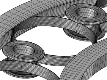
The critical component of the power rolling ring is the flexible ring. To facilitate the convergence of the simulation calculations and reduce simulation complexity, a simplified model of the power rolling ring is constructed in this study. Specifically, the model retains only the core moving and contact parts (i.e., the outer conductive ring, inner conductive ring, flexible ring, and idler structure), omitting external geometric details. Regarding the degrees of freedom, the outer conductive ring is completely fixed, while the inner conductive ring is constrained to rotate solely around its central axis to drive the flexible ring into rolling friction. These alterations strictly ensure computational efficiency without influencing the kinematic accuracy of the flexible ring's dynamic modeling. Furthermore, a fine free quadrilateral/hexahedral mesh is applied to the flexible ring, while a standard refined free quadrilateral mesh is applied to both the inner and outer conductive rings. The established mesh model of the power rolling ring is illustrated in Fig. 1. To prove that the selected grid density does not artificially influence the stress results, a mesh convergence study was conducted using the maximum bending stress as the evaluation criterion. Testing hexahedral element numbers of 1,800, 3,600, 7,200, and 14,400 demonstrated that the stress effectively converges after 7,200 elements, which was subsequently adopted. The final complete mesh of the power rolling ring comprises 376,300 domain elements, 70,616 edge elements, and 1,016 vertex elements, with an average element quality of 0.6226.
Fig. 1Mesh model of the power rolling ring
2.2. Multibody dynamics velocity contour of the power rolling ring
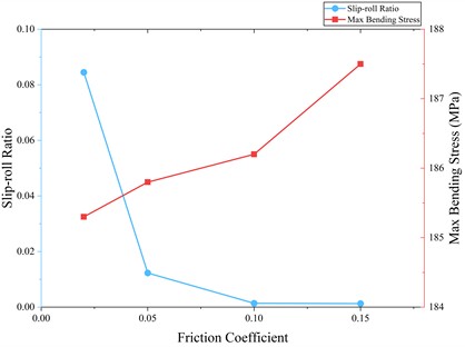
After constructing the 3D geometric model of the power rolling ring and completing the meshing, the material properties of each component were defined based on actual service conditions: H62 brass was assigned to both the inner and outer conductive rings, and C17200 beryllium bronze was used for the flexible ring, thereby establishing the complete assembly model of the power rolling ring. Regarding the boundary conditions and load settings, a preset rotational speed was applied to the inner conductive ring. Additionally, identity boundary pairs were created at the contact interfaces of the components using a penalty-formulation Coulomb friction model, with the penalty factor multiplier () set to 1e-5. To accurately reflect the actual service tribological conditions of the specific structural materials, the corresponding friction coefficients were explicitly specified as follows: 0.1 between the flexible ring and the conductive tracks, 0.08 between the flexible ring and the idler, and 0.1 between the idler and the track plates. To justify the selected baseline friction coefficient ( 0.10), a sensitivity analysis was conducted at 500 r/min (Fig. 2). The slip-roll ratio exhibits a non-linear threshold effect. Below 0.05, insufficient traction causes macroscopic slip. At 0.10, the ratio stabilizes near zero, ensuring stable pure rolling. Concurrently, the maximum bending stress increases only marginally (from 185.3 to 187.5 MPa), confirming that structural stress is dominated by radial compression rather than tangential friction. Based on these validated parameters, the subsequent transient dynamic analysis was performed.
Fig. 2Sensitivity analysis of system dynamic response to varying friction coefficients at 500 r/min
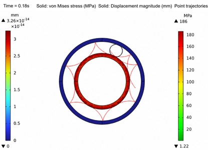
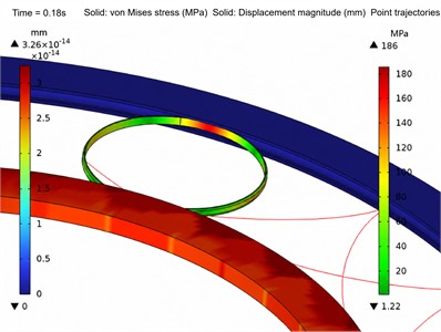
Figs. 3 to 6 illustrate the overall and local stress and displacement distribution contour plots of the power rolling ring, respectively. Specifically, the displacement distribution contour plots are extracted for the inner and outer conductive rings, whereas the equivalent stress contour plots are presented for the flexible ring. For enhanced visualization of the stress distribution and kinematic response at the critical contact interfaces, the idler structures are intentionally hidden in these post-processing contour plots. As observed from the figures, the maximum stress of the flexible ring is concentrated at its contact areas with the inner and outer conductive rings; moreover, as the rotational speed of the inner conductive ring increases, the maximum stress value at these contact points remains relatively stable without significant fluctuations.
Fig. 3Motion trajectory and local stress contour plot of the power rolling ring at 180 r/min
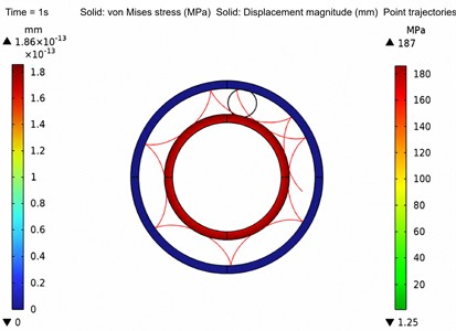
a) Motion trajectory plot
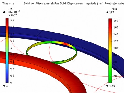
b) Local stress contour plot
Fig. 4Motion trajectory and local stress contour plot of the power rolling ring at 300 r/min
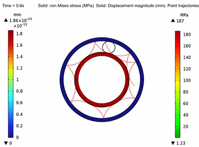
a) Motion trajectory plot
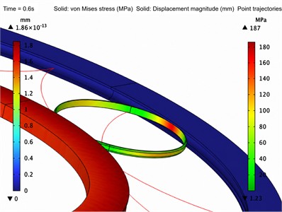
b) Local stress contour plot
Fig. 5Motion trajectory and local stress contour plot of the power rolling ring at 500 r/min
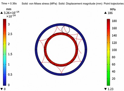
a) Motion trajectory plot
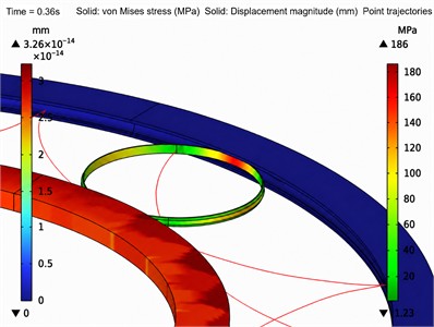
b) Local stress contour plot
Fig. 6Motion trajectory and local stress contour plot of the power rolling ring at 1000 r/min
a) Motion trajectory plot
b) Local stress contour plot
Furthermore, the red trajectory lines in the figures clearly depict the motion paths of characteristic points on the flexible ring, indicating that the dynamic response of the overall assembly structure aligns with kinematic expectations, thereby verifying the validity of the simulation. Specifically, under the speeds ranging from 180 to 1000 r/min, the maximum von Mises stress stably fluctuates around 186 to 187 MPa. Even with the uniform default visual scaling applied to all contour plots to maintain objective comparability, it is explicitly identifiable that these peak stresses are strictly localized at the extreme dynamic contact nodes between the flexible ring and the conductive tracks, confirming that no critical stress divergence occurs at high speeds.
3. Velocity variation laws of the power rolling ring
Based on the velocity analysis, the overall velocity of the flexible ring is the resultant velocity of its and components, i.e.,. Therefore, to extract this resultant velocity, two point probes are placed on the flexible ring to measure the velocity components in the and directions. Finally, the resultant velocity can be calculated by configuring a global expression in a 1D plot group.
Fig. 7Resultant velocity curve of the flexible ring at 180 r/min
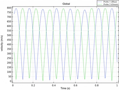
Fig. 8Resultant velocity curve of the flexible ring at 300 r/min
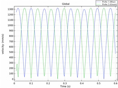
Fig. 9Resultant velocity curve of the flexible ring at 500 r/min
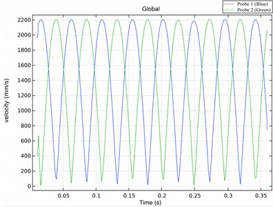
Fig. 10Resultant velocity curve of the flexible ring at 1000 r/min
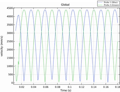
Figs. 7 to 10 display the resultant velocity curves at the two point probes of the flexible ring. The blue and green curves respectively represent the transient resultant velocities extracted from Probe 1 and Probe 2 at different spatial locations. The distinct phase difference between the two curves is attributed to their varied probe positions, while their identical oscillation frequencies confirm the uniformity of the flexible ring’s overall rolling kinematics. As observed from the figures, the velocities at both points exhibit an oscillatory trend. Moreover, with an increase in rotational speed, the resultant velocity of the flexible ring increases, and its motion period shortens. When the rotational speed of the inner conductive ring exceeds 500 r/min, start-up cycles emerge, meaning the maximum velocity does not occur in the first cycle. Furthermore, the number of start-up cycles increases as the rotational speed rises. For instance, as explicitly observed in the initial 0.15 seconds of Fig. 9 (500 r/min) and the initial 0.04 seconds of Fig. 10 (1000 r/min), the peak velocities of the initial cycles form a progressive climbing envelope before reaching stabilization. This detailed transient phenomenon perfectly illustrates the buffer process, wherein the flexible ring gradually overcomes inertia rather than undergoing an unphysical abrupt velocity jump. The obtained numerical values are reasonable, demonstrating the reliability of the results.
4. Conclusions
This study systematically investigated the dynamic impact of inner ring rotational speed on power rolling rings using multibody dynamics simulations. The results demonstrate that as the inner ring speed increases, the resultant velocity of the flexible ring rises significantly, its motion period shortens, and the velocity response exhibits distinct oscillatory characteristics. Notably, when the speed exceeds 500 r/min, the system develops significant start-up buffer cycles. During this initial phase, the flexible ring's velocity climbs progressively rather than jumping abruptly, preventing mechanical shocks and indicating excellent start-up stability under high-speed conditions. The simulation exhibits outstanding numerical reliability, providing a robust theoretical basis for the structural optimization and adaptability design of high-speed rolling rings. Future research will integrate experimental tests to further validate and refine these dynamic models.
References
-
H. Wu, H. Liu, Z. Qian, J. Liu, L. Zhang, and X. Kang, “A stable conductive structure combining multiple flexible bodies and an isolation idler,” Chinese Patent CN119182031A, 2024.
-
H. Wu et al., “Research status and progress on the current-carrying friction and wear performance of conductive slip rings in harsh environments,” Coatings, Vol. 15, No. 11, p. 1347, Nov. 2025, https://doi.org/10.3390/coatings15111347
-
T. Zhao, Z. Qi, T. Wang, and J. Xu, “Research on the calculation method of the space pulley rope contact section of nuclear ring crane based on K-T condition,” (in Chinese), Chinese Journal of Theoretical and Applied Mechanics, Vol. 56, No. 4, pp. 1123–1137, 2024, https://doi.org/10.6052/0459-1879-23-469
-
C. Liu, X. Chen, and Z. Qian, “Research on the friction pair of the space high-power and long-life rolling ring,” IOP Conference Series: Materials Science and Engineering, Vol. 638, No. 1, p. 012005, Oct. 2019, https://doi.org/10.1088/1757-899x/638/1/012005
-
Y. Sui, P. Xing, G. Li, H. Zhang, W. Wang, and H. Zhang, “Theoretical modeling and numerical simulation of current-carrying friction and wear: State of the art and challenges,” Lubricants, Vol. 13, No. 8, p. 370, Aug. 2025, https://doi.org/10.3390/lubricants13080370
-
T. Yao, L. Wang, X. Liu, and Y. Huang, “Multibody dynamics simulation of thin-walled four-point contact ball bearing with interactions of balls, ring raceways and crown-type cage,” Multibody System Dynamics, Vol. 48, No. 3, pp. 337–372, Oct. 2019, https://doi.org/10.1007/s11044-019-09704-1
-
J. Li et al., “Analysis of the influence of flexible ring fillet length on the contact characteristics and motion stability of power roll rings,” Mechatronic Systems and Materials Proceedings, Vol. 1, pp. 7–11, Jan. 2026, https://doi.org/10.21595/msmp.2025.25445
-
G. Dorsey and J. Lichter, “Alternatives to slip rings – a review,” in IEEE 70th Holm Conference on Electrical Contacts (HLM), pp. 1–8, 2025, https://doi.org/10.1109/hlm51652.2025.11278274
-
S. Yuanhang, W. Yongsong, S. Xiwu, L. Xianjun, and Y. Jianbo, “Research on failure modeling and process optimization of transmission conductive slip ring for aerospace,” (in Chinese), Journal of Mechanical Engineering, Vol. 56, No. 16, pp. 1–12, Oct. 2020, https://doi.org/10.3901/jme.2020.16.001
-
O. S. Kovtun and A. O. Polishchuk, “Electromechanical wear of the contact wire-current collecting insert pair in electric transport systems,” Problems of Tribology, Vol. 31, No. 1/119, pp. 99–105, Mar. 2026, https://doi.org/10.31891/2079-1372-2026-119-1-99-105
About this article

The authors would like to thank the Science and technology development plan project of Jilin province No. YDZJ202401326ZYTS and the Gan-Po Talent Support Program of Jiangxi Province No. 20243BCE51035.
The datasets generated during and/or analyzed during the current study are available from the corresponding author on reasonable request.
The authors declare that they have no conflict of interest.

