Abstract
The safety and stability of train traffic directly depend on the reliable operation of railroads and the condition of the subgrade. The main purpose of the research was to study the influence of vibration effects on the deformation characteristics of cohesive soils used in the subgrade of railroad embankments. The paper presents the results of compression tests, as well as deformability parameters of the studied soils under static and vibrodynamic loads. The values of deformation modulus (E) for soils of natural origin and with disturbed structure are discussed. It is confirmed that the change in the modulus of deformation of non-water saturated cohesive soils under the influence of vibration depends on changes in the stress state. The modulus of deformation of non-water-saturated clayey soils under static and vibrodynamic loads is determined by the type and nature of interactions between soil particles, as well as possible changes in the process of testing. Soil humidity is one of the key factors influencing the nature of water-colloidal bonds and deformation properties of the soil sample under both static and vibrodynamic loading conditions.
1. Introduction
The serviceability of railroad earthwork directly affects the safety and continuity of train traffic. The stress-strain state of soil structures depends not only on the impact of external factors, but also on the physical nature of the soils composing the massif. The main parameters used in stability calculations are the strength characteristics of soils - angle of internal friction and specific cohesion. The main parameters used in VAT calculations are deformation characteristics of soils - deformation modulus and transverse expansion coefficient (Poisson’s ratio) [1]-[3].
The purpose of the research was to determine the deformation characteristics of cohesive soils under vibration loads, to study the influence of vibration effects on the deformation characteristics of cohesive soils and on the VAT of the subgrade of railway embankments [4]-[5].
Characteristics of physical and mechanical properties of clayey soils are determined according to standard methods and the obtained data are consistent with the data of other experts. The calculation of the VAT of the embankment taking into account the dynamic properties of the soils is based on the principles and provisions of deformable solid mechanics and experimental data [6]-[14]. Determination of physical and mechanical characteristics of embankment soils is the most important component of geotechnical engineering studies affecting the safe operation of railway infrastructure [15]-[17].
In November 2024, a group of specialists from the testing laboratory “Testing of Track and Artificial Structures” carried out a survey of the railroad embankments in the area of Burunday settlement.
Soil samples of both disturbed and undisturbed structure were taken from the body of the railroad embankments in accordance with GOST 12071-2014. Physical characteristics of undisturbed structure soils determined according to GOST 30416-2020 are presented in Table 1. Tests to determine the characteristics of deformability were performed in the compression device Kpr-1 of the Hydroproject system for samples of both undisturbed and disturbed structure with moisture and density corresponding to the natural one. The tests were conducted according to the standard methodology in accordance with GOST 12248-2010.
The novelty of scientific research is the improvement of the methodology of testing clayey soils, modeling the impact of train load and intensity of train traffic. train traffic. Identification of the regularity of the relationship between the parameters of deformability parameters of cohesive soils under static and vibration loads. As well as the regularity of the stress-strain state of railroad embankments taking into account the dynamic properties of soils of the earth bed of railway embankments.
2. Materials and methods
To conduct experimental studies, the authors used a modified version of a single-plane shear instrument VSV-25 designed by Gidroproekt, the general view of which is shown in Fig. 1.
The advantage of this device over domestic analogues is a more uniform distribution of stresses over the shear area due to the symmetrical impact of vertical and horizontal forces. Increasing the wall thickness of the device cages allowed to reach the value of relative shear deformation of the specimen of the value equal to 27 % of the inner diameter of the carriage.
To create vibrodynamic loading on the soil sample, an eccentric rotary vibrator (Fig. 1(b)) with a drive from a DC motor of PJK-25/3 brand was specially designed.
Changing the location of eccentrics on the drive shaft allows changing the amplitude of the pulsating load. The device operates in the controlled deformation mode (kinematic mode) and has additional equipment for temporary fixation of absolute shear deformations of the soil sample. The shear rate can vary from 0.5 to 0.01 mm/min. Variation of shear rate is regulated by changing the current of the power supply VSA-5K.
Fig. 1VSV-25 single plane shear instrument
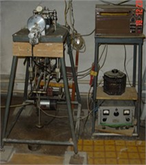
a) General view
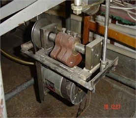
b) Eccentric rotary vibrator
The reciprocating motion of the lower movable cage of the device is created by the reduction reducer MPK-13I-5 through the spindle. The general drive of the shear force system is carried out by a DC motor D-10ARU. At vibrodynamic influence frequency of oscillations is regulated by laboratory automatic transformer “LATR”. The value of the oscillation frequency is determined by the tachometer. The tachometer is driven through the speedometer cable of the GAZ-53 car connected to the driven shaft of the rotary vibrator. The device design allows to create vibration frequency in the range from 0 to 30 Hz.
Control and measuring equipment allow to obtain quantitative values of alternating normal load N±DN both at static and vibrodynamic influences, as well as horizontal shear force and displacement of the device cage .
2.1. Test methodology
The curves plotted in Figs. 2-4 with sufficient accuracy are approximated by equations of the form:
where ; , , , , – coefficients; – relative deformation.
Fig. 2Graph of the relationship between absolute strain and tangential stress (plastic sandy loam from km 4048, PK 5, unloaded experiment)
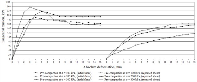
Fig. 3Graph of the relationship between absolute strain and tangential stress (plastic sandy loam from km 4048, PK 5)
Transition from shear modulus to strain modulus is made by the following dependences:
where – angular strain, – shear stress, – shear modulus, – deformation modulus, – coefficient of transverse soil expansion (Poisson’s ratio).
3. Results of the study
The results of the compression tests are presented in Table 1.
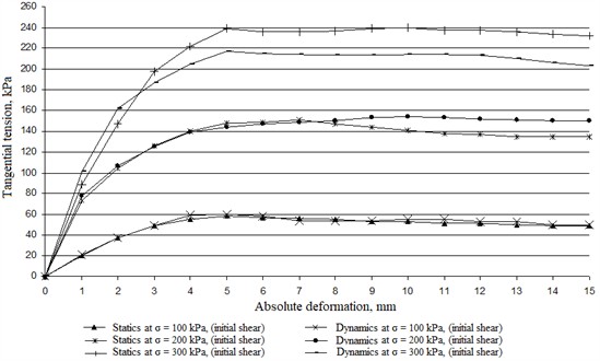
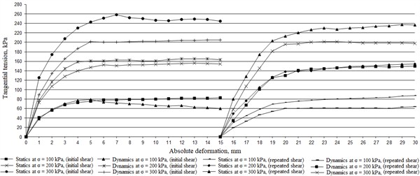
Fig. 4Graph of the relationship between absolute strain and tangential stress (Plastic sandy loam from km 4048, PK 5)
It can be seen from the table that the value of modulus of deformation for disturbed soil is slightly lower than that of the soil of natural composition.
This can be explained by the destruction of structural bonds between soil particles.
Table 3 shows the deformability parameters of the studied soils under static and vibrodynamic loading.
Table 1Physical properties of soils
Selection site | Body of the railroad embankment of Burunday settlement | ||
Km, PK | 4048 PK 5 | 4049 PK 6 | 4049 PK 4 |
Sampling depth, m | 1,5 | 12,6 | 9,0 |
Natural moisture content, , d.u. | 0,213 | 0,234 | 0,233 |
Velocity limit, , e.d.u. | 0,247 | 0,302 | 0,257 |
Rolling limit, , e.d.u. | 0,188 | 0,189 | 0,207 |
Plasticity number, , e.d.u. | 0,059 | 0,113 | 0,050 |
Yield index, , d.unit. | 0,424 | 0,398 | 0,520 |
Density, , g/cm3 | 1,57 | 1,79 | 1,68 |
Solids density, , g/cm3 | 2,70 | 2,71 | 2,70 |
Dry density, , g/cm3 | 1,29 | 1,45 | 1,36 |
Porosity, , % | 52,2 | 46,5 | 49,5 |
Porosity coefficient, | 0,91 | 0,64 | 0,98 |
Moisture content, | 0,63 | 0,99 | 0,64 |
Soil type and condition | Plastic sandy loam | Tight plastic loam | Plastic sandy loam |
4. Discussion of the results
It can be seen from Fig. 2 that the peak value of tangential stress at initial shear at 100 kPa, reaches a value of 190 kPa, at 200 kPa, reaches a value of 219 kPa, at 300 kPa, reaches the value of 239 kPa, and at the repeated peak value of tangential stress at 100 kPa, reaches the value of 119 kPa, at 200 kPa, reaches the value of 157 kPa, at 300 kPa, reaches the value of 160 kPa. It means that the tested soil (plastic sandy loam) resists better at initial (unbroken structure) shear forces than at repeated passage of the carriage (broken structure).
Fig. 3 shows that the peak value of tangential stress under static loading conditions under initial shear at 100 kPa, reaches a value of 58 kPa, at 200 kPa, reaches a value of 150 kPa, at 300 kPa, reaches the value of 218 kPa, and under dynamic repeated loading, the peak value of tangential stress at 100 kPa, reaches the value of 60 kPa, at 200 kPa, reaches the value of 152 kPa, at 300 kPa, reaches the value of 240 kPa. The difference between static and dynamic tests of the tested soil (plastic loam, unbroken structure) is not significant at 100 kPa and 200 kPa, and at 300 kPa, the value of tangential stress under dynamic influence decreases by 11 %.
Table 2Indices of soil compressibility
Km, PK, sampling location, sampling depth | Normal pressure , MPa | Soil of undisturbed structure | |||
Porosity coefficient, | Compressibility (compaction) coefficient, , MPa -1 | Relative strain, | Strain modulus, , MPa | ||
4048, PK 5, body embankment, 1,5 m, plastic sandy loam | 0 | Soil of natural composition (undisturbed structure) | |||
0,05 | 0,907 | 0,986 | 0,0016 | 1,283 | |
0,10 | 0,901 | 0,759 | 0,0048 | 1,795 | |
0,20 | 0,826 | 0,654 | 0,0440 | 2,059 | |
0,30 | 0,761 | 0,462 | 0,0780 | 2,914 | |
0,40 | 0,715 | 0,284 | 0,1020 | 3,816 | |
0 | Soil of natural composition (undisturbed structure) | ||||
0,05 | 0,958 | 1,546 | 0,0036 | 0,685 | |
0,10 | 0,933 | 1,034 | 0,0057 | 1,076 | |
0,20 | 0,878 | 0,893 | 0,0389 | 1,534 | |
0,30 | 0,797 | 0,678 | 0,0614 | 2,173 | |
0,40 | 0,615 | 0,326 | 0,0926 | 2,916 | |
4049, PK 6, body embankment, 12,6 m, tight plastic loam | 0 | Soil of natural composition (undisturbed structure) | |||
0,05 | 0,629 | 0,426 | 0,0066 | 1,486 | |
0,10 | 0,615 | 0,214 | 0,0155 | 2,941 | |
0,20 | 0,607 | 0,108 | 0,0203 | 5,618 | |
0,30 | 0,599 | 0,051 | 0,0248 | 10,417 | |
0,40 | 0,585 | 0,028 | 0,0337 | 14,873 | |
0 | Disturbed soil | ||||
0,05 | 0,648 | 0,516 | 0,0089 | 1,233 | |
0,10 | 0,624 | 0,287 | 0,0178 | 2,536 | |
0,20 | 0,612 | 0,158 | 0,0226 | 4,927 | |
0,30 | 0,603 | 0,097 | 0,0274 | 8,751 | |
0,40 | 0,594 | 0,071 | 0,0312 | 12,387 | |
4049, PK 4, body embankment body, 9,0 m, plastic sandy loam | 0 | Soil of natural composition (undisturbed structure) | |||
0,05 | 0,969 | 1,246 | 0,0376 | 0,836 | |
0,10 | 0,952 | 0,416 | 0,0492 | 2,341 | |
0,20 | 0,884 | 0,263 | 0,0653 | 3,734 | |
0,30 | 0,836 | 0,135 | 0,0731 | 7,126 | |
0,40 | 0,784 | 0,086 | 0,0843 | 9,481 | |
0 | Disturbed soil | ||||
0,05 | 1,084 | 1,437 | 0,0532 | 0,536 | |
0,10 | 1,027 | 0,684 | 0,0651 | 1,926 | |
0,20 | 0,973 | 0,495 | 0,0793 | 2,837 | |
0,30 | 0,927 | 0,318 | 0,0912 | 6,138 | |
0,40 | 0,871 | 0,237 | 0,108 | 8,874 | |
Table 3Deformation characteristics of soils
Sampling location | Type and condition of soil | , MPa | , MPa | , MPa |
Embankment body 1.5 m, km 4048 PK 5 | Plastic sandy loam | 18,46 | 16,78 | 0,1 |
22,34 | 19,87 | 0,2 | ||
Embankment body 12.6 m, km 4049 PK 6 | Soft plastic loam | 7,34 | 5,89 | 0,1 |
11,65 | 8,74 | 0,2 | ||
Embankment body 9.0 m, km 4049 PK 4 | Plastic loam type and condition of soil | 19,28 | 17,53 | 0,1 |
24,65 | 21,97 | 0,2 |
From Fig. 4, it can be concluded that the peak value of tangential stress under static loading and initial shear at 100 kPa, reaches a value of 80 kPa, and under dynamic reward and initial shear at 100 kPa, reaches a value of 82 kPa, under static loading and initial shear at 200 kPa, reaches a value of 162 kPa, and with dynamic reward and initial shear at 200 kPa, reaches a value of 158 kPa, with static loading and initial shear at 300 kPa, reaches a value of 258 kPa, and with dynamic reward and initial shear at 300 kPa, reaches a value of 204 kPa, under static loading and repeated shear at 100 kPa, reaches a value of 88 kPa, and under dynamic reward and initial shear at 100 kPa, reaches a value of 64 kPa, under static loading and repeated shear at 200 kPa, reaches a value of 158 kPa, and under dynamic reward and initial shear at 200 kPa, reaches a value of 156 kPa, under static loading and repeated shear at 100 kPa, reaches a value of 238 kPa, and under dynamic reward and initial shear at 100 kPa, reaches a value of 198 kPa. This indicates that the soils in the embankment subjected to large dynamic loads are most susceptible to shear. If the shear forces reach the peak value, the process becomes irreversible, which will lead the embankment body to slump.
5. Conclusions
The results of experimental studies allow us to draw the following conclusions:
1) It is confirmed that the change of deformation modulus of non-water-saturated cohesive soils under vibrodynamic actions depends on the change of stress state.
2) Modulus of deformation of non-water-saturated clayey soils under static and vibrodynamic impacts depends on the type and nature of contact interactions between soil particles and the possibility of changes in the process of testing. At the same time moisture content is one of the main factors influencing the nature of water-colloidal bonds in the soil and deformation properties of the soil sample under static and vibrodynamic loading.
3) For calculations of VAT of railway embankments, it is reasonable to take deformability parameters obtained during vibration tests on shear or triaxial apparatus as design characteristics.
References
-
M. Y. Kvashnin, “Experimental investigations of strength characteristics of clayey soils for forecasting of transport structures stability,” Ph.D. Thesis, Almaty, 2005.
-
V. A. Khomyakov, E. A. Isakhanov, and M. Y. Kvashnin, “Some peculiarities of soil testing in shear devices,” in Proceedings of the International geotechnical symposium, 2003.
-
A. M. Karaulov, K. V. Korolev, L. A. Bartolomey, and E. P. Bragar, “To the statistical analysis of soil shear tests results,” (in Russian), Construction and Geotechnics, Vol. 11, No. 3, pp. 8–17, Dec. 2020, https://doi.org/10.15593/2224-9826/2020.3.01
-
M. Y. Kvashnin, B. A. Abiev, and I. S. Bondar, “Influence of loading conditions on soil shear resistance,” Bulletin of KazATK, Vol. 56, No. 1, pp. 5–12, 2009.
-
I. S. Bondar, “Shear tests of cohesive soils under different loading trajectories,” Engineering and Construction Journal, Vol. 7, No. 7, pp. 50–57, 2012.
-
E. S. Ashpiz, “Instruction for vibration diagnostics of high embankments on railroads of JSC Russian Railways,” JSC Russian Railways, Moscow, No. 2561r, Oct. 2014.
-
E. S. Ashpiz, “Instruction for vibration diagnostics of embankments on weak foundations,” JSC Russian Railways, Moscow, No 2541r, Dec. 2012.
-
L. S. Blazhko, S. N. Chuyan, V. B. Zakharov, and E. V. Chernyaev, “Analysis of ways to improve the bearing capacity of soils of the main section of the earth bed,” Izvestiya PSUPSa, Vol. 13, No. 3(48), pp. 328–336, 2016.
-
M. Y. Kvashnin, S. A. Kosenko, N. M. Kvashnin, and I. S. Bondar, “Experimental studies of the vibrodynamic impact of the mobile load on the main site of the subgrade in cold regions,” in 2nd International Symposium on the Problems of the Subgrade in Cold Regions, 2015.
-
M. Y. Kvashnin, I. S. Bondar, A. B. Zhumaseitova, and G. S. Bikhozhаeva, “To the issue of vibrodynamic impact of mobile load on the main site of the earth bed,” Bulletin of KazATK, Vol. 96, No. 1, pp. 7–12, 2016.
-
A. L. Lanis and D. A. Razuvaev, “Strengthening of the earth bed soils on the approaches to the bridges and overpasses,” Vestnik of Rostov State University of Railway Engineering, Vol. 63, No. 3, pp. 97–104, 2016.
-
A. V. Zamukhovsky, S. A. Burombaev, M. Y. Kvashnin, I. S. Bondar, and A. P. Shmakov, “Vibrations of the earth bed soil on the approaches to the bridges,” in 15th International Scientific and Technical Conference Modern problems of design, construction and operation of railway track. Readings in memory of Professor G.M. Shakhunyants, 2017.
-
M. Y. Kvashnin, S. A. Kosenko, and I. S. Bondar, “Vibrodiagnostics of the approach embankment of the railway bridge,” Vestnik of SGUPS, Vol. 41, No. 2, pp. 34–39, 2017.
-
I. S. Bondar, G. B. Karibaeva, and A. K. Kurbenova, “Vibration diagnostics of transportation structures on railroads,” Vibroengineering Procedia, Vol. 54, pp. 109–115, Apr. 2024, https://doi.org/10.21595/vp.2024.24093
-
A. Akbayeva et al., “Development of safety methods on artificial structures of railway lines,” Eastern-European Journal of Enterprise Technologies, Vol. 6, No. 1(120), pp. 43–52, Dec. 2022, https://doi.org/10.15587/1729-4061.2022.269964
-
I. S. Bondar, D. T. Aldekeyeva, and Z. K. Ospanova, “Stress-strain states of reinforced concrete spans of a railroad overpass using a spatial finite element model,” Vibroengineering Procedia, Vol. 54, pp. 320–326, Apr. 2024, https://doi.org/10.21595/vp.2024.24086
-
A. N. Bogomolov et al., “Risk assessment of landslide process occurrence and assignment of reserve coefficients when calculating slopes of soil structures for stability,” in Engineering Problems of Building Materials Science, Geotechnical and Road Construction, 2012.
About this article

The authors have not disclosed any funding.
The authors would like to express their gratitude to NC KTZh JSC, Almaty distance railway department (ТP-46) for the opportunity and assistance in organizing the field studies.
The datasets generated during and/or analyzed during the current study are available from the corresponding author on reasonable request.
The authors declare that they have no conflict of interest.
