Abstract
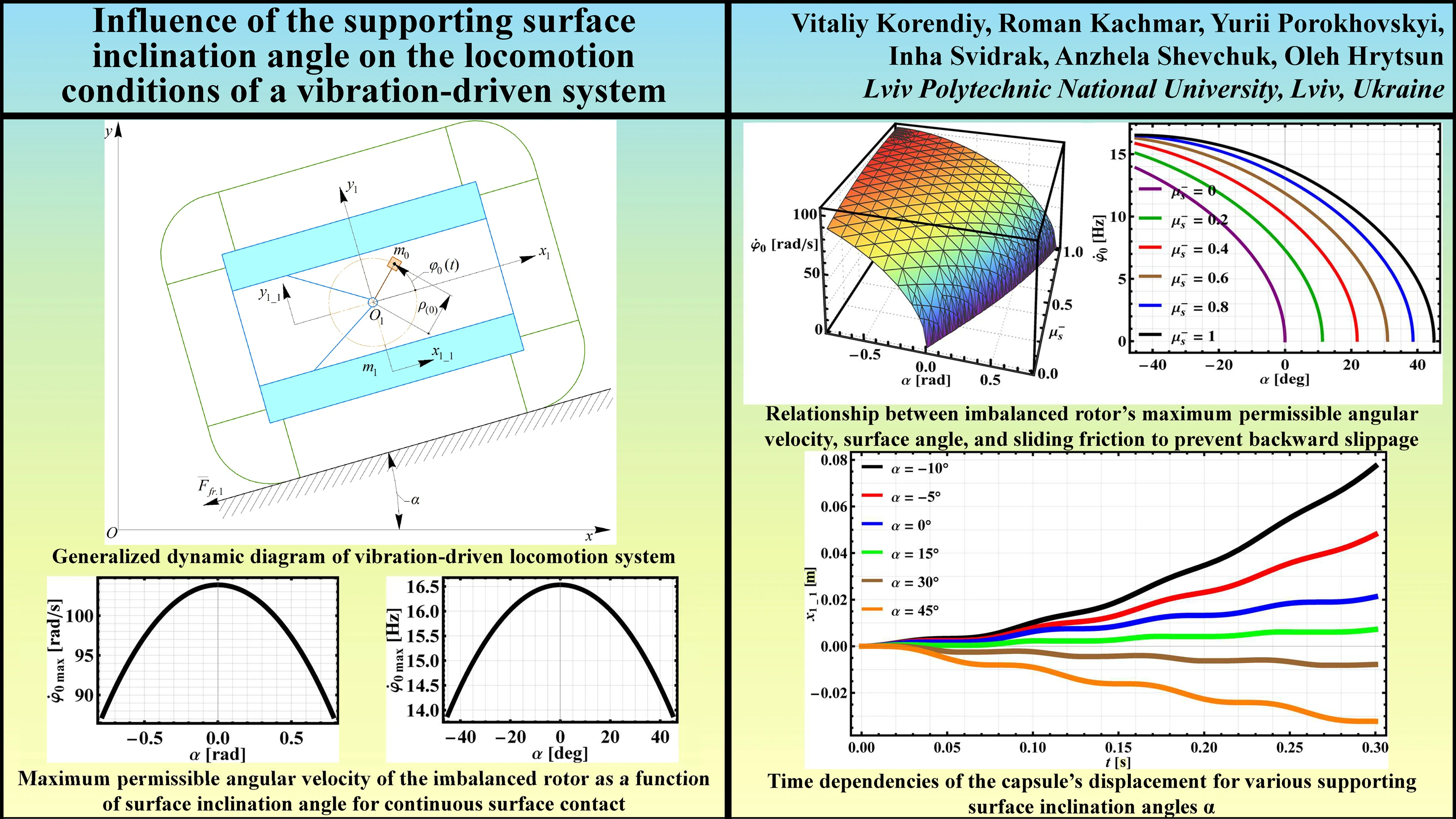
This paper investigates the influence of supporting surface inclination angle on the locomotion of a capsule-type robot driven by an imbalanced rotor, considering dry anisotropic friction. Using Lagrange’s second-order differential equations, a mathematical model is developed, and numerical simulations are performed with Wolfram Mathematica software. The scientific novelty lies in the comprehensive analysis of how inclination angle, coupled with anisotropic friction, affects the capsule’s motion, including the derivation of analytical conditions for maintaining a “non-detachable” motion regime and preventing backward slippage. Key results include the establishment of relationships for the maximum permissible angular velocity of the imbalanced rotor as a function of surface inclination angle and friction coefficient. It is found that this velocity is maximal on horizontal surfaces and decreases with increasing inclination, while higher backward friction coefficients allow for greater rotor speeds. The practical value of these findings is significant for the design and control of vibration-driven robots, particularly for applications such as pipeline inspection, monitoring, and cleaning, where reliable navigation across varied inclinations is crucial.
Highlights
- Analytical conditions providing non-detachable motion and preventing backward slip of vibration-driven capsules on inclines are derived considering dry anisotropic friction.
- Maximal permissible rotor speed for stable, non-detachable motion is highest on horizontal surfaces and decreases significantly with increasing inclination.
- Higher backward static friction enables greater rotor speeds to prevent slip; however, increasing surface inclination consistently lowers this permissible speed.
- A critical uphill inclination was identified, beyond which forward capsule motion ceased under the studied parameters, with steeper angles causing backward sliding.
- Average forward velocity on inclines decreases with angle, approximated by a 5th-order polynomial, aiding design for pipeline inspection robots.
1. Introduction
Vibration-driven systems have garnered significant attention in recent years due to their potential applications in various fields, including robotics, automation, and biomedical engineering. For example, in [1], the authors explored vibration drives with two impacting pairs for precise robots, focusing on the design and analysis of such mechanisms. Following this, Ragulskis et al. [2] investigated the dynamics of a pipe robot with a vibration drive based on centrifugal forces, contributing to the understanding of locomotion in confined environments. Further work [3] examined the dynamics of a manipulator with a self-stopping mechanism and a vibration drive also based on centrifugal forces, highlighting the versatility of vibration-based actuation. The locomotion of these systems is affected by various factors, including system, environmental, and operational parameters. Zarychta et al. optimized control for capsule drives using neural networks [4] and Fourier series [5], highlighting the importance of sophisticated control for enhancing locomotion efficiency and reducing power consumption.
The inclination angle of the supporting surface is a critical environmental factor for mobile vibration-driven systems operating in real-world scenarios like inclined pipelines or the gastrointestinal tract. This angle introduces gravitational forces that significantly alter locomotion. Korendiy et al. [6] modeled a three-mass vibratory system, and [7] analyzed a vibro-impact plate compactor, providing foundational understanding. Studies on wheeled robots [8, 9] showed the impact of design parameters like impact gap, while Nguyen et al. [10] emphasized the role of anisotropic friction. Duong et al. [11] and Ngo et al. [12] specifically examined the dynamic response of capsule systems on inclined surfaces, directly addressing the influence of inclination. Fang et al. [13] studied the dynamics of systems with dry friction, a factor influenced by inclination. Further research on wheeled robots focused on suspension designs [14, 15], and theoretical modeling efforts [16] provided analytical tools. Control strategies for capsule systems were explored by Zhang et al. [17], and multi-objective optimization considering the intestinal environment was performed by Jiapeng et al. [18]. Sun et al. [19] analyzed vibro-impact systems under various excitations, and Korendiy et al. [20] modeled capsule dynamics with anisotropic friction, relevant to inclined motion, which haven’t been previously taken into account.
Building on this knowledge, this paper aims to systematically investigate the influence of the supporting surface inclination angle on the locomotion conditions of vibration-driven systems. Despite existing studies touching on inclined surfaces, a comprehensive analysis of its effect on key locomotion parameters across similar systems with imbalanced rotors is still needed. This study will analyze the fundamental principles governing motion under gravity due to inclination to understand its impact on locomotion characteristics and, particularly, average velocity, contributing to the improved design and application of these systems in diverse environments.
2. Research methodology
2.1. Dynamic diagram and mathematical model of the vibration-driven system
To model the movement of a mechanical system that includes a rigid body with an attached imbalanced rotor, influenced by dry anisotropic sliding friction and without other external factors, let us refer to its simplified dynamic diagram presented in Fig. 1. Under the influence of a single external force of dry friction , which acts opposite to the motion direction, the capsule-type robot can slide along a rough supporting surface inclined at an angle to the horizon and parallel to the axis of the inertial coordinate system . The inertial coordinate systems and are referenced to the fixed surface on which the robot slides and the mass center of the capsule (the joint , at which the imbalanced rotor is installed) in the state of rest (equilibrium).
Fig. 1Generalized dynamic diagram of vibration-driven locomotion system being studied
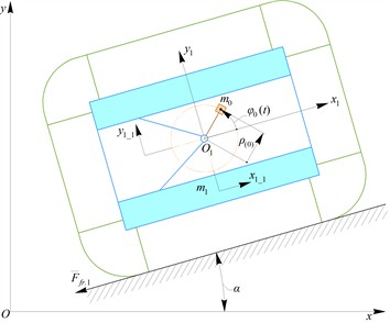
To facilitate the numerical solution of the governing differential equations and simplify the mathematical representation of the system, the following assumptions are introduced. Firstly, let us assume that the capsule is free to move upwards without any restriction from an upper support; specifically, the mass can displace along the axis under certain conditions. Secondly, the imbalanced mass is considered to be rigidly attached to the crank at a fixed radial distance from the rotational center Thirdly, let us disregard any potential changes in the angular orientation of the capsule and imbalanced mass as the robot translates in the direction. Consequently, the mechanical system under investigation is reduced to two degrees of freedom, which can be fully described by two generalized coordinates: and . These coordinates represent the displacements along the mutually perpendicular axes and of the center of mass of the rigid body with a mass as functions of time.
The locomotion behavior of the capsule-type mechanical system, featuring an imbalanced rotating mass in its plane of motion and subjected to the dry anisotropic sliding friction, is represented by a comprehensive mathematical model developed by employing the Lagrange’s second-order differential equations:
where to represent how the dry anisotropic friction coefficient changes with the change in the capsule’s movement direction, the subsequent expression is utilized:
where and signify the static friction coefficients encountered when the capsule tends to slide in the positive and negative directions of the axis, respectively; and represent the kinetic friction coefficients that arise when the capsule is in motion along and opposite to the axis direction; denotes the resultant of all inertial forces acting on the imbalanced mass , projected onto the axis, combined with the projections of the gravitational forces acting on both the capsule and the imbalanced mass onto the same axis:
In order to calculate the normal reaction force , let us employ the following expression:
where denotes the sum of projections of all inertial and gravitational forces acting upon the moving bodies onto the axis:
To find the solutions for the system of differential Eq. (1) and (2), a diverse set of numerical techniques available in the Wolfram Mathematica software will be employed. In particular, let us leverage the “StiffnessSwitching” functionality. This feature possesses the capability to automatically identify the stiffness characteristics of the system and dynamically select the most appropriate one from a variety of numerical solvers, including Runge-Kutta, Adams, Galerkin, Rosenbrock, BDF, and others. This adaptive approach aims to achieve the highest possible solution accuracy while minimizing the required computational effort.
2.2. Substantiating the locomotion modes of the vibration-driven system
Taking into account Eq. (2), let us write the condition for the “non-detachable” mode of the capsule locomotion, i.e., the absence of its “bouncing” above the supporting surface. This occurs when the projection onto the axis of the capsule’s acceleration is less than zero, i.e., . Thus, the detaching of the capsule from the supporting surface will not be observed as long as the normal reaction (normal compressive force) , with which the capsule presses on the supporting surface, and the supporting surface, in turn, acts on the capsule, is greater than zero:
Thus, analyzing Eq. (7), we can state the following. The condition for the “non-detachable” mode of the capsule movement is that the sum of projections onto the axis of all inertial forces that arise as a result of the uneven rotation of the imbalanced body must be less than the sum of projections onto the same axis of all gravitational forces acting on the bodies of the investigated mechanical system. Let us analyze the influence of inertial and excitation parameters on the conditions leading to the “detachable” locomotion mode. Assuming the angular velocity of the imbalanced body to be constant , i.e., omitting the transient regimes of operation of the imbalanced vibration exciter, based on Eq. (7) let us derive the dependence of the maximum permissible angular velocity of the imbalanced body (at ) on the inclination angle of the supporting surface in order to provide the “non-detachable” mode of the capsule locomotion:
To prevent backward slippage of the capsule under anisotropic friction, which is essential for optimal kinematic performance, the conditions initiating movement opposite to the axis must be analyzed. Based on Eq. (1), the capsule will not slip backward during a “non-detachable” motion regime if its acceleration along the axis is non-negative (i.e., ). In other words, reverse motion along the axis is avoided as long as the sum of forces promoting backward movement is less than the maximum static friction force in that direction. These promoting forces include the projections of all inertial forces from the imbalanced mass and the gravitational forces on the entire capsule (including the rotor), directed opposite to the axis. The restraining static friction force, during the “non-detachable” regime, is calculated as the product of the normal reaction force () from the supporting surface and the static sliding friction coefficient in the backward direction ():
Assuming the imbalanced rotor maintains a constant angular velocity (), which implies its angular acceleration is zero () and its angular position is , let us use Eq. (9) to determine the relationship for the maximum permissible angular velocity of the rotor (). This relationship will depend on the supporting surface’s inclination angle () and the static sliding friction coefficient in the backward direction (). The aim is to define this maximum angular velocity to prevent any backward slipping of the capsule while it operates in its “non-detachable” locomotion mode:
3. Results and discussion
3.1. Influence of the supporting surface inclination angle on the maximal permissible angular velocity of the unbalanced rotor
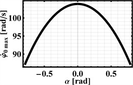
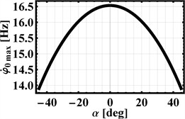
The corresponding input data for further modeling are summarized in Table 1. To develop the relevant relationship using Eq. (8), let us adjust the inclination angle of the supporting surface across a range from –45 to 45 degrees (i.e., ). The resulting dependencies are depicted in Fig. 2, which shows how the maximum permissible angular velocity (in rad/s) and the corresponding rotation frequency of the imbalanced rotor (in Hz) change with the supporting surface’s inclination angle (presented in both radians and degrees) while ensuring the capsule maintains a “non-detachable” locomotion regime.
Table 1Input parameters for modeling the influence of the supporting surface inclination angle on the capsule’s locomotion characteristics
, kg | , kg | , m | , deg | , s-1 | ||
0.1 | 1 | 0.01 | (–45; –10; –5; 0; 15; 30, 45) | 87.965 (14 Hz) | 0 | 1 |
The highest achievable values for angular velocity and rotation frequency, which reach up to 103.9 rad/s (equivalent to 16.5 Hz), occur when the capsule moves on a horizontal surface (). Consequently, as the supporting surface’s angle of inclination relative to the horizontal plane increases, the maximum allowable angular velocity of the imbalanced rotor must decrease to maintain the “non-detachable” motion of the capsule. This velocity (frequency) approaches 87.4 rad/s (13.9 Hz) as the inclination angle nears either 45° or –45°.
Fig. 2Maximum permissible angular velocity of the imbalanced rotor as a function of surface inclination angle for continuous surface contact
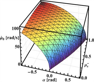
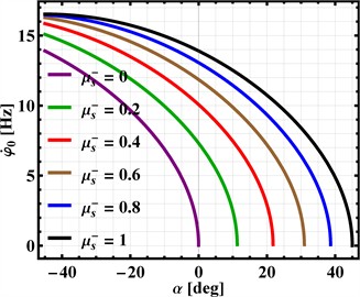
Let us now construct a graphical representation derived from Eq. (10) to illustrate how the maximum allowable angular velocity for the imbalanced rotor () is influenced by the supporting surface’s inclination angle () and the static sliding friction coefficient (). The goal is to ensure the capsule does not slip backward when operating in its “non-detachable” motion mode. This dependency is depicted in Fig. 3 through a 3D plot of the function , with measured in radians and in rad/s. For clearer interpretation of these results, Fig. 3 also incorporates a 2D plot showing the maximum rotation frequency ( in Hz) as a function of the angle ( in degrees) for various values.
Analysis of the simulation results indicates several key trends. Firstly, for a capsule on a horizontal supporting surface (), the lowest permissible angular velocities of the imbalanced rotor that prevent backward motion () occur when the friction coefficient is zero (represented by the purple curve in Fig. 3). Secondly, an increase in the static sliding friction coefficient () allows for higher permissible angular velocities () of the rotor over a wide range of surface inclination angles, specifically from −45° to 45°. Finally, for any given static sliding friction coefficient (), increasing the inclination angle () of the supporting surface necessitates a decrease in the permissible angular velocity () of the imbalanced rotor.
Fig. 3Relationship between imbalanced rotor’s maximum permissible angular velocity, surface angle, and static friction to prevent backward slippage in non-detachable motion
3.2. Example of numerical modeling of the vibration-driven system locomotion
This section of the research involves establishing the influence of the supporting surface inclination angle with respect to the horizontal on the kinematic characteristics of the capsule-type robot. The time dependencies of the capsule’s displacement and velocity during its motion along the supporting surface ( axis) for various inclination angles are presented in Figs. 4 and 5, while the dependence of the average capsule velocity on the angle is shown in Fig. 6.
It is evident that as the angle decreases, an increase in the distance the capsule can cover within a specific time will be observed (see Fig. 4). For instance, during movement downhill (at –10°), under an idealized scenario where and , the capsule traverses a distance of 0.077 m in 0.3 s. Conversely, an angle of 15° is practically the critical uphill angle that the capsule can overcome under the given conditions. That is, increasing the inclination angle of the supporting surface relative to the horizontal beyond 15° virtually prevents the capsule from moving in the positive direction of the axis. For all other angles used during the modeling, specifically 30° and 45°, the capsule is observed to slide in the opposite direction to the direction of the axis.
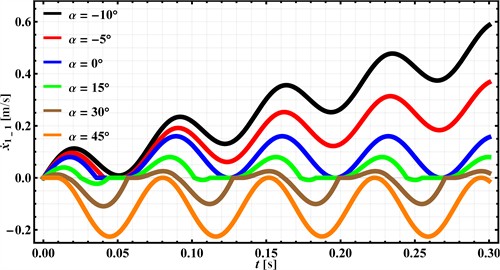
Similar conclusions can be drawn by analyzing the time dependence of the capsule’s velocity along the supporting surface, which is presented in Fig. 5. At uphill angles of 30° and 45°, the capsule’s velocity practically does not rise above zero, which indicates movement in the direction opposite to the axis. In contrast, at an angle of 15°, the capsule’s velocity practically does not decrease below zero, meaning it moves in the forward direction (along the axis). Furthermore, at angles of 0…45°, the capsule’s velocity changes according to a periodic law, and its amplitude (peak) values remain practically unchanged, whereas when the inclination angle of the supporting surface decreases to 0, i.e., during the capsule’s downhill movement, an increase in the maximum (peak) velocity value is observed. This is attributed to the influence of the gravitational force on the capsule and the absence of friction in the forward direction of motion .
Fig. 4Time dependencies of the capsule’s displacement for various supporting surface inclination angles α
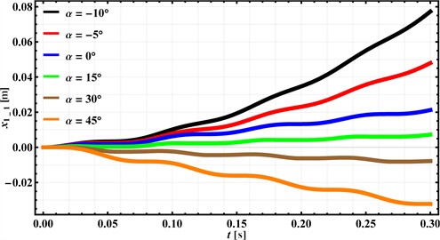
Fig. 5Time dependencies of the capsule’s velocity for various supporting surface inclination angles α
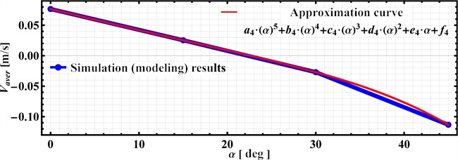
Taking into account the simulation results presented in Figs. 4 and 5, the dependence (see Fig. 6) of the average velocity of the capsule in the positive range of supporting surface inclination angles relative to the horizontal, i.e., in the range of 0°…45°, was constructed under otherwise constant conditions (see Table 1). Negative values of angles 0 were not considered, as the average velocity of the capsule during downhill movement along the inclined supporting surface constantly increases due to the influence of gravitational forces and the absence of friction forces in the direction of motion . The simulation results (blue curve with corresponding points reflecting the average velocities at 0°, 15°, 30°, 45°) were approximately fitted by a fifth-order polynomial function (the corresponding curve in Fig. 6 is shown in red):
where the approximation coefficients –2.93455∙10-10, –2.75606∙10-9, 2.79174·10-7, 4.15673∙10-6, –3.51728∙10-3, 0.0765929 are calculated with the help of the smallest squares method implemented in the Wolfram Mathematica software by the “FindFit” function.
The simulation results presented in Fig. 6 suggest that as the inclination angle of the supporting surface decreases from 45° to 0°, under otherwise constant conditions (see Table 1), the average velocity of the capsule’s movement in the direction of the axis increases from –0.113 m/s (indicating movement in the opposite direction) to a maximum value of 0.077 m/s, following an increasing power law dependence. Similar dependencies can be obtained for other fixed values of the supporting surface inclination angle under various operating conditions.
Fig. 6Time dependencies of the capsule’s velocity for various supporting surface inclination angles α
3.3. Possible applications of the carried-out investigations and obtained results
The insights gained from the comprehensive analysis of the vibration-driven capsule’s locomotion, particularly concerning the influence of supporting surface inclination and anisotropic friction, offer significant prospects for practical implementation in the field of in-pipe robotics. The detailed understanding of how parameters such as inclination angle of the pipeline, sliding friction coefficients, and imbalanced rotor angular velocity affect the “non-detachable” motion regime and the conditions for preventing backward slippage is directly applicable to the design and operational control of robots intended for pipeline inspection, monitoring, and cleaning.
Pipelines often feature varying inclinations, bends, and potentially irregular internal surfaces due to corrosion or deposits. The findings regarding the critical uphill angle (approximately 15° under the tested conditions, beyond which forward motion is hindered) and the influence of inclination on average velocity are crucial for designing pipeline inspection robots capable of navigating such complex terrains.
The derived dependencies Eqs. (8) and (10) of the maximum allowable angular velocity of the imbalanced rotor on the inclination angle and friction coefficient (as shown in Figs. 2 and 3) enable engineers to select optimal motor parameters and rotor eccentricities. This ensures reliable forward motion without backward slippage or detachment from the pipe wall, even when encountering inclines or declines. For instance, pipeline inspection robots can be designed with adaptive control systems that adjust rotor frequency based on the detected pipe inclination to maintain consistent velocity or overcome challenging sections.
The consideration of anisotropic friction and the quantification of its effects on preventing backward slippage (Eq. (10), Fig. 3) can inform the choice of materials for the robot’s contact surfaces. This can maximize traction in the desired direction while minimizing resistance, which is particularly important in pipes with varying surface conditions (e.g., smooth, corroded, coated).
The mathematical model Eqs. (1), (2) and the numerical simulation results (Figs. 4, 5, and 6) that predict displacement and velocity profiles under different inclination angles allow for more accurate mission planning and battery life management. Knowing the relationship between the angle of inclination and average velocity (approximated by a fifth-order polynomial, Eq. (11)) helps in estimating the time required for inspection runs.
Understanding the conditions for the “non-detachable” motion regime (Eq. (8), Fig. 2) is vital for ensuring that monitoring sensors remain consistently coupled to the pipe wall, preventing data loss or erroneous readings caused by robot bouncing or instability.
In summary, the carried-out investigations provide a foundational framework for developing more efficient, reliable, and versatile vibration-driven capsule robots. The quantitative understanding of how inclination angles and friction conditions influence locomotion characteristics allows for the tailored design of actuation systems, material choices, and control strategies specifically optimized for the demanding environment of pipeline inspection, monitoring, and cleaning tasks. Future developments could integrate these findings into adaptive control algorithms that allow robots to autonomously adjust their operational parameters in real-time based on sensed environmental conditions within the pipeline.
4. Conclusions
The study investigated the influence of the supporting surface inclination angle on the locomotion characteristics of a vibration-driven capsule-type system, explicitly considering dry anisotropic friction. The conditions necessary to maintain a “non-detachable” motion regime and prevent backward slippage were established by deriving analytical expressions for the maximum permissible angular velocity of the imbalanced rotor under varying inclination angles and friction coefficients. Numerical simulations demonstrated that the maximum allowable rotor speed is highest on horizontal surfaces and decreases with increasing inclination. Furthermore, while higher static friction in the backward direction permits greater rotor speeds to prevent slip, an increase in the surface inclination angle invariably reduces this permissible speed. Key kinematic parameters, including a critical uphill angle and the relationship between average velocity and inclination, were quantified for a specific example of the vibration-driven system.
These findings provide crucial insights for the design and control of such capsule robots, particularly enhancing their potential for reliable operation in applications like pipeline inspection, monitoring, and cleaning, where navigating inclined and variable-friction surfaces is essential. The results form a basis for optimizing robot parameters to ensure efficient and predictable locomotion in complex environments.
Further research could explore the influence of different excitation frequencies and eccentricities of the imbalanced rotor on the critical inclination angles and the average velocity of the capsule. Investigating the effects of varying friction coefficients and different patterns of anisotropic friction would also be valuable. Additionally, experimental validation of the simulation results would be a crucial next step to confirm the accuracy of the mathematical model and the findings of this study.
References
-
K. Ragulskis and L. Ragulskis, “Vibration drives with two impacting pairs for precise robots,” Mechanics, Vol. 29, No. 2, pp. 115–124, Apr. 2023, https://doi.org/10.5755/j02.mech.32277
-
K. Ragulskis et al., “Investigation of dynamics of the pipe robot with vibration drive based on centrifugal forces,” Agricultural Engineering, Vol. 56, No. 3, pp. 32–37, Jan. 2024, https://doi.org/10.15544/ageng.2024.56.5
-
K. Ragulskis, A. Bubulis, V. Jūrėnas, J. Vėžys, P. Paškevičius, and L. Ragulskis, “Investigation of dynamics of the manipulator with self-stopping mechanism and vibration drive based on centrifugal forces,” Mechanics, Vol. 30, No. 3, pp. 286–293, Jun. 2024, https://doi.org/10.5755/j02.mech.36275
-
S. Zarychta, M. Balcerzak, V. Denysenko, A. Stefański, A. Dąbrowski, and S. Lenci, “Optimization of the closed-loop controller of a discontinuous capsule drive using a neural network,” Meccanica, Vol. 58, No. 2-3, pp. 537–553, Feb. 2023, https://doi.org/10.1007/s11012-023-01639-4
-
S. Zarychta, M. Balcerzak, and J. Wojewoda, “Exploring iterative and non-iterative Fourier series-based methods of control optimization in application to a discontinuous capsule drive model,” Nonlinear Dynamics, Vol. 113, No. 3, pp. 2333–2353, Oct. 2024, https://doi.org/10.1007/s11071-024-10333-3
-
V. Korendiy, O. Lanets, O. Kachur, P. Dmyterko, and R. Kachmar, “Determination of inertia-stiffness parameters and motion modelling of three-mass vibratory system with crank excitation mechanism,” Vibroengineering Procedia, Vol. 36, pp. 7–12, Mar. 2021, https://doi.org/10.21595/vp.2021.21924
-
V. Korendiy et al., “Kinematic and dynamic analysis of three-mass oscillatory system of vibro-impact plate compactor with crank excitation mechanism,” Vibroengineering Procedia, Vol. 40, pp. 14–19, Feb. 2022, https://doi.org/10.21595/vp.2022.22393
-
V. Korendiy, O. Kachur, V. Gurskyi, and P. Krot, “Studying the influence of the impact gap value on the average translational speed of the wheeled vibration-driven robot,” Engineering Proceedings, Vol. 24, No. 1, p. 25, Sep. 2022, https://doi.org/10.3390/iecma2022-12897
-
V. Korendiy et al., “Motion simulation and impact gap verification of a wheeled vibration-driven robot for pipelines inspection,” Vibroengineering Procedia, Vol. 41, pp. 1–6, Apr. 2022, https://doi.org/10.21595/vp.2022.22521
-
V.-D. Nguyen, K.-T. Ho, N.-T. La, Q.-H. Ngo, and K.-T. Nguyen, “An experimental study on the self-propelled locomotion system with anisotropic friction,” in Lecture Notes in Mechanical Engineering, Singapore: Springer Singapore, 2021, pp. 537–545, https://doi.org/10.1007/978-981-16-3239-6_40
-
T.-H. Duong et al., “Dynamic response of vibro-impact capsule moving on the inclined track and stochastic slope,” Meccanica, Vol. 58, No. 2-3, pp. 421–439, Apr. 2022, https://doi.org/10.1007/s11012-022-01521-9
-
Q.-H. Ngo et al., “A vibro-impact remote-controlled capsule in millimeter scale: design, modeling, experimental validation and dynamic response,” Journal of Sound and Vibration, Vol. 596, p. 118746, Feb. 2025, https://doi.org/10.1016/j.jsv.2024.118746
-
H. Fang, Y. Zhao, and J. Xu, “Steady-state dynamics and discontinuity-induced sliding bifurcation of a multi-module piecewise-smooth vibration-driven system with dry friction,” Communications in Nonlinear Science and Numerical Simulation, Vol. 114, p. 106704, Nov. 2022, https://doi.org/10.1016/j.cnsns.2022.106704
-
V. Korendiy and O. Kachur, “Locomotion characteristics of a wheeled vibration-driven robot with an enhanced pantograph-type suspension,” Frontiers in Robotics and AI, Vol. 10, p. 12391, Aug. 2023, https://doi.org/10.3389/frobt.2023.1239137
-
V. Korendiy, P. Krot, O. Kachur, and V. Gurskyi, “Analyzing the locomotion conditions of a wheeled vibration-driven system with a v-shaped suspension,” in Lecture Notes in Mechanical Engineering, Cham: Springer Nature Switzerland, 2024, pp. 153–163, https://doi.org/10.1007/978-3-031-63720-9_14
-
V. Korendiy, O. Kachur, V. Kyrychuk, and B. Markovych, “Mathematical modeling and computer simulation of locomotion conditions of vibration-driven robots,” Mathematical Modeling and Computing, Vol. 11, No. 4, pp. 1211–1220, Jan. 2024, https://doi.org/10.23939/mmc2024.04.1211
-
Z. Zhang, J. Páez Chávez, J. Sieber, and Y. Liu, “Numerical analysis of a multistable capsule system under the delayed feedback control with a constant delay,” International Journal of Non-Linear Mechanics, Vol. 152, p. 104390, Jun. 2023, https://doi.org/10.1016/j.ijnonlinmec.2023.104390
-
Z. Jiapeng, L. Maolin, J. P. Chávez, L. Yang, and L. Tingrui, “Multi-objective optimization of a self-propelled capsule for small bowel endoscopy considering the influence of intestinal environment,” Nonlinear Dynamics, Vol. 111, No. 18, pp. 16963–16989, Aug. 2023, https://doi.org/10.1007/s11071-023-08792-1
-
Y. Sun, J. Páez Chávez, Y. Liu, and P. Perlikowski, “Response analysis of vibro-impact systems under periodic and random excitations,” Physica D: Nonlinear Phenomena, Vol. 472, p. 134476, Feb. 2025, https://doi.org/10.1016/j.physd.2024.134476
-
V. Korendiy, R. Predko, R. Stotsko, A. Kychma, O. Hrytsun, and A. Lisnichuk, “Modeling the dynamics of a capsule-type locomotion system actuated by an imbalanced rotor under the action of dry anisotropic friction,” Mathematical Modeling and Computing, Vol. 12, No. 1, pp. 310–322, Jan. 2025, https://doi.org/10.23939/mmc2025.01.310
About this article

The authors have not disclosed any funding.
The datasets generated during and/or analyzed during the current study are available from the corresponding author on reasonable request.
The authors declare that they have no conflict of interest.
