Abstract
To address the limitations of conventional vibrating screens, such as restricted operational conditions and poor adaptability, this study proposes a new type of linear vibrating screen with an adjustable vibration direction angle. By altering the fixed positions of the bolts between the vibration motors and motor supports, the angle between the vibration direction and the screen surface can be modified to achieve vibration direction angle adjustment, thereby enabling the screen to adapt to diverse working conditions. Creo and ANSYS Workbench were employed to conduct dynamic analyses of this innovative design, revealing displacement and stress distribution maps under various vibration direction angles. The results demonstrate that the new type of vibrating screen exhibits excellent structural strength and stiffness, effectively meeting industry requirements. This study provides valuable insights into the design of linear vibrating screens.
Highlights
- A new vibrating screen with adjustable vibration direction angle was proposed.
- Model establishment and dynamic analysis were conducted on the new vibrating screen.
- Analysis results demonstrate the new vibrating screen satisfies the strength and stiffness requirements.
1. Introduction
In recent years, with the increasing demand and production of coal worldwide, there has been growing global attention to the environmental issues arising from large-scale coal utilization [1]. The policy of vigorously promoting clean energy and clean coal technology has been put forward to achieve the goals of energy conservation, emission reduction, environmental protection, and improvement of coal utilization efficiency [2].
The vibrating screen is an important screening machine, which is widely used in the coal industry and plays a crucial role in coal preparation plants [3]. The vibrating screen can clean raw coal, remove impurities to obtain clean coal, improve its quality and economic benefits. It can also stratify and screen materials to meet different production requirements, thus enhancing the utilization rate of coal [4].
The vibration direction angle is an important parameter affecting the performance of the vibrating screen. The selection of the vibration direction angle is determined by the particle size and properties of the screened materials [5]. The larger the vibration direction angle, the shorter the distance that the material is thrown each time, and the slower the movement speed of the material. In this case, the material can be fully screened, which is suitable for materials that are difficult to screen. The smaller the vibration direction angle, the longer the distance that the material is thrown each time, and the faster the material passes through the screen surface. This situation is suitable for materials that are easy to screen. Selecting different vibration direction angles according to different working conditions and material characteristics helps to achieve good screening efficiency [6].
At present, the design and use of most vibrating screens are only for single-condition working scenarios, without considering multi-condition situations. The vibration direction angle is fixed and cannot be adjusted. If the characteristics of the screened materials change, the vibrating screen needs to be redesigned and reassembled to adjust the vibration direction angle. This greatly increases the production cost and reduces the production efficiency [7].
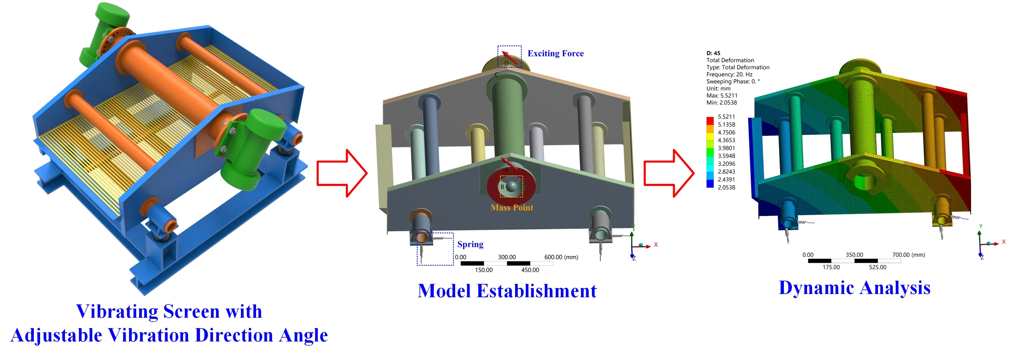
2. Model establishment
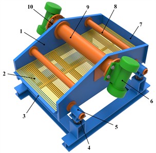
The new type of linear vibrating screen with an adjustable vibration direction angle mainly consists of a main screen body, a screen surface, a frame, rubber springs, spring supports, and vibrating motors. The main screen body is composed of side plates, reinforced tube beams, support cross - beams, a discharge port, a motor support, a rear baffle, and a main beam. The main beam, reinforced tube beams, support cross-beams, discharge port, rear baffle, motor support, and spring supports are fixed to the side plates by bolts. Two vibrating motors are respectively installed on the motor supports on both sides. The main screen body is connected to the frame through rubber springs, and the frame is fixed to the ground by foundation bolts.
Fig. 1Three-dimensional model of linear vibrating screen with adjustable vibration direction angle: 1 – side plate; 2 – screen surface; 3 – discharge port; 4 – rubber spring; 5 – spring support; 6 – vibrating motor; 7 – rear baffle; 8 – reinforced tube beam; 9 – main beam; 10 – motor support
The vibrating motors are installed on the side plates on both sides of the main screen body, enabling the entire screen body structure to bear the exciting load more evenly. Since the vibrating motors are not installed on the main beam, the main beam does not need to bear the influence of strong alternating loads. Only the two ends of the main beam where it is connected to the side plates are under stress, and the middle section is stress-free. This reduces the risk of bending deformation of the main beam, greatly improves the structural reliability of the main beam, and extends its service life.
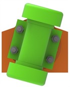
Fig. 2Structure of motor support
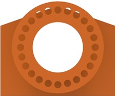
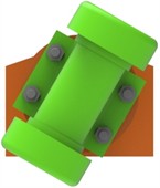
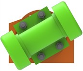
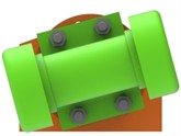
The bolt holes on the motor support are arranged in a circle. The angle between two adjacent bolt holes is 15°, and there are a total of 24 bolt holes. The vibrating motor is fixed to the bolt holes of the motor support by bolts. By changing the installation angle of the vibrating motor and fixing it to different bolt holes, the adjustment of the vibration direction angle is achieved. This adjustment method is simple and reliable. The installation and disassembly of the vibrating motor are easy, and the technical threshold is low. The vibrating motor is fixed by bolts and bolt holes, and the connection method is firm and reliable. During the operation of the vibrating screen, the position of the vibrating motor will not change, the vibration direction angle remains constant all the time, and the main screen body runs more smoothly.
Fig. 3Adjustment methods of the vibration direction angle (15°, 30°, 45°, 60°, 75°)

3. Dynamic analysis
In ANSYS Workbench, the finite element model of vibrating screen is established as shown in Fig. 4. When the vibration direction angles are set to 15°, 30°, 45°, 60°, and 75° respectively, the excitation force direction is configured correspondingly according to the schematic in Fig. 5. Dynamic analysis is then performed on the vibrating screen under these different vibration direction angles. Through this process, the displacement and stress distribution contour maps of the vibrating screen at its operating frequency are obtained, as illustrated in Fig. 6.
Fig. 4Finite element model of vibrating screen
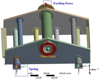
Fig. 5Settings of exciting force (15°, 30°, 45°, 60°, 75°)
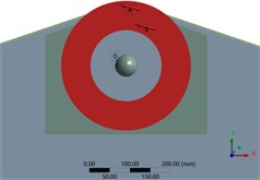
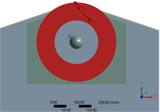
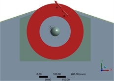

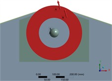
Fig. 6The displacement and stress distribution contour maps of the vibrating screen under different vibration direction angles
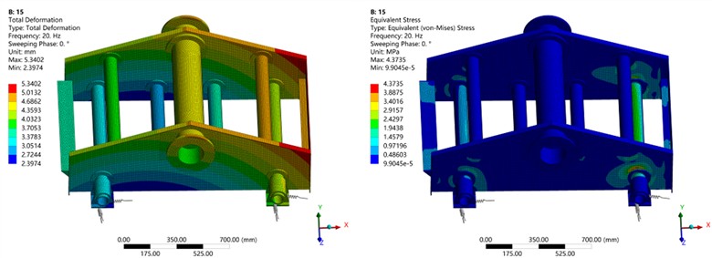
a) The vibration direction angle is 15°
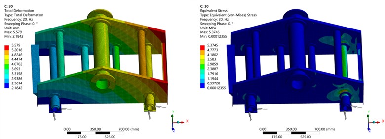
b) The vibration direction angle is 30°
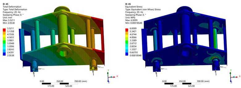
c) The vibration direction angle is 45°
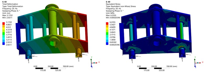
d) The vibration direction angle is 60°
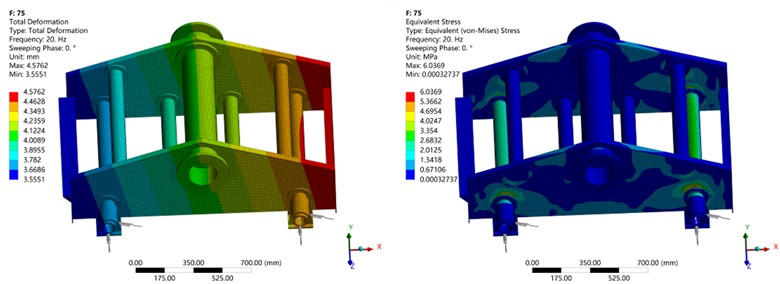
e) The vibration direction angle is 75°
From the displacement distribution contour maps, it can be observed that the vibrating screen performs linear motion under the excitation force. The displacement at the feed end exceeds that at the discharge end, indicating greater oscillation amplitude at the feed end during operation. This kinematic characteristic propels coal particles forward along the screen surface, facilitating material conveyance. The overall displacement of the vibrating screen ranges between 2-5 mm, with maximum displacements recorded at the rear baffle: 5.3402 mm (15°), 5.579 mm (30°), 5.5211 mm (45°), 5.1722 mm (60°), 4.5762 mm (75°). The screen’s center of mass, located at the vibration motor position, exhibits a displacement of approximately 3-4 mm, satisfying fundamental design specifications.
The stress distribution contour maps reveal principal stress concentrations at the feed-end side plate, specifically at the junction between the side plate and support beam. Peak dynamic stresses are measured as: 4.3735 MPa (15°), 5.3745 MPa (30°), 6.0099 MPa (45°), 6.2355 MPa (60°), 6.0369 MPa (75°). These values remain substantially below the yield strength of the structural steel employed. Other components demonstrate stress levels below 4 MPa, achieving safety factors exceeding 50. This stress profile confirms uniform load distribution, excellent structural integrity, and compliance with strength/stiffness requirements, ensuring resistance to deformation and fatigue failure during normal operation.
4. Conclusions
1) This study presents a new type of linear vibrating screen with an adjustable vibration direction angle. By changing the fixed positions of the bolts between the vibrating motor and the motor support, the angle between the vibration direction and the screen surface can be altered, thus achieving the adjustment of the vibration direction angle. This enables the vibrating screen to adapt to different working conditions, ensuring a good screening effect. The operation is simple, effective, and reliable.
2) This study conducted a dynamic analysis of a vibrating screen using Creo and ANSYS Workbench, investigating the displacement and stress distribution under different vibration direction angles. The results demonstrate that the vibrating screen operates smoothly with uniform load distribution across the screen body. All stress values remain within the material’s allowable stress limits, satisfying both strength and stiffness requirements of the structure. The rational structural design of this vibrating screen not only meets industry demands but also provides valuable references for the design of linear vibrating screens.
References
-
L. Peng et al., “A review on the advanced design techniques and methods of vibrating screen for coal preparation,” Powder Technology, Vol. 347, pp. 136–147, Apr. 2019, https://doi.org/10.1016/j.powtec.2019.02.047
-
Y. Zhao, J. Liu, X. Wei, Z. Luo, Q. Chen, and S. Song, “New progress in the processing and efficient utilization of coal,” Mining Science and Technology (China), Vol. 21, No. 4, pp. 547–552, Jul. 2011, https://doi.org/10.1016/j.mstc.2011.06.015
-
Y. M. Zhao, C. S. Liu, X. M. He, C. Y. Zhang, Y. B. Wang, and Z. T. Ren, “Dynamic design theory and application of large vibrating screen,” Procedia Earth and Planetary Science, Vol. 1, No. 1, pp. 776–784, Sep. 2009, https://doi.org/10.1016/j.proeps.2009.09.123
-
Z. Wang, C. Liu, J. Wu, H. Jiang, B. Song, and Y. Zhao, “A novel high-strength large vibrating screen with duplex statically indeterminate mesh beam structure,” Journal of Vibroengineering, Vol. 19, No. 8, pp. 5719–5734, Dec. 2017, https://doi.org/10.21595/jve.2017.18319
-
Z. Wang, X. Wang, J. Zhuang, Z. Kou, and C. Liu, “Multiple parameter collaborative optimization of a particle separation equipment for coal cleaning production,” Journal of Environmental Chemical Engineering, Vol. 9, No. 4, p. 105646, Aug. 2021, https://doi.org/10.1016/j.jece.2021.105646
-
H. Jiang et al., “Effect of excitation parameters on motion characteristics and classification performance of rigid-flexible coupled elastic screen surface for moist coal,” Advanced Powder Technology, Vol. 31, No. 3, pp. 1196–1208, Mar. 2020, https://doi.org/10.1016/j.apt.2019.12.029
-
Y. Wang, Z. Wang, M. Zhang, B. Xu, and Y. Song, “Dynamic characteristics analysis of a circular vibrating screen,” Vibroengineering Procedia, Vol. 48, pp. 22–28, Feb. 2023, https://doi.org/10.21595/vp.2022.23025
About this article

The research work is financially supported by the Natural Science Foundation of Shandong Province (ZR2023ME211), and College Students Innovation and Entrepreneurship Training Program of Linyi University (X202410452304), and Technology-based Small and Medium-sized Enterprises Innovation Capacity Enhancement Project of Shandong Province (2023TSGC0387).
The datasets generated during and/or analyzed during the current study are available from the corresponding author on reasonable request.
The authors declare that they have no conflict of interest.
