Abstract
Traditional slider-crank mechanisms transmit high loads through the mechanical structure, hindering the design of compact machines. The paper considers the dynamic behavior of a single-mass oscillatory system actuated by a slider-crank excitation mechanism. The research methodology involves mathematical modeling and computer simulation to analyze the trajectory and kinematic characteristics of the considered oscillatory system. The dynamic diagram of the single-mass vibratory system is considered, and the mathematical model describing its motion is derived using Euler-Lagrange equations. The obtained results show the time response curves of the oscillating mass plane-parallel motion under different excitation conditions, as well as the amplitude and phase responses as functions of frequency. The primary scientific novelty of this research is determining the influence of specific design parameters of the vibration exciter on the trajectory of the working member motion, as well as defining the stability of the response at different frequencies. The research highlights the possibility of generating circular, elliptical, and rectilinear vibrations of the working member depending on the specific operation, such as conveying, screening, sieving, or compacting. This adaptability is crucial for tailoring the system to different industrial applications and optimizing its performance for specific tasks.
Highlights
- The research analyzes the dynamics and stability of a single-mass oscillatory system driven by a slider-crank vibration exciter.
- Mathematical modeling and computer simulation demonstrate the ability to generate rectilinear, circular, and elliptical motion trajectories.
- Adjusting the slider-crank mechanism's geometric parameters controls the specific oscillation pattern produced by the working member.
- Frequency response and phase-plane analyses confirm the system's asymptotic stability and highlight the role of damping in controlling amplitude.
- The system's adaptability suits various industrial tasks like conveying, screening, or compacting by tailoring the vibration trajectory.
1. Introduction
The slider-crank mechanism offers a robust and efficient means of generating the reciprocating motion required for numerous industrial applications. The present paper investigates the dynamics and stability of a single-mass oscillatory system driven by a slider-crank vibration exciter. This mechanism finds widespread application in various fields, including vibratory conveyors [1, 2], vibration-driven robots [3, 4], capsule-type locomotion systems [5, 6], compacting machinery [7, 8], feeding and screening equipment [9, 10], etc. In [1], the authors presented a method for identifying parameters in vibratory conveying systems, considering the statistical behavior of conveyed parts. The paper [2] demonstrates the controlled transportation of objects on an inclined plane using oscillations and dynamic dry friction. The locomotion of a wheeled vibration-driven robot with an enhanced pantograph-type suspension is characterized in [3]. The paper [4] investigates the impact of gap value on the speed of a wheeled vibration-driven robot. The effectiveness of iterative and non-iterative Fourier series-based methods for optimizing the control of a discontinuous capsule drive are explored in [5]. The dynamics of a pipe robot with a vibration drive based on centrifugal forces is analyzed in [6]. In [7], the authors determined the inertia-stiffness parameters and developed a motion model for a three-mass vibratory system with a crank excitation mechanism. In [8], there is performed the kinematic and dynamic analysis of a three-mass vibratory system of a vibro-impact plate compactor with a crank-type excitation mechanism. The paper [9] is devoted to the development and experimental validation of a dynamic model for the motion analysis of a linear vibratory feeder. The paper [10] investigates the transient state behavior of a new drive system for a laboratory screen with rectilinear vibrations.
Previously considered research has explored different facets of slider-crank-driven oscillatory systems. Several studies have focused on the dynamic modeling and analysis of such systems, considering factors such as impact gaps [4, 5], inertia-stiffness parameters [6, 7, 8], and the influence of processed materials [9, 10]. Furthermore, the literature reveals investigations into the control and optimization of slider-crank-driven systems. In [11], the author delved into the nonlinear behavior of vibratory conveyors with single-mass crank-and-rod exciters, further emphasizing the importance of understanding the dynamic characteristics and stability boundaries of such systems. The paper [12] analyzes the dynamic behavior of a vibratory screening conveyor with a crank-type exciter. In [13], the author proposed a new type of vibration generator with a vibratory force oriented in a preferred direction. A rigid-flexible coupled dynamic model for a flip-flow vibrating screen, considering the effects of processed materials, is developed in [14]. The paper [15] analyzes the vibration characteristics of an industrial-scale flip-flow screen with a crank-link structure and optimized geometrical and inertia-stiffness parameters.
The stability of oscillatory systems is crucial for their reliable operation. In [16], the authors examined the Sommerfeld effect in an oscillator with a reciprocating mass, shedding light on potential stability issues. In [17], the authors introduced a controllable crank mechanism for the effective excitation of oscillations in vibratory equipment. The studies [18, 19] underscore the ongoing efforts to refine the performance and adaptability of the vibratory systems. The paper [18] conducted a dynamic analysis of a vibratory system with a twin crank-slider excitation mechanism, highlighting the complexities that arise with multiple degrees of freedom. In [19], the authors presented a trajectory-based synthesis methodology for determining the geometrical parameters of slider-crank mechanisms intended for actuating inertial vibration exciters.
While prior research has addressed various aspects of slider-crank-driven oscillatory systems, a comprehensive analysis of the dynamics and stability of a single-mass system with this type of excitation is still lacking. This paper aims to bridge this gap by developing a detailed dynamic model, conducting a thorough stability analysis, and providing insights into the system’s behavior under different operating conditions. The findings of this research will contribute to a deeper understanding of slider-crank-driven oscillatory systems and facilitate their optimized design and operation in diverse engineering applications, particularly conveying, screening, and sieving.
2. Research methodology
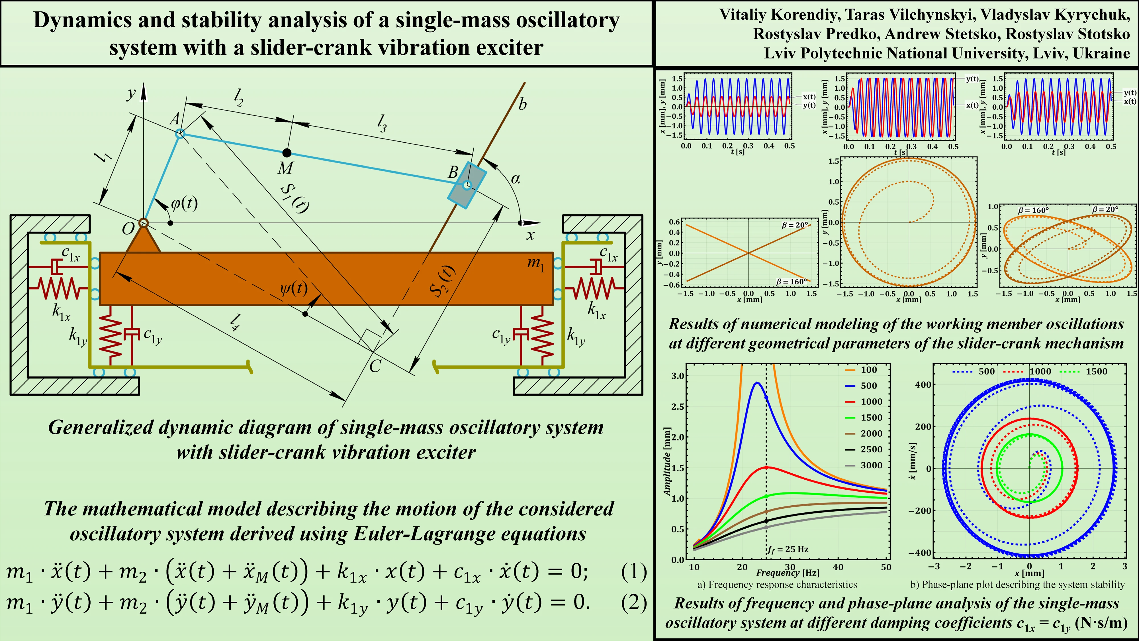
The generalized dynamic diagram of a single-mass oscillatory system actuated by the slider-crank vibration exciter is presented in Fig. 1. The system is considered to have three degrees of freedom described by three generalized coordinates: horizontal and vertical displacements of the oscillating mass – and , and controllable angular position of the crank – .
Fig. 1Generalized dynamic diagram of single-mass oscillatory system with slider-crank vibration exciter
The oscillating mass is represented by the large rectangular block defining the working member of a vibratory technological machine. This is the primary mass that undergoes oscillatory motion. It’s constrained to move primarily in the horizontal () and vertical () direction. The elastic supports defined by the stiffness coefficients and are represented by the horizontal and vertical springs connected to . They provide restoring forces in the - and -directions, resisting horizontal and vertical displacement of the working member, and responsible for the main oscillatory behavior of the mass . Damping elements defined by the viscous friction coefficients and are represented by the horizontal and vertical dashpots connected to . They represent viscous damping, providing resistance to motion proportional to velocity in the - and -directions. They absorb energy and dampen horizontal and vertical oscillations. The dashpots help control the amplitude and settling time of the horizontal and vertical oscillations.
The slider-crank excitation mechanism consists of the crank represented by the rotating link of length , connected to the origin () at a pivot joint. The link rotates with an angle , which varies with time, driving the whole system. Connecting rod is represented by the link of length (), connecting the crank to the slider. It transmits the motion from the crank to the slider. Point M, representing the unbalanced body (mass ), is located somewhere along at a distance from the hinge . Slider is represented by the block that moves along an inclined guide (line ). The angle of its inclination is . The slider’s motion is constrained to this guide.
Considering the masses of the mechanism’s links negligibly small compared to the masses of the working member and the unbalanced body , let us utilize the Euler-Lagrange principles to derive the differential equations describing the system motion:
where the coordinates and of the unbalanced body in the non-inertial reference frame related to the working member (mass ) are comprehensively described in [19]. Due to the extra-large expressions for Eqs. (1) and (2), let us omit their full presentations in this paper.
During further numerical modeling, let us consider the possibilities of generating rectilinear, elliptical, and circular oscillations of the working member (mass ) at different geometrical parameters of the considered slider-crank exciter. In addition, let us perform the stability analysis of the system’s oscillatory motion at various parameters of stiffness and damping.
3. Results and discussion
Let us further consider the same geometrical parameters of the slider-crank mechanism as the ones presented in [19]: 10 mm; 50 mm. In order to generate rectilinear oscillations at the inclination angles 20° (160°) with the horizontal axis, let us use the following parameters substantiated in [19]: 502 mm, 0 mm, 20° (160°). If it is necessary to excite circular oscillations, let us adopt the following parameters [19]: 0 mm, 61 mm, 0…180°. Considering the possibilities of generating an elliptical trajectory of oscillations of the working member, let us also analyze two cases [19]: the ellipse major axis is inclined at the angles 20° (160°) to the horizontal axis, where 234 mm, 156 mm, 22.9° (162.9°).
Considering the case when the corresponding stiffness and damping coefficients in horizontal and vertical directions are equal , the ratio of the active mass to the disturbing mass is equal to 10: (10 kg, 1 kg), and the necessary forced frequency 25 Hz, let us approximately determine the stiffness coefficients ensuring near-resonance oscillations (the natural frequency of the undamped vibrations is equal to the forced frequency):
Therefore, let us finally consider the over-resonance operational regimes by adopting 2.5∙105 N/m. In the next stage, let us analyze the conditions of the system’s oscillatory motion. The system is critically damped when the damping ratio Based on this, let us define the critical damping coefficients:
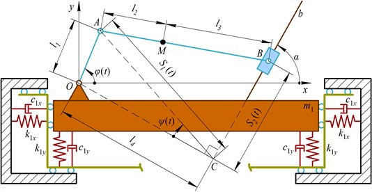
In order to perform further numerical modeling, let us adopt 103 N∙s/m. The modeling is carried out in the Wolfram Mathematica software by solving the system of differential Eqs. (1) and (2) with the help of the fifth-order Runge-Kutta methods. The upper plots in Fig. 2 show the time dependencies and of the working member horizontal and vertical displacements, respectively. In all the considered cases, the horizontal displacement ranges from approximately –1.5 mm to 1.5 mm, while the vertical displacement depends on the trajectories of the working member presented on the lower plots. As shown in Fig. 2, the working body can generate linear, circular, and elliptical oscillations under different geometrical parameters of the slider-crank excitation mechanism considered above and substantiated in [19]. In all the cases, the approximate peak-to-peak amplitude of oscillations is equal to 3 mm: for the linear path, this is the length of a segment connecting the endpoints of the path; for the circular trajectory, this is the diameter of a circle; for the elliptic path, this is the length of the ellipse’s major axis.
Fig. 2Results of numerical modeling of the working member oscillations at different geometrical parameters of the slider-crank excitation mechanism
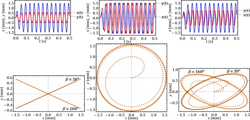
Let us further perform the frequency response analysis that evaluates how a single-mass oscillatory system responds to harmonic excitation at different frequencies (see Fig. 3(a)). This method reveals key characteristics, such as resonance, damping effects, and steady-state amplitudes, enabling engineers to predict system behavior and design appropriately. Orange, blue, red, and green curves exhibit the peaks, indicating resonance, where the system’s natural frequency matches the driving frequency, leading to the maximum amplitude of oscillations. Different curves represent varying levels of damping, achieved by changing the damping coefficients in the system within the range of 100…3000 N∙s/m. The curves with lower peaks (e.g., brown, black, gray) indicate stronger damping, which suppresses the amplitude at resonance and broadens the frequency response. The curves with higher peaks (e.g., red, blue, orange) represent weaker damping, leading to a sharper resonance peak and larger amplitudes near the resonant frequency. At the frequencies below resonance (less than 25 Hz), the amplitudes are relatively low and increase gradually as the frequency approaches resonance. At resonance, the amplitude reaches its maximum value, with the magnitude depending on the damping level. For example, in the case of 103 N∙s/m, the amplitude value of the working member displacement is approximately 1.5 mm, which corresponds to the results of numerical modeling.
At the last stage of this research, let us analyze a phase-plane plot, which shows the relationship between displacement (position) and velocity (speed) of a single-mass oscillatory system (see Fig. 3(b)). This type of plot is very useful for understanding the stability and dynamic behavior of the system. All three trajectories show spirals converging towards the origin (0, 0), which is characteristic of damped oscillations. This means the system loses energy over time due to the damping force. There is no indication of a limit cycle. The system eventually comes to rest at the equilibrium point. The fact that all trajectories converge to the origin indicates that the system is asymptotically stable. This means that regardless of the initial conditions, the system will eventually settle down to its equilibrium state. The three curves represent different damping coefficients (500, 1000, and 1500 N·s/m). The green trajectory (1500 N·s/m) shows the fastest decay, indicating the strongest damping. The blue trajectory (500 N·s/m) has the slowest decay, representing the weakest damping. The rate at which the spirals converge to the origin is directly related to the strength of the damping force. Higher damping leads to faster convergence.
Fig. 3Results of frequency and phase-plane analysis of the single-mass oscillatory system at different damping coefficients c1x=c1y (N·s/m)
a) Frequency response characteristics
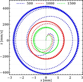
b) Phase-plane plot describing the system stability
By combining the insights from the frequency-response characteristics and phase-plane plots with the results of numerical modeling, a more complete understanding of the system’s stability and dynamic behavior can be achieved. This problem will be considered in further investigations on the subject of the present research combined with the experimental tests of the laboratory prototype of the slider-crank excitation mechanism implemented in a compacting machine.
4. Conclusions
The paper investigated the dynamics and stability of a single-mass oscillatory system driven by a slider-crank excitation mechanism. Through mathematical modeling and computer simulation, there was analyzed the system’s behavior under various operating conditions, focusing on the influence of design parameters on the trajectory and stability of the working member’s motion. The obtained findings demonstrate the ability of the system to generate diverse oscillation patterns, including rectilinear, circular, and elliptical trajectories, by adjusting the geometrical parameters of the slider-crank mechanism. This adaptability makes the system suitable for a range of industrial applications, such as conveying, screening, sieving, and compacting.
Furthermore, the carried-out frequency response and phase-plane analysis revealed the system’s stability characteristics under different damping conditions. The results highlight the importance of damping in controlling the amplitude of oscillations and ensuring stable operation, particularly near resonance frequencies. Future work will focus on experimental validation of the theoretical findings and further exploration of the system’s performance in specific applications, particularly in the context of a compacting machine.
References
-
S. Schiller, D. Perchtold, A. Eitzlmayr, P. Gruber, and D. Six, “Parameter identification of vibratory conveying systems including statistical part behavior,” Discover Mechanical Engineering, Vol. 3, No. 1, p. 22, Aug. 2024, https://doi.org/10.1007/s44245-024-00058-3
-
R. El Banna, K. Liutkauskienė, V. Lukoševičius, A. Fedaravičius, and S. Kilikevičius, “Transportation of objects on an inclined plane oscillating in the longitudinal direction applying dynamic dry friction manipulations,” Applied Sciences, Vol. 14, No. 11, p. 4474, May 2024, https://doi.org/10.3390/app14114474
-
V. Korendiy and O. Kachur, “Locomotion characteristics of a wheeled vibration-driven robot with an enhanced pantograph-type suspension,” Frontiers in Robotics and AI, Vol. 10, p. 12391, Aug. 2023, https://doi.org/10.3389/frobt.2023.1239137
-
V. Korendiy, O. Kachur, V. Gurskyi, and P. Krot, “Studying the influence of the impact gap value on the average translational speed of the wheeled vibration-driven robot,” Engineering Proceedings, Vol. 24, No. 1, p. 25, Sep. 2022, https://doi.org/10.3390/iecma2022-12897
-
S. Zarychta, M. Balcerzak, and J. Wojewoda, “Exploring iterative and non-iterative Fourier series-based methods of control optimization in application to a discontinuous capsule drive model,” Nonlinear Dynamics, Vol. 113, No. 3, pp. 2333–2353, Oct. 2024, https://doi.org/10.1007/s11071-024-10333-3
-
K. Ragulskis et al., “Investigation of dynamics of the pipe robot with vibration drive based on centrifugal forces,” Agricultural Engineering, Vol. 56, pp. 32–37, Jan. 2024, https://doi.org/10.15544/ageng.2024.56.5
-
V. Korendiy, O. Lanets, O. Kachur, P. Dmyterko, and R. Kachmar, “Determination of inertia-stiffness parameters and motion modelling of three-mass vibratory system with crank excitation mechanism,” Vibroengineering Procedia, Vol. 36, pp. 7–12, Mar. 2021, https://doi.org/10.21595/vp.2021.21924
-
V. Korendiy et al., “Kinematic and dynamic analysis of three-mass oscillatory system of vibro-impact plate compactor with crank excitation mechanism,” Vibroengineering Procedia, Vol. 40, pp. 14–19, Feb. 2022, https://doi.org/10.21595/vp.2022.22393
-
M. Buzzoni, M. Battarra, E. Mucchi, and G. Dalpiaz, “Motion analysis of a linear vibratory feeder: Dynamic modeling and experimental verification,” Mechanism and Machine Theory, Vol. 114, pp. 98–110, Aug. 2017, https://doi.org/10.1016/j.mechmachtheory.2017.04.006
-
J. Feliks, P. Tomach, D. Foszcz, T. Gawenda, and T. Olejnik, “Research on the new drive of a laboratory screen with rectilinear vibrations in transient states,” Energies, Vol. 14, No. 24, p. 8444, Dec. 2021, https://doi.org/10.3390/en14248444
-
G. F. Alışverişçi, “The nonlinear behavior of vibrational conveyers with single‐mass crank‐and‐rod exciters,” Mathematical Problems in Engineering, Vol. 2012, No. 1, p. 53418, Oct. 2012, https://doi.org/10.1155/2012/534189
-
O. Kachur and V. Korendiy, “Dynamic behavior of vibratory screening conveyor equipped with crank-type exciter,” in Lecture Notes in Mechanical Engineering, Cham: Springer Nature Switzerland, 2023, pp. 44–53, https://doi.org/10.1007/978-3-031-32774-2_5
-
V. V. Mikheyev, “New type of vibration generator with vibratory force oriented in preferred direction,” Journal of Vibration Engineering and Technologies, Vol. 6, No. 2, pp. 149–154, Jun. 2018, https://doi.org/10.1007/s42417-018-0025-4
-
D. Lin et al., “A rigid-flexible coupled dynamic model of a flip-flow vibrating screen considering the effects of processed materials,” Powder Technology, Vol. 427, p. 118753, Sep. 2023, https://doi.org/10.1016/j.powtec.2023.118753
-
H. Li, C. Liu, L. Shen, and L. Zhao, “Vibration characteristics of an industrial‐scale flip‐flow screen with crank‐link structure and parameters optimization,” Shock and Vibration, Vol. 2021, No. 1, p. 26126, Sep. 2021, https://doi.org/10.1155/2021/2612634
-
A. Sinha, S. K. Bharti, A. K. Samantaray, G. Chakraborty, and R. Bhattacharyya, “Sommerfeld effect in an oscillator with a reciprocating mass,” Nonlinear Dynamics, Vol. 93, No. 3, pp. 1719–1739, Apr. 2018, https://doi.org/10.1007/s11071-018-4287-x
-
O. Lanets, O. Kachur, V. Korendiy, and V. Lozynskyy, “Controllable crank mechanism for exciting oscillations of vibratory equipment,” in Lecture Notes in Mechanical Engineering, Cham: Springer International Publishing, 2021, pp. 43–52, https://doi.org/10.1007/978-3-030-77823-1_5
-
V. Korendiy, V. Gursky, P. Krot, and O. Kachur, “Dynamic analysis of three-mass vibratory system with twin crank-slider excitation mechanism,” Vibrations in Physical Systems, Vol. 34, No. 2, pp. 1–9, Jan. 2023, https://doi.org/10.21008/j.0860-6897.2023.2.26
-
V. Korendiy, T. Vilchynskyi, V. Lozynskyy, R. Kachmar, Y. Porokhovskyi, and R. Litvin, “Trajectory-based synthesis of a slider-crank mechanism for applications in inertial vibration exciters,” Vibroengineering Procedia, Vol. 56, pp. 176–182, Oct. 2024, https://doi.org/10.21595/vp.2024.24578
About this article

The authors have not disclosed any funding.
The datasets generated during and/or analyzed during the current study are available from the corresponding author on reasonable request.
The authors declare that they have no conflict of interest.
