Abstract
Vidrodiagnostics is one of the methods of monitoring and diagnosing the railroad track for defects and damages. Determination of vibration (dynamic) impact on the track from the rolling stock load is possible with the help of vibration sensors - velocimeters and accelerometers. The article presents the results of full-scale (operational) tests of reinforced concrete sleepers with different types of bonding on three sections of the railroad mainline. The dependences between the maximum amplitudes of vibration displacement, vibration velocity are determined. The purpose of this study was to identify the main causes of defects in reinforced concrete sleepers by vibrodiagostic method, to identify the greatest attenuation of vibrations of the track structure, damping of vibration from passing rolling stock and determination of the best dynamic operation of the track. This research will help further technological and economic development of railroads, as well as maintain safe operation of the main network of the Republic of Kazakhstan.
1. Introduction
Railroad track is a complex system including the base, subgrade, ballast, sleepers, connecting elements and rails [1], [2]. As a result of the dynamic impact of the load from the moving train, reinforced concrete sleepers can fail to withstand vibration, which leads to the appearance of both hidden and obvious defects, sometimes ending in their complete destruction [5]-[7]. This, in turn, has a direct impact on the economy, development and safety of railway infrastructure operation [8]-[10].
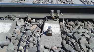
Specialists of the testing laboratory Testing of Track and Artificial Structures conducted full-scale experimental studies of three sections of the main network of JSC NC KTZh. Vibration diagnostic equipment was used on the basis of analog-to-digital converter (ADC) block of measuring module E14-440, which converts analog signal into digital one. Velocimeters MV-25D-V were used as sensors, which convert mechanical vibrations into electrical signals and serve to measure the vibration velocity [11]. The operating frequency range of vibration sensors is from 1 to 1000 Hz. The tests were conducted during daylight hours. The purpose of the tests was to identify the main causes of defects in reinforced concrete sleepers by vibrodiagostic method, to determine the greatest attenuation of vibrations in the elements of the track structure, damping of vibration from passing rolling stock and determination of the best dynamic operation of the track [10]-[13]. The obtained data are in full agreement with the data obtained from the results of track measuring car passage on the sections of track interface with different types of rail fasteners [13]. In the works of foreign [5], [6], [13] Russian [8], [1] and Kazakhstani [1]-[4], [7], [9]-[12], [14] specialists presented studies on calculations and experimental determination of amplitude-frequency characteristics of railroad track elements, confirming the adequacy of the results presented in this article.
2. Modeling and analysis of dynamic characteristics
In order to identify the peculiarities of the vibrational process of reinforced concrete sleepers with different types of rail fastenings and to compare the parameters of the response to the impact of rolling stock, in-situ measurements of the characteristics of vibrations were carried out at three sites of JSC NC KTZh:
Site No. 1. Experimental studies were carried out at the 269-270 kilometer section of the enlarged Ekibastuz track distance (ЕТP-30) of JSC NC KTZh. Coupling ZBR65-SH (269 km) and Pandrol Fastclip (270 km) of even track at the crossing Chiderty-Ekibastuz-1 (ЕТP-30): the section is double-track, the height of the embankment is 2.5 m, the width of the main platform is 9.6 m. The upper structure is represented by a trackless track made of R65 rails 250 m long on reinforced concrete sleepers (sleepers epature 1840 pcs/km). The rail-tie grid is laid on a ballast prism made of crushed stone. In plan the track is located on a straight section, electrified, the passed tonnage in 2023 was 305.4 million tons.km.br.
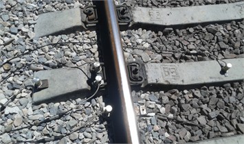
Fig. 1 shows a general view of the railroad track section at the Chiderty - Ekibastuz-1 crossing with vibration sensors installed.
Fig. 1General view of the track with vibration sensors installed
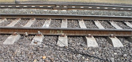
a) Pandrol Fastclip staple
b) ZBR65-S bonding staple
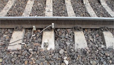
Site No. 2. Experimental studies were carried out at 4035-4036 kilometers of the ЕТP-46 section of JSC NC KTZh. Coupling of Vossloh W-14 (4035 km) and ZBR65-SH (4036 km) of even track at the Axenger crossing (ЕТP-46): the section is double-track, the height of the embankment is 1.65 m, the width of the main platform is 9.8 m. The upper structure is represented by a 350 m long track made of P65 rails on reinforced concrete sleepers (sleepers epature 1840 pcs/km). The rail-tie grid is laid on a ballast prism made of crushed stone. In plan the track is located on a straight section, electrified, the passed tonnage in 2023 was 207,8 million tons.km.br.
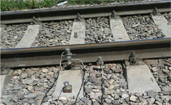
Fig. 2 shows a general view of the railroad track sections at the Axenger crossing with vibration sensors installed.
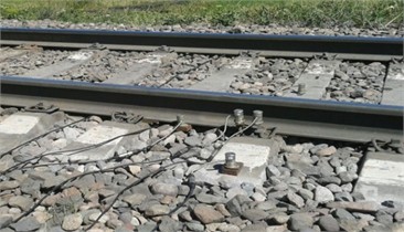
Site No. 3. Experimental studies were carried out at 4041-4042 kilometers of the ЕТP-46 section of JSC NC KTZh. Coupling of ZBR-65 (4041 km) and KB-65 (4042 km) of even track on the Aksenger-Burundai section (ЕТP-46): the section is double-track, the height of the embankment is 2.0 m, the width of the main platform is 12.5 meters. The upper structure is represented by a trackless track made of R65 rails 250 m long on reinforced concrete sleepers (sleepers epature 1840 pcs/km). The rail-tie grid is laid on a ballast prism made of crushed stone. In plan the track is located on a straight section, electrified, the passed tonnage in 2023 was 160.9 million tons.km.br.
Fig. 3 shows a general view of the railroad bed at the Burunday crossing with sensors installed.
Fig. 2General view of the track with vibration sensors installed
a) Vossloh W-14 staple
b) ZBR65-Sh staple
Fig. 3General view of the track with vibration sensors installed
a) with ZBR-65 fasteners
b) KB-65 fasteners
2.1. Test methodology
Dignostic parameters were measured and analyzed, and the attenuation coefficients of the amplitude vibration velocity amplitude of sleeper vibrations in relation to the vibration velocity of rail vibrations (, 1/m) and the area () of sleeper vibration velocity spectra (Ssh), characterizing the change in vibrational power, were determined in accordance with the recommendations [15, 16]. The area of the vibration velocity spectra of sleeper vibrations was calculated in the frequency range up to 20 Hz.
The law of vibration acceleration amplitude change is equal to the time derivative of the vibration velocity function:
where – is the instantaneous value of vibration acceleration.
The above equations show that there is an unambiguous mathematical relationship between the maximum amplitudes of vibration displacement, vibration velocity:
where and – respectively, the maximum value of vibration displacement amplitude and vibration velocity; – frequency of vibrations per unit time (technical frequency).
The attenuation coefficient of the amplitude vibration velocity amplitude of sleeper vibrations in relation to the vibration velocity of rail vibrations is determined by the formula:
where – amplitude of vibration velocity (the average value of the vibration range recorded under each axis of the rolling stock) at the rail sole; – amplitude of vibration velocity (the average value of the vibration range recorded under each axis of the rolling stock) on the middle of the sleeper.
For calibration of the mobile hardware-software complex was used installation based on the electrodynamic exciter ESE-201: Maximum permissible peak of vibration acceleration, 2-115 m/s; Acceleration conversion coefficient, about 25 m-s2/A; Natural frequency, about 30 Hz; Useful frequency range for comparative measurements without correction, 5-2000 Hz.
Main technical characteristics of vibration sensors MV-25D-V: Recorded frequencies, 1-1000 Hz; Recorded amplitudes of vibration displacements, 0,003-2 mm; Recorded amplitudes of vibration velocity, 3,85-314 mm/s; Recorded amplitudes of vibration accelerations, units. 0,5-10 g. The operating frequency range of vibration sensors is from 1 to 1000 Hz. According to the Kotelnikov-Naikvist-Shannon theorem, a signal can be restored accurately if it has a limited spectrum and the sampling frequency is at least twice the width of the signal spectrum. Thus, the 8000 Hz sampling frequency of the vibration measuring channel (respectively, the period of the sensor polling is 0.000125 s), adopted for recording and processing of the signal, allowed to make measurements with the help of the mobile hardware-software complex developed by the author with a 4-fold margin of the required accuracy. The use of such a high sampling frequency practically excluded the omission of peak values of the signal.
The measuring voltage converter E14-440D is designed for measuring DC and AC voltage: the limits of the tolerable systematic component of the error of DC voltage measurements in subranges: –2,5 V and 10 V = ±0,05 %; –0,6 V = ±0,1 %; –0,15 V = ±0,5 %. In-phase noise suppression coefficient, not less than – 70 dB.
3. Results of the study
Fig. 4 shows the oscillograms of vibration displacements of the sleeper middle for the track with Pandrol Fastclip and ZBR65-Sh fasteners, obtained under the influence of locomotive VL-80s at a speed of 95 km/h at 269-270 kilometers of the section of the enlarged Ekibastuz railway distance (ЕТP-30) of JSC NC KTZh.
Fig. 4Oscillograms of vibration displacements of the sleeper center with Pandrol Fastclip and ZBR65-Sh when passing VL-80s at a speed of 95 km/h
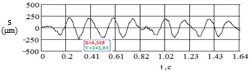
a)
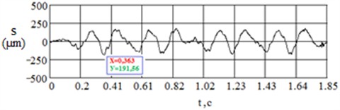
b)
Fig. 5 shows the graph of dependence of the coefficient of reduction of the amplitude vibration velocity amplitude of sleeper vibrations in relation to the rail from the speed of electric locomotive VL-80s and the diagram of the relationship between the total number of deviations of the 2nd degree and evaluation criteria obtained as a result of vibration diagnostics of the track top structure at the Chiderty - Ekibastuz kilometer 269-270.
In Figs. 6 and 7, graphs of spectral density of dispersion (spectra of vibration velocity and vibration displacement) of vibrations of the middle of the sleeper with fasteners Pandrol Fastclip (a) and ZBR65-Sh (b) at the passage of VL-80s with a speed of 95 km/h at the crossing Chiderty-Ekibastuz (ЕТP-30) at 269-270 km of even track.
Fig. 5Graph and diagram of vibrodiagnostics of track structure with Pandrol Fastclip and ZBR65-Sh on the Chiderty-Ekibastuz section, kilometer 269-270
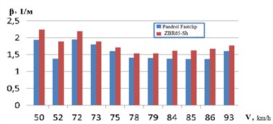
a) Graph of dependence of damping coefficient of amplitude vibration velocity amplitude of sleeper vibrations in relation to the rail
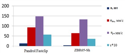
b) Diagram of vibrodiagnostics of track structure at section 1 (ЕТP -30)
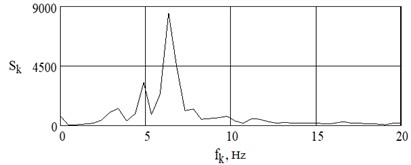
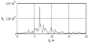
Fig. 6Vibration velocity spectrum of the sleeper middle vibrations at passing of VL-80s with the speed of 95 km/h on the Chiderty-Ekibastuz crossing (ЕРТ-30) at 270 km of even track
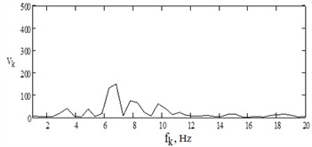
a)1.60, 1/m; Ssh = 5440 of units Pandrol Fastclip
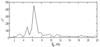
b)1,77, 1/m; Ssh = 11956 of units ZBR65-Sh
Fig. 7Spectrum of vibration displacement of vibrations of the middle of the sleeper during the passage of VL-80s with a speed of 95 km/h at the crossing Chiderty-Ekibastuz (ЕТP-30) at 270 km of even track

а) Pandrol Fastclip
b) ZBR65-Sh
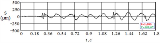
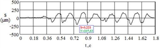
In Fig. 8 shows oscillograms of vibration displacements of the middle of the sleeper for the track with fasteners Vossloh W-14 and ZBR65-Sh, obtained during the movement of the locomotive VL-80s at a speed of 98 km/h at 4035-4036 kilometer crossing Aksenger section of the main line ЕТP-46 JSC NC KTZh.
Fig. 9 shows the graph of dependence of the coefficient of reduction of the amplitude vibration velocity amplitude of sleeper vibrations in relation to the rail on the speed of the electric locomotive VL-80s and the diagram of the relationship between the total number of deviations of the 2nd degree and the evaluation criteria obtained as a result of vibrodiagnostics of the track top structure at the 4035-4036 kilometer Axenger crossing.
In Figs. 10 and 11, the graphs of spectral density of dispersion (spectra of vibration velocity and vibration displacement) of vibrations of the middle of the sleeper with Vossloh W-14 (a) and ZBR65-Sh (b) fasteners at the passage of VL-80s with a speed of 98 km/h at the crossing Axenger (ЕТP -46) at 4035-4036 km of even track.
Fig. 8Oscillograms of vibration displacements of the sleeper middle with Vossloh W-14 and ZBR65-Sh when passing VL-80s at a speed of 100 km/h
a)
b)
Fig. 9Graph and diagram of vibrodiagnostics of track structure with Vossloh W-14 and ZBR65-Sh fasteners at 4035-4036 kilometer Axenger crossing
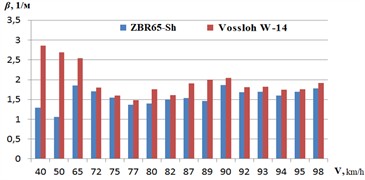
a) Graph of dependence of damping coefficient of amplitude vibration velocity amplitude of sleeper vibration in relation to the rail
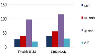
b) Diagram of vibrodiagnostics of track top structure on section 2 (ЕТP-46)
Fig. 10Vibration velocity spectrum of sleeper center vibrations at passing of VL-80s with the speed of 100 km/h
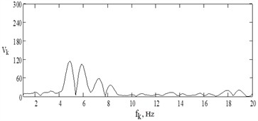
a)2,22, 1/m; Ssh = 13609 of units Vossloh W-14
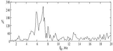
b)1,78, 1/m; Ssh = 49201 of unit ZBR65-Sh
Fig. 11Vibration displacement spectrum of the sleeper center vibration displacements during the passage of VL-80s at a speed of 100 km/h
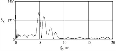
а) Vossloh W-14
b) ZBR65-Sh
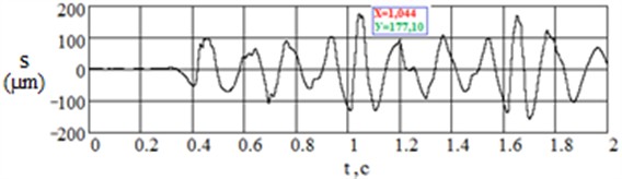
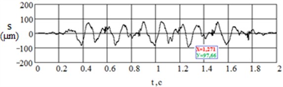
In Fig. 12 shows the oscillograms of vibration displacements of the middle of the sleeper for the track with fasteners KB-65 and ZBR-65, obtained during the passage of electric locomotive VL-80s at a speed of 105 km / h at 4041-4042 kilometers of the Aksenger - Burunday section of the main line ЕТP-46 JSC NK KTZh.
Fig. 12Oscillograms of vibration displacements of the sleeper’s middle with fastening ZBR-65 and KB-65 at passing of VL-80s at a speed of 105 km/h
a)
b)
Fig. 13 shows a graph of the dependence of the coefficient of reduction of the amplitude vibration velocity amplitude of the sleeper vibrations in relation to the rail on the speed of the electric locomotive and diagrams of the relationship between the total number of deviations of the 2nd degree and evaluation criteria obtained as a result of vibration diagnostics of the track structure at 4041-4042 kilometers on the Aksenger-Burunday crossing.
Fig. 13Graph and diagram of vibrodiagnostics of the upper track structure with fasteners KB-65 and ZBR65 at 4041-4042 kilometers on the Aksenger-Burunday crossing
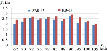
a) Diagram of dependence of the coefficient of attenuation of the amplitude vibration velocity amplitude of sleeper vibrations in relation to the rail
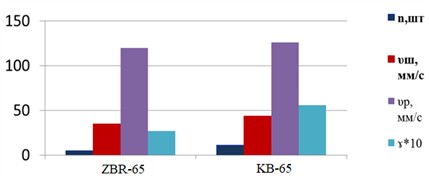
b) Diagram of vibrodiagnostics of the track top structure at section 3 (ЕТP-46)
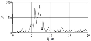
Figs. 14 and 15 show dispersion spectral density plots (vibration-velocity and vibration-displacement spectra) of vibrations of the sleeper middle with KB-65 (a) and ZBR65 (b) fastenings when passing overhead line 80s with a speed of 105 km/h at the Aksenger-Burunday (ЕТP-46) at 4041-4042 km of even track.
The results of investigations of mechanical vibrations of the middle and end of the reinforced concrete sleeper, arising during the movement of the locomotive VL-80s with different speeds in the range from 45 km/h to 105 km/h are presented in Tables 1 and 2.
Fig. 14Vibration velocity spectrum of sleeper center vibrations during the passage of VL-80s at a speed of 105 km/h
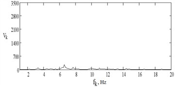
a)2,00, 1/m; Ssh = 12880 of unit KB-65
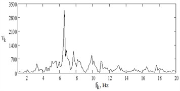
b)1,91, 1/m; Ssh =47575 of unit ZHBR-65
Fig. 15Vibration displacement spectrum of the sleeper middle vibrations during the passage of VL-80s at a speed of 105 km/h
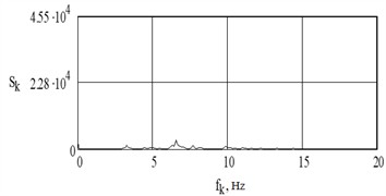
a) KB-65
b) ZHBR-65
Table 1Results of investigations of mechanical vibrations of the middle of the reinforced concrete sleeper arising during the movement of the locomotive VL-80s
, km/h | , µm | , µm | , Hz | , Hz | , Hz | |
45 | 22-34 | 11-13 | 0.25401-0.39256 | 2.9 | 29.4 | 318-534 |
50 | 26-33 | 11-14 | 0.3002-0.38102 | 3.1 | 33.1 | 330-453 |
55 | 29-55 | 17-19 | 0.33483-0.63503 | 3.3 | 35.1 | 411-551 |
60 | 54-77 | 28-32 | 0.5773-0.88904 | 3.8 | 40.3 | 450-597 |
65 | 62-84 | 31-35 | 0.71585-0.96986 | 4.1 | 43.6 | 540-651 |
70 | 64-128 | 40-65 | 0.73894-1.47789 | 4.3 | 5.4 | 426-626 |
75 | 86-137 | 50-62 | 0.99296-1.23542 | 4.6 | 5.8 | 510-587 |
80 | 86-126 | 54-63 | 0.99296-1.43171 | 5.0 | 6.2 | 431-594 |
85 | 122-146 | 68-87 | 1.40861-1.68572 | 5.3 | 6.6 | 548-734 |
90 | 128-187 | 80-115 | 1.47789-2.1591 | 5.6 | 7.0 | 538-626 |
95 | 141-182 | 92-124 | 1.62799-2.10137 | 5.9 | 7.3 | 529-600 |
100 | 137-181 | 63-106 | 1.5818-2.08983 | 6.2 | 7.7 | 482-651 |
105 | 158-196 | 89-131 | 1.82427-2.26302 | 6.3 | 7.9 | 529-600 |
4. Discussion of the results
Fig. 5 shows that the peak value of vertical vibration displacement of the sleeper center, for the track with Pandrol Fastclip (242.93 µm) was 21 % higher than the peak value of vertical vibration displacement of the sleeper center of the track with ZBR65-Sh (191.56 µm). Accordingly, the RMS value of vibration displacement obtained at the center of the sleeper for the Pandrol Fastclip track (102.09 µm) was 16 % higher than the RMS value for the ZBR65-Sh track (85.41 µm).
In Fig. 8, the peak value of the vertical vibration displacement of the sleeper mid-track, for the track with ZBR65-S (207.53 µm) was 24 % higher than the peak value of the vertical vibration displacement of the sleeper mid-track with Vossloh W-14 (158.07 µm). Correspondingly, the RMS value of the vibration displacement obtained at the center of the sleeper for the track with ZBR65-SH bonding (112.38 μm) was 30 % higher than the RMS value for the track with Vossloh W-14 bonding (79.03 μm).
Table 2Results of investigations of mechanical vibrations of the end of reinforced concrete sleeper arising during the movement of locomotive VL-80s
, km/h | , µm | , µm | , Hz | , Hz | , Hz | |
45 | 51-92 | 19-27 | 0.35533-0.64098 | 4.2 | 29.4 | 112-197 |
50 | 58-140 | 29-48 | 0.4041-0.97541 | 4.6 | 4.6 | 106-198 |
55 | 84-116 | 45-62 | 0.58524-0.80819 | 4.9 | 4.9 | 123-296 |
60 | 97-158 | 52-68 | 0.67582-1.10082 | 5.6 | 5.6 | 207-296 |
65 | 98-245 | 60-96 | 0.68278-1.70696 | 6.1 | 6.1 | 196-236 |
70 | 95-196 | 67-99 | 0.66188-1.36557 | 5.4 | 6.5 | 123-263 |
75 | 142-197 | 76-107 | 0.98934-1.37254 | 4.6 | 5.8 | 122-292 |
80 | 176-280 | 80-136 | 1.22622-1.95081 | 5 | 6.2 | 102-214 |
85 | 232-323 | 144-214 | 1.61639-2.2504 | 5.3 | 6.6 | 96-164 |
90 | 218-304 | 118-173 | 1.51885-2.11802 | 5.6 | 7 | 104-198 |
95 | 219-328 | 139-180 | 1.52581-2.28524 | 5.9 | 7.3 | 126-353 |
100 | 221-393 | 113-192 | 1.53975-2.7381 | 6.2 | 7.7 | 112-258 |
105 | 301-457 | 202-261 | 2.09712-3.184 | 6.3 | 7.9 | 94-133 |
Fig. 12 shows that the peak value of the vertical vibration displacement of the sleeper middle for the track with the fastener ZBR-65 (177.10 μm) was 45 % higher than the peak value of the vertical vibration displacement of the sleeper middle for the track with the fastener KB-65 (97.66 μm). Correspondingly, the RMS value of the vibration displacement obtained at the center of the sleeper for the track with ZBR-65 bonding (75.23 μm) was 34 % higher than the RMS value for the track with KB-65 bonding (49.32 μm).
From the diagrams presented in Figs. 6 and 7, 10 and 11, 14 and 15, it is evident that the parameters characterizing the change of vibrational power and vibration damping due to mechanical energy dissipation at the sections of track joints with different types of fastenings differ significantly.
The diagrams shown in Figs. 5, 9 and 13 show that the evaluation criteria adopted for vibration diagnostics adequately reflect the track condition determined by the results of the track measuring car passage.
Based on the above, it can be seen that the peak value of vertical vibration displacement of the sleeper center for Pandrol Fastclip (242.93 µm) was 21 % higher than that of ZBR65-SH (191, 56 μm), ZBR65-S (207.53 μm) was 24 % higher than Vossloh W-14 (158.07 μm), ZBR-65 (177.10 μm) was 45 % higher than KB-65 (97.66 μm). It can be concluded that KB-65 performs better than all tested bonds, then ZBR-65, after Vossloh W-14, then ZBR65-Sh, and worst of all Pandrol Fastclip.
5. Conclusions
The following conclusions can be drawn from the figures and tables presented in the research work: the greatest attenuation of vibrations, and, consequently, of the extinguished energy, obtained as the ratio of areas of spectral densities of power of vibrations on the rail and in the middle of the sleeper, is observed in the track with fasteners Pandrol Fastclip and Vossloh W-14 (respectively, 3,08 and 3,80), the attenuation coefficients of the amplitude of vibration velocity of vibrations of the rail in relation to the vibration velocity of vibrations of the sleeper (3,02 and 3,50) correspond to the ratio of areas of spectra.
From the analysis of the above results of vibrodiagnostics and the data of the technical condition of the railroad track according to the results of the track measuring car passage, it follows that the evaluation criteria obtained during the vibrodiagnostics of the track structure at the sections of the track interface with different types of rail fastenings adequately reflect the technical condition of the railroad track and agree with the point evaluation of the track according to the results of the track measuring car passage.
References
-
S. S. Abdullayev, I. S. Bondar, G. B. Bakyt, G. K. Ashirbayev, A. M. Budiukin, and Y. Y. Baubekov, “interaction of frame structures with rolling stock,” Series of Geology and Technical Sciences, Vol. 445, No. 1, pp. 22–28, Feb. 2021, https://doi.org/10.32014/2021.2518-170x.3
-
S. S. Abdullayev, G. B. Bakyt, M. N. Aikumbekov, I. S. Bondar, and Y. T. Auyesbayev, “Determination of natural modes of railway overpasses,” Journal of Applied Research and Technology, Vol. 19, No. 1, pp. 1–10, Mar. 2021, https://doi.org/10.22201/icat.24486736e.2021.19.1.1487
-
N. M. Makhmetova, M. Y. Kvashnin, and N. M. Kvashnin, “Investigation of free oscillations of the elements of the track upper structure with the fastening of the KPP-5 type,” Engineering Technologies of materials, pp. 38–42, 2013.
-
S. A. Burombaev, M. Y. Kvashnin, I. S. Bondar, and A. M. Zhangabylova, “Amplitude-frequency characteristics of track structure with fasteners of KPP-5 type under impact,” in International Scientific and Practical Conference Dedicated to the 135th Anniversary of M. Tynyshpayev “Transport in the XXI Century State and Prospects”, pp. 195–200, 2014.
-
K. G. Rustamovich, “Clamping force of intermediate fasteners and their determination.,” Journal NX, Vol. 7, No. 5, pp. 233–236, 2021, https://doi.org/10.17605/osf.io/etjhf
-
Begmatov N. I. and Muhammadiyev N. R., “Experimental determination of the rigidity of a rail thread,” Railway Transport: Current Challenges and Innovations, Vol. 3, No. 1, pp. 5–11, Jan. 2021, https://doi.org/10.24412/2181-953x-2021-1-5-11
-
Zhangabylova A. M., Bondar I. S. S., and Kvashnin M. Ya, “Analysis of the work of intermediate rail fasteners under the operational load,” Bulletin of KazATK, Vol. 133, No. 4, pp. 55–65, Apr. 2024, https://doi.org/10.52167/1609-1817-2024-133-4-55-65
-
S. A. Kosenko, I. S. Bondar, M. Y. Kvashnin, and G. I. Chekmareva, “Ensuring the passage of freight trains with increased axle loads on railway bridges,” Transportation Research Procedia, Vol. 61, pp. 627–635, Jan. 2022, https://doi.org/10.1016/j.trpro.2022.01.101
-
A. Akbayeva et al., “Development of safety methods on artificial structures of railway lines,” Eastern-European Journal of Enterprise Technologies, Vol. 6, No. 1(120), pp. 43–52, Dec. 2022, https://doi.org/10.15587/1729-4061.2022.269964
-
I. S. Bondar, D. T. Aldekeyeva, and Z. K. Ospanova, “Stress-strain states of reinforced concrete spans of a railroad overpass using a spatial finite element model,” in Vibroengineering Procedia, Vol. 54, pp. 320–326, Apr. 2024, https://doi.org/10.21595/vp.2024.24086
-
I. S. Bondar, M. Y. Kvashnin, N. M. Makhmetova, and A. M. Zhangabylova, Experimental Diagnostics of Intermediate Rail Fastenings. Almaty: KazATK, 2021.
-
I. S. Bondar, G. B. Karibaeva, and A. K. Kurbenova, “Vibration diagnostics of transportation structures on railroads,” Vibroengineering Procedia, Vol. 54, pp. 109–115, Apr. 2024, https://doi.org/10.21595/vp.2024.24093
-
K. S. Lesov and H. G. A. Rustamovich, “Calculation and assessment of stability of the rail tape of the jointless track for the conditions of Uzbekistan,” Online Scientific and Practical Journal of Sustainability and Leading Research, pp. 339–343, 2022.
-
Bondar I. S., Ospanova Z. K., Kvashnin M. Y., Kurmashev B. B., and Dzhazykpaeva E. E., “Determination of time resistance to rupture of steel reinforcement,” Vestnik KazATK, Vol. 131, No. 2, pp. 118–127, 2024, https://doi.org/10.52167/1609-1817-2024-130-1-118-127
-
E. S. Ashpiz, “Instruction on vibrodiagnostics of embankments on weak bases,” JSC Russian Railways, Moscow, Dec. 2012.
-
E. S. Ashpiz, “Instruction for vibration diagnostics of high embankments on railroads of JSC Russian Railways,” JSC Russian Railways, Moscow, Oct. 2014.
About this article

The authors have not disclosed any funding.
The authors would like to express their gratitude to S. A. Burombaev and S. T. Baimagambetov of JSC NC KTZh Almaty track distance (ЕТP-46) and S. T. Baimagambetov of Ekibastuz track distance (ЕТP-30) for the opportunity and assistance in the organization of field studies.
The datasets generated during and/or analyzed during the current study are available from the corresponding author on reasonable request.
The authors declare that they have no conflict of interest.
