Abstract
This study develops a comprehensive model that integrates the vibration source, building structure, and surrounding soil layers. The methodology involves a vertical vehicle-track coupling dynamic model and a multi-scale coupled finite element model encompassing moving loads, track structure, building body, and surrounding strata. The results show that vibrations induced by trains operating on the first level remain within acceptable limits. However, when trains operate simultaneously on both the first and second levels, vibration levels in the overlying structure exceed specified standards. Further targeted design optimizations are recommended.
Highlights
- Develop a comprehensive model that integrates the vibration source, building structure, and surrounding soil layers
- Vibrations induced by trains operating on the first level remain within acceptable limits
- It provides valuable insights and serves as a reference for similar engineering projects
1. Introduction
In the context of rapid global urbanization, the vertical integration of rail transit systems with architectural spaces has emerged as a critical strategy for high-density urban development [1]. By 2025, multiple cities in China have adopted the TOD (Transit-Oriented Development) model [2], characterized by “metros traversing through building floor slabs”. Notably, projects utilizing second-layer structural slabs as carriers for metro lines are increasingly prevalent. While this innovative design effectively conserves land resources, it introduces unique challenges related to vibration transmission [3]. Specifically, the structural slabs function both as the foundation for train operations and as the primary conduit for transmitting vibration energy upward into the building [4]. Empirical data indicate that when an A-type metro train travels at 80 km/h over a 300 mm thick concrete slab, the peak vibration acceleration on the slab surface can reach 1.5 m/s2, which is 4-6 times higher than in traditional underground tunnel scenarios [5]. Furthermore, the main vibration frequency band (20-80 Hz) overlaps significantly with the natural frequencies of buildings, leading to incidents such as glass curtain wall resonance fractures.
A recent study by He et al. [6] presented an efficient prediction model for vibrations induced by underground railway traffic, validated through experiments. Their model integrated a simplified numerical approach with key parameters of the railway system, ground, and tunnel structure, achieving high prediction accuracy. Another hybrid approach by Xin et al. [7] used an improved LSTM network combined with spectral analysis to predict subway-induced vibrations. The results showed significant improvements in prediction accuracy compared to traditional methods. Feng et al. [8] conducted in-situ experiments to investigate the influence of structural characteristics on subway-induced building vibrations. They concluded that vibration mitigation techniques such as floating slab tracks and resilient materials can effectively reduce vibration propagation. Additionally, Yang et al. [9] analyzed the dynamic response of subway tunnels under combined seismic and train-induced loads, proposing mitigation measures to protect surrounding structures.
Existing research addressing this issue still exhibits significant theoretical gaps [10]. Traditional vibration propagation theories, which are based on the assumption of a semi-infinite space, fail to account for the standing wave effects and modal superposition phenomena in finite boundary floor slabs. For instance, Forrest’s cylindrical wave model predicts an attenuation rate of 8 % per meter for vibrations in underground tunnels; however, in actual floor slab conditions, the vibration energy attenuates at only 2-3 % per meter due to multiple reflections. Additionally, current vibration isolation technologies primarily focus on underground structures, such as laminated rubber bearings, which achieve less than 35 % vibration reduction efficiency in plate-connected buildings and may also introduce secondary structural noise issues.
This study aims to overcome these limitations by developing a comprehensive model that integrates the vibration source, building structure, and surrounding soil layers. The proposed methodology will enable the transition from train dynamic simulation to building response prediction, thereby accurately predicting the vibration impacts of train operations and investigating feasible vibration mitigation measures. Unlike existing models that treat subsystems in isolation, our methodology explicitly couples the dynamic load from train operations with the structural response of the building and soil, enabling holistic vibration transmission analysis. This research will provide valuable insights and serve as a reference for similar engineering projects.
2. Train-track coupling dynamics model
To achieve precise simulation of the dynamic response of the track system induced by train operations, a vertical vehicle-track coupling dynamic model was developed, as shown in Figs. 1 and 2. This model comprises two main subsystems: the vehicle and the track, with dynamic coupling realized through the wheel-rail contact interface. The modeling process focuses on a subway train as the research subject, with its mass distribution and suspension parameters detailed in Table 1. Track system parameters are specified in Table 2.
Fig. 1Train model
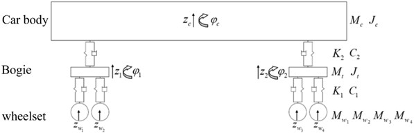
Fig. 2Track model

Table 1Vehicle dynamics parameters
Content | Vehicle |
Wheelbase of the bogie | 2300 mm |
Vehicle gauge | 12600 mm |
Length of the vehicle | 19520 mm |
Body mass | 42600 kg |
Body rotational inertia | 1262000 kg∙m2 |
Second-axle suspension stiffness | 0.48 kN/mm |
Second-axle suspension damping | 60 kN∙s/m |
Bogie mass | 2550 kg |
Bogie rotational inertia | 2410 kg∙m2 |
First-stage suspension stiffness | 1.5 kN/mm |
First-stage suspension damping | 5 kN∙s/m |
Wheelset mass , , , | 1760 kg |
Table 2Track dynamics parameters
Content | Value |
Elastic modulus of rail | 2.06×10¹¹ N/m² |
Unit mass of rail | 50 kg/m |
Rail density | 7850 kg/m3 |
The stiffness of common fasteners | 60 MN/m |
Fastener damping | 5×10⁴ N·s/m |
Fastener spacing | 0.6m |
Track gauge | 1435 mm |
Fig. 3Counterforce of fasteners
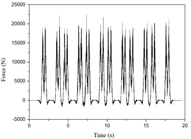
The calculated reaction forces of the fasteners are shown in Fig. 3.
The vehicle subsystem employs rigid multi-body dynamics modeling, incorporating three primary mass units: the car body, bogie, and wheelset. These components are interconnected via two suspension systems: the primary suspension simulates the vertical stiffness and damping characteristics between the wheelset and bogie, while the secondary suspension models the dynamic interaction between the bogie and car body.
The track subsystem is modeled using hierarchical discretization principles. The steel rail is represented as a finite-length Euler beam element, while fasteners, sleepers, and ballast are treated as equivalent spring-damper elements. The connection stiffness between the rail and sleeper is determined by the elastic properties of the fasteners, and the interaction between the sleeper and ballast is simulated through discrete support points.
The wheel-rail coupling mechanism is based on Hertzian nonlinear elastic contact theory. At the contact interface, random track irregularities generated from the US fifth-level spectrum are introduced as time-domain samples, with short-wave irregularity components superimposed to serve as external excitation sources. The dynamic equations are solved using a two-stage decoupling strategy, as outlined in Eq. (1):
3. Establishment of three-dimensional finite element model of building structure
To precisely simulate the entire process of building vibration transmission caused by subway operation, a multi-scale coupled model encompassing moving loads, track structure, building body, and surrounding strata was developed. The spatial coordinate system is defined as follows: the -axis aligns with the track extension direction, the -axis is perpendicular to the track, and the -axis represents the vertical direction. An explicit dynamic analysis method was employed, with a global integration step size of 0.001 seconds to ensure numerical stability for high-frequency vibration wave propagation.
For the simulation, a running condition of 25 km/h was selected, where both the first and second floors have active metro operations. The track structure employs an unreinforced crushed stone ballast bed. The steel rails are 50 kg/m standard sections, modeled using Euler-Bernoulli beam elements with an elastic modulus of 210 GPa and Poisson’s ratio of 0.3. The fastening system is simplified into linear spring elements with a stiffness of 60 MN/m, uniformly distributed at intervals of 0.625 m along the -axis at the sleeper support points. The substructure beneath the tracks is simulated using solid elements, with material properties corresponding to C50 concrete (density 2500 kg/m³, elastic modulus 34.5 GPa). The time history data of the fastener reaction forces from the vehicle-track coupling model in Fig. 3 are mapped to the moving load boundary conditions via the user-defined subroutine VDLOAD, accurately reproducing the dynamic interaction between wheel and rail.
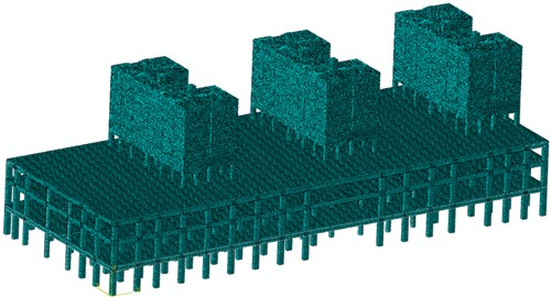
A typical area measuring 152.5 m () × 62 m () was chosen to construct the building body model, covering the full spatial extent of the cover plate. The beam-column system is modeled using three-dimensional beam elements, with main beams sized 800×1200 mm and columns with a diameter of 1000 mm. The material constitutive model assumes elastic behavior. The floor structure is discretized using S4R shell elements, with a thickness of 300 mm and a reinforcement ratio of 1.8 %. The final comprehensive model in Fig. 4 was built, treating the decoration layer and equipment loads as equivalent distributed surface loads using the additional mass method.
Fig. 4Overall finite element model of the building structure
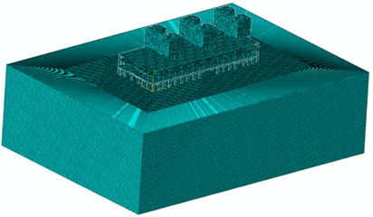
Based on the geological exploration report, the soil strata were systematically stratified. A three-dimensional finite element domain measuring 248 m () × 152 m () × 45 m () was established, as illustrated in Fig. 5. The modified Mohr-Coulomb model was employed to characterize the nonlinear behavior of the soil. The density, elastic modulus, and shear wave velocity parameters for each layer are detailed in Table 3. To mitigate wave reflection distortion caused by artificial truncation boundaries, an infinite element boundary layer was implemented around the model.
Table 3Physical and mechanical parameters of soil layers
Soil layer | Thickness / m | Density / g/cm³ | Wave speed / m/s |
Clayey fill soil | 3.6 | 1.85 | 148.95 |
Medium-coarse sand | 2.8 | 2 | 166.52 |
Silt-clay | 4.3 | 2.00 | 175.09 |
Sandy clayey soil | 6.4 | 1.85 | 189.67 |
Fully weathered mixed granite | 5.8 | 1.91 | 317.75 |
Strongly weathered mixed granite | 12.4 | 1.95 | 426.68 |
Medium weathered mixed granite | ∞ | 2.62 | 1009.04 |
The integrated finite element model of the track structure, building structure, and surrounding soil layer after construction is presented in Fig. 5.
Fig. 5Integrated finite element model of the track structure, building structure, and surrounding soil layer
4. Model validation
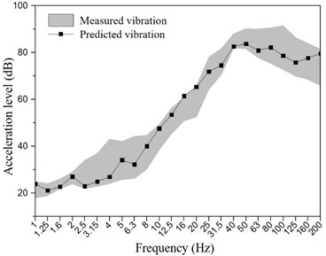
To validate the accuracy of the proposed model and method, a finite element model comprising the structure, building structure, and surrounding stratum was developed based on the actual conditions of the field test. The simulation results were then compared with the measured data. Fig. 6 compares the measured and calculated values of the vertical acceleration of floor vibration at a measuring point 8 m from the track centerline when the train speed is 5 km/h. It can be observed that the levels of vertical acceleration, dominant frequencies, and overall trends are generally consistent. Therefore, it can be concluded that the finite element numerical model accurately captures the vibration characteristics induced by subway train operations.
Fig. 6Comparison between measured and predicted vibration values
5. Results
Through finite element analysis, the areas most affected by the turnout regions were selected for detailed examination. Specifically, the rooms directly above the tracks and the locations with the highest vibration levels in bedrooms on each floor were analyzed. Considering the train running on the first floor (with vibration isolators having a vertical stiffness of 0.02 N/mm3), the predicted 1/3 octave band vibration acceleration levels are shown in Fig. 7. The results indicate that when the train operates on the first floor, the vibration levels in the overlying building remain within acceptable limits.
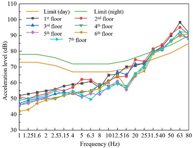
Considering the train operation on the second floor (without vibration damping measures) and the unfavorable scenario of train operation on the depot line on the first floor, the 1/3 octave band vibration acceleration levels resulting from the simultaneous operation of trains on both floors were calculated. The results are shown in Fig. 8. It is observed that at frequencies of 50 Hz and 63 Hz, the vibration levels in each floor exceed the nighttime limit values.
Unlike conventional single-source superposition, the dual-layer configuration amplifies vibration transmission through structural resonance, as the combined excitation frequencies (20-80 Hz) align with building modes. This phenomenon is distinct from linear superposition due to modal coupling and wave reflection/attenuation differences in finite slab structures. For instance, energy attenuation rates in our model differ significantly from semi-infinite space predictions. For the practical implications of the double-layer track superposition effect, the observed 2-3 % per meter energy attenuation rate (Fig. 8) will be contextualized against traditional metro systems (typically 5-8 % per meter), highlighting the unique challenges of multi-layer track configurations.
Fig. 7Prediction results of vibration of the upper cover residential buildings caused by the operation of the train on the first floor
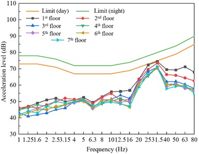
Fig. 8Prediction results of vibration in upper cover residential buildings
6. Conclusions
This study establishes an integrated model that incorporates the vibration source, buildings, and surrounding soil layers to achieve a comprehensive method for predicting building responses based on train dynamic simulations. The analysis predicts the vibration impacts caused by train operations and yields the following conclusions:
1) The vibrations induced in the overlying structure by trains operating on the first level remain within permissible limits.
2) When trains operate simultaneously on both the first and second levels, the vibrations in all floors of the overlying structure exceed the specified standards.
3) To ensure the comfort of residents in the overlying structure, it is recommended that vibration mitigation measures be implemented on the second-level tracks. These measures may include vibration isolators, resilient fasteners, and steel spring floating slabs. Further targeted design optimizations are necessary.
References
-
Y. Qiu, C. Zou, J. Wu, Z. Shen, and Z. Zhong, “Building vibration measurements induced by train operation on concrete floor,” Construction and Building Materials, Vol. 394, p. 132283, Aug. 2023, https://doi.org/10.1016/j.conbuildmat.2023.132283
-
S. Huang, Y. Chen, C. Zou, and S. Jian, “Train-induced environmental vibrations by considering different building foundations along curved track,” Transportation Geotechnics, Vol. 35, p. 100785, Jul. 2022, https://doi.org/10.1016/j.trgeo.2022.100785
-
Z. Tao, C. Zou, Y. Wang, and J. Wu, “Vibration transmissions and predictions within low-rise buildings above throat area in the metro depot,” Journal of Vibration and Control, Vol. 29, No. 5-6, pp. 1105–1116, Dec. 2021, https://doi.org/10.1177/10775463211057644
-
Z. Tao, Z. Hu, G. Wu, C. Huang, C. Zou, and Z. Ying, “Train-induced vibration predictions based on data-driven cascaded state-space model,” Buildings, Vol. 12, No. 2, p. 114, Jan. 2022, https://doi.org/10.3390/buildings12020114
-
X. Li, Z. Hu, and C. Zou, “Noise annoyance and vibration perception assessment on passengers during train operation in Guangzhou Metro,” Environmental Science and Pollution Research, Vol. 29, No. 3, pp. 4246–4259, Aug. 2021, https://doi.org/10.1007/s11356-021-15896-x
-
C. He, S. Zhou, H. Di, and X. Zhang, “An efficient prediction model for vibrations induced by underground railway traffic and experimental validation,” Transportation Geotechnics, Vol. 31, p. 100646, Nov. 2021, https://doi.org/10.1016/j.trgeo.2021.100646
-
T. Xin, Y. Yang, X. Zheng, J. Lin, S. Wang, and P. Wang, “Time series recovery using adjacent channel data based on LSTM: A case study of subway vibrations,” Applied Sciences, Vol. 12, No. 22, p. 11497, Nov. 2022, https://doi.org/10.3390/app122211497
-
F. Shijin, L. Fuhao, Z. Xiaolei, D. Guowei, and L. Jianping, “In-situ experimental investigation of the influence of structure characteristics on subway-induced building vibrations,” Earthquake Engineering and Engineering Vibration, Vol. 20, No. 3, pp. 673–685, Jul. 2021, https://doi.org/10.1007/s11803-021-2046-3
-
J. J. Yang, S. Y. Zhu, and W. M. Zhai, “Prediction and mitigation of train-induced vibrations of large-scale buildings constructed on subway tunnels,” Science of the Total Environment, Vol. 668, 2019.
-
P. Wang, Y. Wang, C. Zou, and J. Guo, “A preliminary investigation of noise impact within metro stations in the urban city of Guangzhou, China,” Environmental Science and Pollution Research, Vol. 24, No. 12, pp. 11371–11382, Mar. 2017, https://doi.org/10.1007/s11356-017-8776-0
About this article

The authors have not disclosed any funding.
The datasets generated during and/or analyzed during the current study are available from the corresponding author on reasonable request.
The authors declare that they have no conflict of interest.
