Abstract
The study of the resistance of the bulldozer blade burial at a stationary machine is aimed at studying the force factors acting on the working tool during its penetration into the ground. When the machine is not moving, the blade deepening causes an increase in passive resistance from the ground, which acts on the front and rear edges of the blade. This resistance increases with the depth of burial, which requires an increase in force for further advancement of the working body into the ground. An important feature is that in the initial stages of blade insertion, the resistance at the front face increases significantly, increasing the forces. At the rear edge, the re-sistance also increases as the blade deepens. Cutting angles have a significant effect on resistance changes: at higher cutting angles, the resistance decreases, reducing the load on the working mechanisms. The results of the study emphasize that for efficient knife deepening with the machine stationary, higher cutting angles should be used, which reduces passive resistance, improving productivity and reducing energy costs.
Highlights
- Dependence of die settlement on load.
- Slip lines in the ground under the knife.
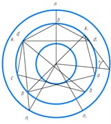
- Pressing the knife into the ground.
- Sliding surfaces in the ground during knife indentation with cutting angle.
1. Introduction
Analysis of the bulldozer working process and the influence on its efficiency of the kinematics of the working movements of the bulldozer equipment, as well as the design features of the base tractor. A promising direction of research is the creation of working bodies with the properties of wide adaptation to the types and conditions of work performed. In the case of bulldozers this tendency can be traced in the creation of designs of the bulldozer equipment suspension, allowing to change the cutting angle in the process of digging the soil. At the same time, the used schemes of bulldozer equipment suspension are usually structurally similar, regardless of the layout of the base tractor. However, the bulldozer efficiency is influenced not only by the kinematic parameters of the bulldozer blade suspension and traction qualities of the base machine taken separately, but also by the consistency of their joint work.
One of the directions of expanding the area of application and increasing the efficiency of earthmoving machines without increasing the capacity of the base machine is to reduce specific energy consumption for the performance of technological operations [1].
When improving existing machines, in particular bulldozers, this direction, based on the realization of rational design and operating parameters, seems to be more preferable.
According to the theory of soil cutting by blade-type working bodies, it is necessary to create bulldozer equipment that realizes the necessary force at a rational cutting angle.
Thus, to develop soils of different categories it is advisable to have bulldozer equipment with variable cutting angle.
Currently, there are known hangers of bulldozer equipment, in which the change of the cutting angle of the ground is carried out with the help of a hydraulic cylinder-strut, but they are not widely used because of the significant complication of the design associated with the use of an additional power drive.
The above stated determines the relevance of the topic of work aimed at improving the design of the suspension of bulldozer equipment with variable cutting angle. Therefore, justification of rational kinematic parameters of the bulldozer working equipment suspension with variable cutting angle is an urgent task [1-3].
The novelty of the conducted research lies in the substantiation of rational kinematic parameters of the suspension of the working equipment of the bulldozer with variable cutting angle, aimed at improving energy efficiency and expanding the technological capabilities of the machine without increasing the power of the base tractor. The improved method of calculation of resistance forces from the ground at the blade cutting is offered, based on the use of graph-analytical method of S.S. Golushkevich taking into account the real conditions of the stressed state of the soil massif. It is established that the increase in the cutting angle contributes to a significant decrease in the forces of passive resistance on the part of the soil, especially on the rear and lower edges of the knife, which leads to a decrease in specific energy consumption when performing technological operations. The obtained results can be used in the design of adaptive working bodies of earthmoving machinery.
2. Methods
Deepening of the bulldozer blade into the ground with the machine stationary can be visualized as pressing into the soil mass of a die having a complex shape, which is subject to the force developed by the drive mechanism [1]. Under the action of the gravity of the working body and the force developed by the drive mechanism, stresses arise in the soil massif under the knife, the magnitude and distribution of which depend on the load, geometric parameters of the knife and soil parameters. If we take an area of limited dimensions, tightly adjacent to the soil surface, called in soil mechanics a die, and stepwise increase the load on it, measuring the settlement S after each application of load, then the graph of the dependence of the die settlement on the load has the form shown in Fig. 1 [1, 2]. Three phases can be distinguished on the graph, proceeding sequentially and differing in the nature of movements of the deformed soil. In the first phase, there is an almost exclusive compaction of the soil under load, with the soil particles mostly sinking downwards. The corresponding section of the 0-a settlement curve for dense soils is close to a straight line. The settlement corresponding to the first phase, the compaction phase, is usually small. As the load increases further, along with continued soil compaction, the phenomenon of soil squeezing out from under the die becomes more and more important due to the occurrence of shear and plastic flow in some points of the soil. The second phase of deformation corresponds to the section of the curve a-b. As the load increases, the settlement becomes more and more irregular. When the load reaches a certain critical value, shear zones gradually formed in the soil merge to form a continuous sliding surface, along which the soil evaporates from under the die, accompanied by its sharp sinking (section of the curve b-c). A compacted core is formed under the die, pushing the soil apart as the die subsides. The subsidence occurs almost instantaneously. The transition from one stage of deformation to another, especially from the second to the third, is not sharply pronounced. Therefore, the distinction between them is made conditionally. The operation of a soil massif under conditions of significant development of plastic deformation zones in the soil and transition to the third phase of deformation according to [2] can be evaluated by the design scheme of a half-space under the conditions of limit equilibrium.
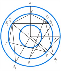
Three characteristic stressed zones and areas can be distinguished in the soil massif covered by shear under the die (Fig. 2): I – region of the highest stresses; II – special region; III – region of the lowest stresses. The directions of sliding surfaces, along which the shear occurs, can be determined using the characteristic circles of S. S. Golushkevich [2]. As it is known, this construction allows us to find the direction of sliding surfaces of the ground passing through the ends of the given site, if we know: the angle of internal friction of the ground , specific cohesion and the direction of the total stress or pressure acting on this site .
Fig. 1Dependence of die settlement on load
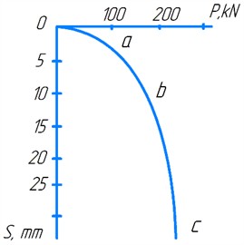
Fig. 2Slip lines in the ground under the knife
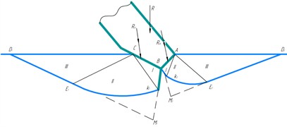
a) Scheme
b) Characteristic circle system
Assuming that at some moment of the knife penetration the ground is in the ultimate stress state, it is possible to determine the value of the ultimate load (pressure) on the array from the side of the knife edges, corresponding to the bearing capacity of the ground. When the knife is pushed in, its faces, penetrating into the array, create a stressed state in the ground. Considering the knife faces as retaining walls pushing on the soil massif, and likening the soil resistance to compression to passive soil rebound, we determine the value of passive soil resistance acting on the knife faces [2].
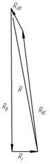
The pressure exerted on the retaining wall by the bulk solid as it moves toward the bulk solid at the initial moment of formation of continuous slip surfaces is called passive resistance or soil rebound. A prism of soil bounded by a bulk slip surface is called a prism of bulge. The simplest and the most simple and illustrative way to determine the values of passive soil rebound acting on the retaining wall is the graphical method of S. S. Golushkevich. Knowing the parameters of soil and knife, we build a system of characteristic circles and determine the directions of sliding areas in the soil and the pressure on the knife edge separately for each edge (Fig. 3) [2, 3]. After determining the value of the passive ground pressure acting on the knife faces AB and BC, we determine the value of the external force necessary for deepening the knife into the massif.
Let’s determine the initial direction of sliding areas B in the ground and the value of passive rebound in the ground for the face BC (Fig. 3). We construct a rectangular triangle of arbitrary dimensions, one of the angles of which is equal to , and use this triangle to represent the system of characteristic circles (Fig. 3(b)). Let us draw a tangent BC to the circle of squares parallel to BC. Through the point of tangency BC with the circle of platforms and the center of the circle O we draw a straight line up to the intersection with the circle of poles at the point . From the point parallel to the force acting on the knife edge we draw a straight line up to the intersection with the vertex circle. Since the passive ground repulsion acts on the edge BC, the line of action of the force deviates from the normal to the edge BC by the angle of external ground friction . Since within the area there is a maximally stressed state, connecting the points and with the point , we obtain the direction of slip lines and (Fig. 3(b)). Drawing the lines : and parallel to the lines and , we obtain the region of the highest stresses (Fig. 3(a)) [4-7].
Fig. 3Pressing the knife into the ground
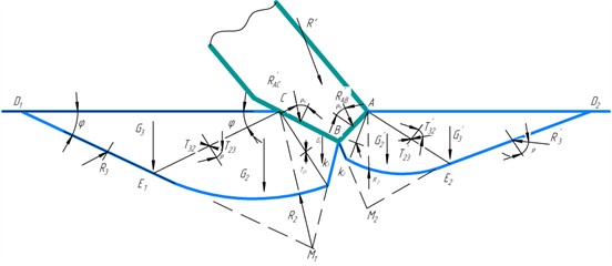
a) Scheme
b) Characteristic circle system
c) Power polygons
d) Power polygons
e) Power polygons
We assume that only uniformly distributed normal load – cohesion pressure , equal to:
Then the slip lines within this area will be straight lines inclined to the ground surface at an angle of:
Having drawn a straight line through the point C at an angle to the ground surface, we determine the position of the point on it, denoting the length of the segment by . The length of the radius – vector , determining the position of point , is found from the expression:
where r_1 – CK segment length; – angle formed by lines and ; – base of natural logarithms.
The length and angle are calculated by direct measurement on the diagram constructed according to Fig. 3. Having thus determined the position of the point , we draw through it the straight line , inclined to the ground surface at an angle . The special region II is closed by the curve , outlined by a logarithmic spiral. This completes the construction of the calculated slip line.
Let us consider the forces applied to the prism formed by the face СВ of the blade cutting element. Within the area, the forces shown by solid lines in Fig. 3, a are applied: the external force component acting on the blade face ; the gravity force of the soil of zone I, for the determination of which it is necessary to calculate the volume of the prism :
where – volumetric weight of soil; – free fall acceleration; – drawing prism volume СВК1.
Unknown in magnitude ground reaction , applied to face , and inclined at an angle to the normal; unknown in magnitude ground mass reaction , inclined to plane at an angle ; binding pressure , applied normal to plane СВ and equal to:
where – blade length.
Within area II, the forces shown by the dotted line in Fig. 3, are applied: the ground gravity force of area II, for the determination of which it is necessary to calculate the volume of the prism :
where – area of the sector of the logarithmic spiral; unknown in value forces of interaction with zones I and III, denoted in the figure by and , applied to faces , and inclined to the corresponding normals at angles equal to ; unknown in value reaction of the soil mass , the direction of which is assumed to coincide with the straight line [4-7].
Within area III, the following forces are applied: the ground gravity force of area III, for the determination of which it is necessary to calculate the volume of prism :
where – prism volume .
Unknown in value force , representing the force of interaction of zones II and III, inclined to the normal at an angle ; unknown in value reaction of the soil mass , inclined at an angle to the normal; cohesion pressure , applied normal to the plane and equal to:
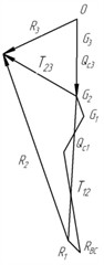
Having determined the magnitude and direction of the above mentioned forces, let’s construct the polygon of forces for zone III, then let’s construct the polygon of forces for zone II and then for zone I (Fig. 3(c)). As a result, we obtain the value of passive ground resistance acting on the edge of the knife – .
Determination of the direction of the slip areas and the value of passive ground support for the AB face starts with the construction of the calculated slip line. Let’s draw a tangent line to the circle of platforms parallel to AB (Fig. 3(b)). Through the point of tangency of the line ab with the circle of platforms and the center of the circle O we draw a straight line up to the intersection with the circle of poles – point . From the point , parallel to the force acting on the face AB, we draw the line to the intersection with the circle of vertices. Since the passive ground repulsion acts on the face AB, the line of action of the force deviates from the normal to the face AB by the angle . Connecting the points and with the point , we obtain the direction of the slip line. By drawing the lines and parallel to the lines and , we obtain the area of the highest stresses (Fig. 3(a)). By drawing the lines and parallel to the lines and , we find the direction of the slip lines of region III. The point - the end of the radius – vector is found from Eq. (3). In this case the angle , . Closing the special region II by the curve , outlined by the logarithmic spiral, we obtain the special region .
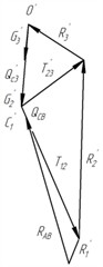
The forces applied to the notch prism are similar to the forces applied to the notch prism . The order of determination of the force. is similar to the order of determination of the force . We construct force polygons and determine the magnitude of the passive ground rebound acting on the face AB – (Fig. 3(d)). Knowing the magnitude and direction of the ground resistance forces and , we find the magnitude and direction of the resultant ground resistance force (Fig. 3(e)), which can be decomposed into horizontal and vertical components. By applying to the knife an external force , equal and opposite to the force , it is possible to push the knife into the ground by a certain amount. If , the ultimate stress state will not be created in the massif and the knife will not go deep.
3. Results and discussions
The area of contact of the BC face with the ground gradually increases with the indentation, while the AB face stabilizes from the depth of (Fig. 4). As the area of contact between the face and the ground increases, the volume of the bulge prism increases, and, consequently, the amount of force required to create the ultimate stress state in the ground. The value of the vertical pressure is determined according to the dependence:
where – vertical component of the resultant ground reaction force acting on the knife edge; – projection of the bottom surface of the blade, which is in contact with the ground, on the horizontal plane.
Fig. 4Sliding surfaces in the ground during knife indentation with cutting angle
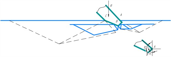
a) Cutting angle 45°
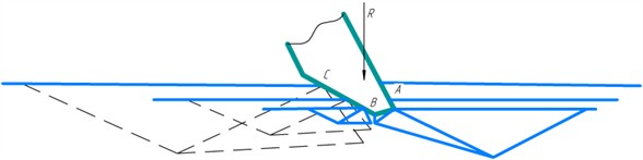
b) Cutting angle 70°
The change of value with increasing in the process of indentation changes insignificantly. The exception is the initial section up to 3 mm, which is explained by the nature of the change in the forces and (Fig. 5).
Analysis of the available data [4, 5] allows us to say that the cutting angle also affects the resistance to knife burial. As the angle increases from 45 to 70°, the passive resistance acting on the knife faces and decreases nonlinearly, and the one acting on the face BC more intensively (Fig. 6). If at 45° and 10 mm 24350 N, 5530 N, then at 70° and 10 mm 7953 N, 2100 N.
Fig. 5Variation of vertical indentation from knife indentation value
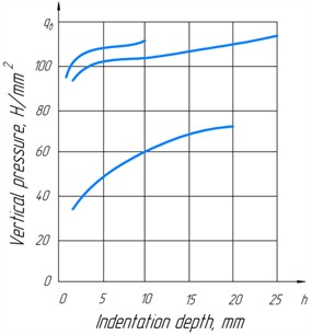
Fig. 6The effect of cutting angle on the components of the soil rebound at knife indentation depths of 10 mm (--------) and 5 mm (- - - - - -): RAB – force acting on edge AB; RBC – force acting on the BC face; RB – vertical component of the resultant force; Rr – horizontal component resultant force
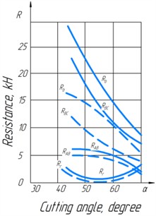
Thus, increasing the cutting angle from 45 to 70° (1.56 times) reduced by 3.06 times and by 2.63 times. This is explained by the fact that with the increase of the angle of inclination of faces AB and BC to the horizon changes, the area of contact of the face with the ground changes, the volume of the protrusion prism and, as a consequence, the value of the passive ground resistance acting on the knife edge decreases. With the increase of the cutting angle, the specific vertical pressure of the knife on the ground changes, which decreased for the considered case in 1.78 times at 10 mm.
Reduced by 3.6 times and by 2.63 times. This is explained by the fact that with increasing , the angle of inclination of faces AB and BC to the horizon changes, the area of contact between the face and the ground changes, the volume of the protrusion prism changes, and, as a consequence, the value of passive ground resistance acting on the knife edge decreases. As the cutting angle increases, the specific vertical pressure of the knife on the ground changes, which decreased for the case under consideration by a factor of one at 10 mm.
To confirm the reliability of the results obtained in the course of theoretical modeling of the process of bulldozer blade deepening into the soil massif, experimental studies were conducted in laboratory conditions. The experiments were conducted in the laboratory of field soil research (Department of “Motor vehicles and life safety”), using a specially prepared stand (Fig. 7). The medium density loam with the following physical and mechanical characteristics was used as the medium under study: internal friction angle 28°, specific cohesion 18 kPa, specific weight 18.5 kN/m3. The object of research was a knife with width 800 mm and cutting edge length 300 mm. During the tests, the cutting angle α was varied, taking values of 45°, 60° and 70°, which allowed us to study the influence of this parameter on the value of the burial force. To measure the forces, a strain gauge was used, which was mounted on the rod of the hydraulic cylinder providing the knife movement. Signals from the sensor were recorded using the NI DAQ system with a sampling frequency of 100 Hz, which made it possible to obtain accurate and reliable values of forces in the process of burial.
Table 1 below shows the experimental and calculated values of burial force at different cutting angles and knife depths, as well as the errors between them.
Fig. 7Stands for research of bulldozer working processes on physical models of working bodies
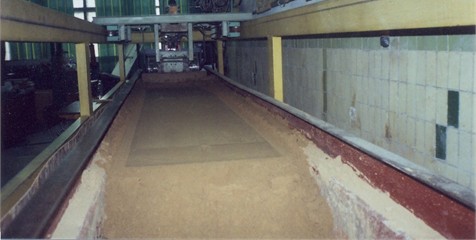
Table 1Experimental results
Cutting angle | Depth of burial , mm | Deepening force , N | Model force , N | Uncertainty, % |
45° | 10 | 29 500 | 30 200 | 2.4 |
60° | 10 | 19 200 | 18 750 | 2.3 |
70° | 10 | 11 300 | 11 650 | 3.1 |
45° | 5 | 15 700 | 15 300 | 2.5 |
60° | 5 | 10 200 | 10 050 | 1.5 |
70° | 5 | 5 800 | 5 950 | 2.6 |
The results of the experimental studies demonstrate a good correspondence between the theoretically calculated and actually measured values of the knife penetration force into the soil massif. The average error between the calculated and experimental data does not exceed 3 %, which indicates the high accuracy of the proposed model. To confirm its reliability, comparative tests were carried out, including both laboratory experiments on physical models and field studies. Comparison of the results of numerical modeling with the data obtained during field and laboratory tests showed a high degree of convergence: the deviations do not exceed 10 %, which is within the permissible engineering limits and can be explained by both experimental errors and approximate assumptions of the mathematical model. Thus, we can conclude that the developed model has a high degree of reliability and can be effectively used for predicting the behavior of the soil when the working body of the bulldozer plunges. This is especially important when designing earthmoving equipment and selecting its operating modes in various operating conditions.
The proposed model considers the soil as a homogeneous isotropic medium in the limit equilibrium under static flat blade indentation. However, simplified representation of real soil properties (without taking into account thixotropy, moisture content) and idealization of the blade geometry are limitations. The graph-analytical method has subjectivity and dependence of accuracy on the constructions. The model does not account for dynamic loads and vibrations generated by the bulldozer. These assumptions and limitations should be considered when interpreting the modeling results and applying them to practical problems.
4. Conclusions
Deepening of the bulldozer's working body into the ground can be considered as pressing a complex-shaped die into the soil mass, which is subjected to the force developed by the drive mechanism. Under the influence of the gravity of the implement and the force generated by the drive mechanism, stresses are generated in the soil massif on both sides of the blade faces (front and rear), the magnitude and distribution of which depend on the load, geometric parameters of the belt and soil characteristics. The forces acting on the knife edge during indentation are determined by the method of S. S. Golushkevich.
The increase in the cutting angle leads to a decrease in the projection of the indented part of the blade on the horizontal plane, which, in turn, reduces the area of contact with the soil and the volume of the protrusion prism. This leads to an increase in the specific vertical pressure of the blade on the ground and a decrease in its resistance to penetration. Consequently, for effective deepening of the bulldozer’s working body when the machine is stationary, it is necessary to use a larger cutting angle.
A study of the effect of cutting angle on bulldozer efficiency shows a significant improvement in productivity and reduction in energy consumption when the cutting angle is increased. Increasing the cutting angle leads to a decrease in soil resistance forces, which in turn reduces the energy requirement for earthmoving operations. This is confirmed by both theoretical calculations and laboratory test results. The method of calculation of resistance forces based on graph-analytical method of S. S. Golushkevich allows to take into account more accurately the real conditions of soil work and optimize the design of bulldozer working bodies. Improved kinematics of working movements and adaptation of bulldozer equipment suspension with variable cutting angle allow to increase the overall efficiency of the machine, reduce the load on the engine and, as a consequence, reduce fuel costs. Thus, the use of variable cutting angle and optimization of the working elements significantly increase the energy efficiency and productivity of the bulldozer.
References
-
D. P. Volkov, Machines for Earthworks. Moscow: Higher School, 2012.
-
S. S. Golushkevich, Statistics of Limit States of Ground Masses. Moscow: Gostekhizdat, 1957.
-
D. Sharma and N. Barakat, “Evolutionary bi-objective optimization for bulldozer and its blade in soil cutting,” Journal of The Institution of Engineers (India): Series C, Vol. 100, No. 2, pp. 295–310, Feb. 2018, https://doi.org/10.1007/s40032-017-0437-z
-
Kozbagarov R. A., Zhusupov K. A., Kaliev E. B., Yessengaliyev M. N., Kochetkov A. V., and Kamzanov N. C., “Development of control suspension of attachment of a bulldozer,” NEWS of National Academy of Sciences of the Republic of Kazakhstan, Vol. 4, No. 442, pp. 166–174, Aug. 2020, https://doi.org/10.32014/2020.2518-170x.97
-
R. Kozbagarov, M. Amanova, N. Kamzanov, L. Bimagambetova, and A. Imangaliyeva, “Investigation of wear of cutting part of polygonal knife car graders in different ground conditions,” Communications – Scientific letters of the University of Zilina, Vol. 24, No. 4, pp. D229–D238, Oct. 2022, https://doi.org/10.26552/com.c.2022.4.d229-d238
-
C. Miao, “Modeling and simulation research on the hydraulic system of the blade of an unmanned bulldozer,” Frontiers in Computing and Intelligent Systems, Vol. 11, No. 2, pp. 78–82, Feb. 2025, https://doi.org/10.54097/n8pphn83
-
A. Mathur et al., “A comprehensive review of bulldozers in modern construction,” Journal of Scientific Research and Reports, Vol. 30, No. 5, pp. 337–342, Mar. 2024, https://doi.org/10.9734/jsrr/2024/v30i51949
About this article

The authors have not disclosed any funding.
Authors express our gratitude to the management of the University named after M. Tynyshbaev for assistance in conducting scientific work.
The datasets generated during and/or analyzed during the current study are available from the corresponding author on reasonable request.
The authors declare that they have no conflict of interest.
