Abstract
This study investigates the excessive cable forces observed in a double-tower prestressed concrete (PC) cable-stayed bridge during its operational phase. Comparative analysis between field-measured data and design specifications reveals that the actual bearing capacity of multiple stay cables significantly exceeds the code-specified allowable limits, compromising structural safety requirements. A finite element model was established using Midas Civil software, leveraging operational monitoring data to simulate the bridge construction process. The analysis specifically investigated the effects of girder self-weight variations, prestressing force adjustments, and main beam alignment changes on cable force distribution patterns. The numerical analysis demonstrates that beam self-weight augmentation and main beam alignment alterations collectively account for 62.3 % of the total measured cable force increment, representing the primary contributing factors. In contrast, the impact of prestressed over-tension and subsequent loss (maintaining less than 10 % variation) on cable forces was found to be statistically insignificant, suggesting these parameters have minimal influence on the overall cable force distribution pattern.
Highlights
- Stay cables' load capacities exceed code limits, revealing safety risks.
- Twin-tower long-span cable-stayed bridge mechanics systematically investigated.
- win-tower long-span cable-stayed bridge mechanics systematically investigated.
1. Introduction
Cable-stayed bridges have gained widespread application in modern bridge engineering owing to their structural elegance, remarkable spanning capabilities, economic efficiency, and superior environmental adaptability. During the operational phase of the cable-stayed bridges, subject to complex influences from multiple factors, including traffic loading patterns, concrete shrinkage and creep phenomena, and environmental conditions, all of which substantially affect structural stress distribution and linear variations. Previous research has established that critical parameter deviations, particularly in main beam concrete over-pour, prestress application, and cable force distribution, significantly impact bridge performance [1]-[5]. While Liang et al. [6] demonstrated through comparative analysis that variations in tower or beam stiffness exhibit minimal influence on deformation patterns and internal force distribution in long-span cable-stayed bridges, Hassan et al. [7] extended this understanding by examining the effects of main span cable-free zone length and stiffness variations in structural components on girder stress characteristics. Complementing these findings, Bao et al. [8] employed numerical simulation techniques to perform parameter sensitivity analysis, revealing the critical influence of cable force, deck pavement thickness, and concrete creep coefficient on main beam stress and displacement during the operational phase.
This study focuses on a prestressed concrete beam semi-floating system cable-stayed bridge featuring double towers and double cable planes, with particular emphasis on investigating the underlying causes of excessive cable forces during the operational stage. The research aims to establish a comprehensive theoretical framework for understanding the mechanisms behind elevated cable forces in this specific bridge type.
2. Project profile
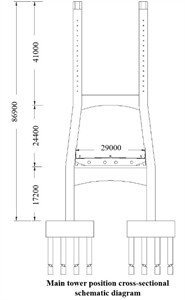
The investigated structure is a double-tower, double-cable-plane PC beam semi-floating system cable-stayed bridge with a span arrangement of 84 m + 200 m + 84 m. The upper structure is a single-box four-chamber precast concrete box girder with a width of 29 m. The structural system consists of 62 intermediate beams and 4 end beams, with intermediate beams strategically positioned at each stay cable-main beam intersection and end beams located at the piers and towers. All beams are constructed using C50 grade concrete with a comprehensive prestressing system: the main beam features bidirectional prestressing, while the cross beam incorporates transverse prestressing. The prestressing system employs 15Φs15.24 and 19Φs15.24 steel strands, with the Φs15.24 strands exhibiting a standard tensile strength of 1860 MPa and the rolled-threaded rebars demonstrating 930 MPa tensile strength. The bridge’s “H” type portal towers, featuring box-shaped thin-walled structures, stand at 86.9 m (north) and 82.6 m (south) respectively. The stay cable system utilizes double-layer PE low-stress anti-corrosion hot-dip galvanized semi-parallel steel wires with an ultimate tensile strength of 1670 MPa, comprising a total of 120 cables (15 per side per tower column), as illustrated in Fig. 1.
Fig. 1Diagram of bridge layout (unit: mm)
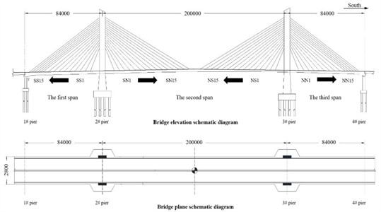
a) General structural diagram
b) Cross section diagram
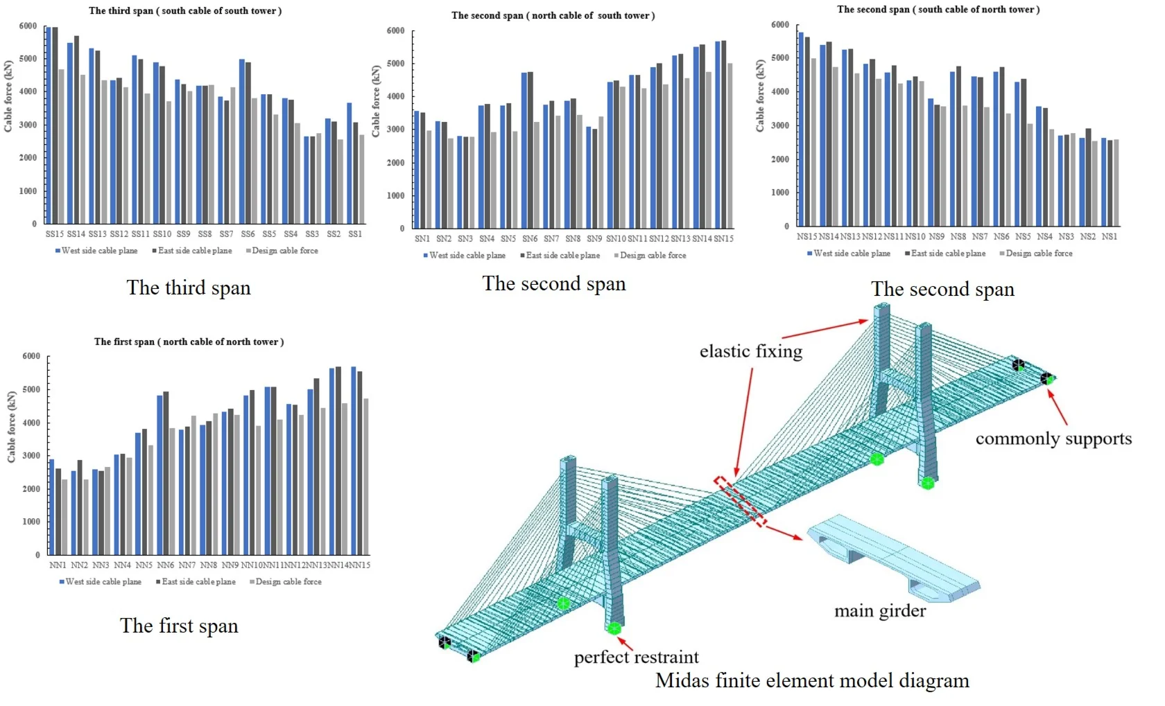
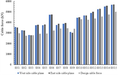
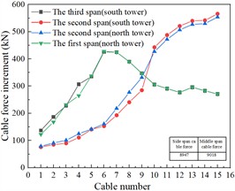
Operational testing revealed significant cable force deviations, as depicted in Fig. 2. The measured cable forces consistently exceeded design values, with 80 stay cables (66.7 % of total) showing forces greater than 110 % of design specifications. The deviation range spanned from –9.8 % to +9.7 %, with an average deviation of 15.0 %, resulting in a cumulative measured cable force exceeding design value by 65951 kN. Structural assessments indicated no significant cracking in tower beams despite these elevated forces. Displacement measurements showed a 3.6 cm reduction in mid-span elevation compared to design values, while side span alignment remained consistent with design specifications. Cross-sectional measurements revealed reduced box dimensions, contributing to an actual structural weight approximately 7.1 % greater than design calculations.
Cable force distribution serves as a crucial parameter for assessing bridge condition rationality, directly influencing main tower and beam internal forces. While main beam alignment and tower deviation remain within design specifications, the observed global cable force deviations are primarily attributed to beam weight variations, prestress deviations, and main beam alignment changes. Given the absence of construction monitoring and completion data, this study employs a comprehensive approach combining field test data, bridge design documentation, and finite element simulation analysis to investigate the underlying causes of excessive cable forces, considering potential parameter deviations and their cumulative effects on structural behavior.
Fig. 2Comparison of measured and designed cable forces
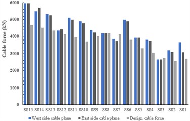
a) The third span
b) The second span
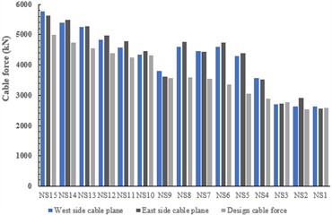
c) The second span
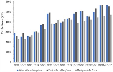
d) The first span
3. The finite element model calculation
To systematically investigate the underlying causes of excessive cable forces in the bridge structure, this study employs Midas Civil finite element analysis software to conduct comprehensive simulation analyses encompassing both construction and operational stages. The finite element model, presented in Fig. 3, consists of 663 nodes, 413 beam elements and 120 truss elements.
Fig. 3Midas finite element model diagram
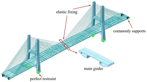
The main girder and main tower of the cable-stayed bridge are simulated by the beam element, while the stay cables are simulated by the truss element. The dimensions of these units are strictly in accordance with the actual dimensions of the cable-stayed bridge construction drawings provided. The model employs the following boundary conditions: full fixity constraints at the pylon base, compression-only elastic supports at the pylon-girder rigid connections, and elastic linkages between cables and both the girder and pylon. The simulation incorporates detailed modeling of each construction stage, including precise construction durations and the time-dependent effects of concrete shrinkage and creep. The loading scheme encompasses both permanent and variable loads, with the structural self-weight automatically calculated by the software. Additional dead loads, including beam and anchorage zone weights, are applied as either uniform or concentrated forces, while the deck pavement load is calculated at 136.4 kN/m. Vehicle loads are implemented according to Highway-I level specifications, ensuring accurate representation of operational conditions. The analysis specifically addresses the structural system transformation, distinguishing between two distinct phases: the initial cantilever cast-in-place section system prior to transformation and the subsequent semi-floating system following transformation.
4. Analysis of the influence of self-weight on cable force
The primary source of beam self-weight variations stems from concrete over-pouring during construction, a critical factor affecting both structural force distribution and geometric alignment in cantilever-built bridges, particularly when uneven over-pouring exists between opposite cantilevers. On-site measurements demonstrate that the cable-stayed bridge’s box girder sections consistently exhibit smaller cross-sectional dimensions than designed, with significant concrete accumulation in the top slab, bottom slab, and web regions, resulting in increased girder self-weight. For modeling simplification, the self-weight increase is calculated relative to the standard cross-section and can be represented as a uniformly distributed load of 42 kN/m, corresponding to a 7.1 % increase over the design self-weight value.
The self-weight augmentation induces deviations in the final bridge alignment from the intended design profile. When inadequately controlled during construction monitoring, the stress state of the cable-stayed bridge during the operation period will not be consistent with the design state. This study implements a comprehensive simulation analysis of the construction stage, incorporating a 7.1 % global overweight condition for the main beam. The resulting deformation characteristics of the main beam are presented in Fig. 4, while the corresponding cable force variations are systematically documented in Fig. 5, providing quantitative insights into the structural response to self-weight variations.
Fig. 4Variation of deflection caused by overweight of main girder
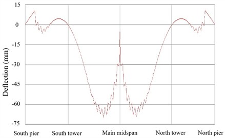
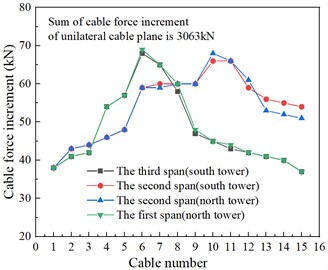
Fig. 5Cable force increment of single-side cable plane of beam body overweight 7.1 %
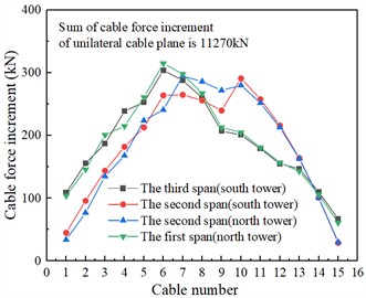
As illustrated in Fig. 4, a 7.1 % augmentation in beam self-weight induces a comprehensive downward deflection in the main span box girder, reaching a maximum deflection value of 69.8 mm. The analysis reveals that while the cast-in-place section of the side span remains relatively unaffected, other cantilever sections exhibit linear variations ranging from –6.6 mm to +4.5 mm. The increased self-weight exerts minimal influence on the side span box girder's linear configuration, whereas it significantly alters the deformation characteristics of the main span box girder. The data in Fig. 5 demonstrates that this self-weight increment results in elevated cable forces across all stay cables. And the cumulative cable force increment for both cable planes amounts to 22540 kN, constituting 34.2 % of the total measured cable force increment. This substantial percentage underscores the considerable impact of self-weight variations on the overall cable force distribution and structural behavior.
5. Analysis of the influence of prestressed tension on cable force
The primary factors contributing to prestressing tension control deviations can be categorized into two main aspects: (1) measurement inaccuracies originating from the tensioning jack's oil pressure gauge readings, and (2) various forms of prestress losses associated with construction methodologies. These prestress losses encompass multiple mechanisms, including but not limited to pipeline friction resistance variations, anchorage slip deviations, thermal effects, steel relaxation discrepancies, and creep loss deviations [9]. According to the relevant provisions of the Technical Code for Construction of Highway Bridges and Culverts (JTGT 3650-2020), considering the allowable deviation of prestress ± 10 %, it is included in the finite element model for comprehensive evaluation. The analytical results, as presented in Fig. 6, reveal that a ±10 % variation in global prestress leads to a corresponding fluctuation of 1296 kN in the cumulative cable forces across both cable planes. This variation represents merely 2.0 % of the total measured cable force increment, indicating a statistically insignificant impact. Consequently, both positive and negative prestress deviations within this range demonstrate negligible influence on the overall cable force distribution, confirming their minimal contribution to the observed structural behavior.
Fig. 6Cable force increment of prestressed tension
a) Prestress +10 %
b) Prestress –10 %
6. Analysis of the influence of the main girder alignment on the cable force
6.1. Adjustment of over-pour linear deviation
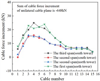
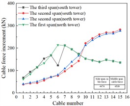
As discussed in Section 3, box girder over-pour leads to changes in the line shape of the main girder. The resulting alignment deviations can be mitigated through elevation adjustments and subsequent segment cable tensioning. In case of the actual alignment deviation remains controllable, cable force adjustments can also be implemented post-girder closure to ensure the line shape of the main girder meets design specifications. The cable force increments resulting from line shape adjustments are presented in Fig. 7. It can be seen that the linear deviation caused by the over-pour is adjusted by the cable tension, so that the main beam alignment meets the design requirements. The sum of the adjusted cable force increments on both sides of the cable plane is 6126 kN, accounting for 9.3 % of the sum of the measured cable force increments.
Fig. 7Cable force increment of linear change
6.2. Impact of the operational process
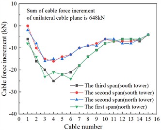
After a certain period of operation, PC cable-stayed bridges would exhibit changes in the line shape of the main beam. Factors contributing to these changes include traffic loads, temperature variations, and concrete shrinkage and creep. Typically, a pre-camber is incorporated during bridge design and construction to account for such effects. In this study, the pre-camber of the cable-stayed bridge's main girder includes deflection from 1/2 vehicle load and 10-year shrinkage and creep (104 mm in the mid-span and 14 mm in the side span). Based on this, the influence of line shape changes on cable forces during the operational stage is analyzed. Specific calculation conditions are detailed in Table 1, where the deformation in condition 3 is the deviation of the measured line shape from the designed line shape (the measured mid-span relative elevation is 36 mm lower than the design value). The corresponding cable force variations are presented in Fig. 8. The main beam exhibits a downward linear deflection, resulting in a corresponding increase in cable forces. By using the deviation between the actual and design line shape during the current operational stage as the linear variation, the cable force changes are analyzed. The total cable force increment for both cable planes is 12438 kN, representing 18.8 % of the total measured cable force increment.
Table 1Control point deformation of main girder
Condition | Deflection (unit: mm) | |
Decrement of the mid-span of the middle span girder | Decrement of the side span of the main girder | |
1 | 104 | 14 |
2 | 52 | 7 |
3 | 36 | 5 |
Fig. 8Cable force increment of unilateral cable plane
a) Condition 1
b) Condition 2
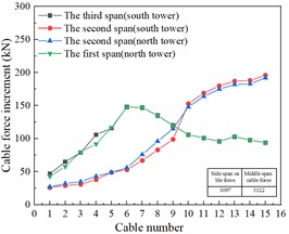
c) Condition 3
7. Conclusions
1) The increase in beam weight, prestress deviation, and main girder alignment changes have varying impacts on the cable forces of cable-stayed bridges. Among these factors, the influence of prestress tension and loss (less than 10 %) on cable forces is negligible. The effect of other factors results in a total cable force increment of 41102 kN, representing 62.3 % of the total measured cable force increment. Specifically, the increase in beam weight and main girder alignment changes contribute 34.2 % and 28.1 %, respectively.
2) The currently identified factors cannot completely explain the total observed cable force increase, especially for PC cable-stayed bridges where concrete overpour in box girders elevates both self-weight and stiffness. Self-weight calculations only consider dimensional variations within the box girder cavity. However, during concrete placement, the unformed top surface frequently causes inadequate thickness control, resulting in excessive slab thickness and beam height. These construction variations induce additional self-weight and stiffness increases beyond the design specifications.
3) Analysis reveals that beam weight increase and main beam alignment modifications contribute 62.3 % of the total cable force increment. The residual 37.7 % may be attributed to several potential factors, including: concrete shrinkage and creep effects, material property inhomogeneity, construction sequence deviations, and long-term traffic loading impacts. In the future, more relevant data should be collected in the model to expand the study of the impact of these potential factors on the cable force.
References
-
Q. Yu, Q. Sun, and J. Liu, “Friction test and parameter analysis of prestressed concrete continuous beam bridge,” Civil Engineering Journal, Vol. 32, No. 1, pp. 54–69, Apr. 2023, https://doi.org/10.14311/cej.2023.01.0005
-
X. Zhang, J. Wang, Q. Wang, M. Cao, and E. Manoach, “Service performance evaluation of long-span cable-stayed bridge based on health monitoring data,” Journal of Vibroengineering, Vol. 24, No. 4, pp. 651–665, Jun. 2022, https://doi.org/10.21595/jve.2022.22756
-
F. W. Wu and L. Zhao, “Sensitivity analysis of construction mechanical behavior parameters of long-span cable-stayed bridge,” (in Chinese), Journal of Lanzhou University of technology, Vol. 35, No. 6, pp. 124–130, 2009.
-
S. He, D. Zhou, B. Bai, C. Liu, and Y. Dong, “Experimental study on shear performance of prefabricated HSS-UHPC composite beam with perfobond strip connectors,” Engineering Structures, Vol. 324, p. 119318, Feb. 2025, https://doi.org/10.1016/j.engstruct.2024.119318
-
S. He, H. Zhong, X. Huang, Y. Xu, and A. S. Mosallam, “Experimental investigation on shear fatigue behavior of perfobond strip connectors made of high strength steel and ultra-high performance concrete,” Engineering Structures, Vol. 322, p. 119181, Jan. 2025, https://doi.org/10.1016/j.engstruct.2024.119181
-
P. Liang, “Geometric nonlinearity and stochastic simulation analysis of super-long-span cable-stayed bridge,” Tongji University, Shanghai, China, 2005.
-
Hassan, “Parametric study of cable-stayed bridges,” Journal of structural Engineering, Vol. 114, No. 8, 1988.
-
Y. J. Bao, B. S. Jiang, and W. B. Li, “Parameter sensitivity analysis of PC extradosed cable-stayed bridge in operation stage,” (in Chinese), Highway, Vol. 65, No. 8, pp. 216–222, 2020.
-
Y. J. Zhang, “Influence analysis of structural system parameters of PC girder cable-stayed bridge with double tower and double cable plane,” Zhejiang University, Zhejinag, China, 2014.
About this article

The authors have not disclosed any funding.
The datasets generated during and/or analyzed during the current study are available from the corresponding author on reasonable request.
The authors declare that they have no conflict of interest.
