Abstract
Due to the improvement of engineering material performance requirements, traditional steel anchor rods have limitations, while BFRP anchor rods have highlighted their advantages. This article focuses on the application of fully bonded BFRP anchor rods in geotechnical anchoring engineering and the construction of BFRP anchor rods. Based on the relevant roadbed slope protection anchoring projects of China Railway Eighth Bureau Group, and referring to previous experimental ideas, five sets of BFRP anchor rods with different lengths were tested for their pull-out resistance. The experimental results show that: (1) The sliding displacement of the anchor rod increases with the cyclic load, and the maximum sliding is not synchronized with the maximum load and has hysteresis and rebound. After unloading, the anchor rods with lengths of 4.8, 4.3, and 3.8 meters still have adhesive force; (2) The monitoring curve of the dynamometer is generally consistent with the design curve; (3) The key to the success of the experiment lies in the preparation of auxiliary fixtures at the loading end, the installation of strain gauges, and the waterproof treatment of wiring. This research provides a theoretical basis and reference for the optimization design and construction of BFRP anchor rods in geotechnical anchoring engineering.
1. Introduction
The expansion of transportation construction projects to mountainous areas has led to frequent disasters such as landslides and collapses. Geotechnical anchoring technology is widely used in slope protection and other engineering projects. Traditional steel reinforcement anchor rods are affected by complex geotechnical environments, and corrosion failure seriously threatens engineering safety [1, 2]. Fiber reinforced polymer (FRP) anchor rods have emerged, including BFRP, GFRP, CFRP, and AFRP. Its fiber composite structure brings good mechanical properties and corrosion resistance, lightweight and high strength, and good coordination with rock and soil deformation, which has attracted attention and research from the academic community [3].
In the research of BFRP anchor rods, on-site testing and numerical simulation are important means to analyze their pull-out performance. Looking back at the on-site pull-out test process, Wang Yang was the first to conduct relevant tests in 2017. Since then, some scholars have focused on loess strata and adopted a step-by-step loading mode to explore the reinforcement effectiveness under different anchoring parameters [4, 5]. It was found that increasing the diameter can improve the ultimate pull-out resistance, and the pull-out resistance within specific anchoring length zones increases nonlinearly and has a critical value. In the same year, Feng Jun’s team studied the influence of anchoring position and quantity on bonding performance.
However, despite significant achievements in the gradual loading mode in previous studies, there is still a lack of on-site testing of fully bonded BFRP anchor rods under cyclic loading tension, resulting in insufficient understanding of the stress-strain laws of the anchoring system under relevant working conditions [6-8]. Therefore, through on-site cyclic loading tests, the pull-out performance of fully bonded BFRP anchor rods under cyclic loading was systematically studied for the first time, revealing their mechanical behaviors such as slip displacement, load hysteresis, and bond strength after unloading, filling the gap in previous research under cyclic loading conditions. To provide theoretical basis for the optimization design and construction of geotechnical anchoring engineering, enhance engineering stability and safety, promote subsequent decision-making and technological innovation development, better meet the anchoring needs of engineering under complex geological conditions in mountainous areas, ensure engineering and surrounding ecological safety, and promote the in-depth application and technological progress of BFRP anchor rods in the field of geotechnical anchoring [9, 10].
2. Experimental design of fully bonded BFRP anchor rod under cyclic loading and drawing
2.1. Geological survey of the test area
The site pull-out test area is located near Hujiagou, Longquan Temple Town, Yongdeng County, Lanzhou City, in the DK76+0344.5-BK76+343.40 subgrade slope protection anchorage Engineering Department from Zhongchuan Airport to Wuwei section of the new railway from Lanzhou to Zhangye Third and fourth lines. The engineering geological conditions of the site are as follows: the stratigraphic lithology is dominated by the Upper Pleistocene aeolian loess of the Quaternary system (12-20 m thick, light yellow, mainly silty, slightly dense and slightly wet, Grade II common soil, 120 kPa) and the underlying Upper Neogene Upper Neogene mudstone (brown-red, mainly clay minerals, poor diagenetic and soft, grade IV soft stone, 350 kPa) [11-13]. It belongs to the Qilian uplift belt in the Qilian fold system, with stable strata, undeveloped fault structure and simple geological structure. There is no bad geology. The special soil is eolian sandy loess with self-weight collapsion (grade Ⅳ, 12-20 m thick), soft soil with slightly dense state and weak expansive mudstone. Surface water is not developed, and no groundwater is found in the depth of exploration drilling.
2.2. Test materials and equipment
The experimental materials mainly used 5 full-threaded BFRP bolts, with lengths of 2.8 m, 3.3 m, 3.8 m, 4.3 m and 4.8 m, diameters of 32 mm, densities of 2.05 g/cm³, tensile strength of 834 MPa, elastic modulus of 45 GPa, elongation at break of 1.89 % and shear strength of 255 MPa.
The test equipment includes multiple systems such as hole forming, grouting, loading, monitoring and laptop computers, as shown in Fig. 1. The pneumatic anchor drill is selected for drilling, and the compressed air is used as the power to ensure the drilling accuracy and efficiency. The loading system is based on a manual oil compression core jack with a rated tonnage of 65 tons and a stroke of 18 cm. It operates in cooperation with ZB4-500 electric oil pump, Φ50 and Φ32 anchors, reaction pier and steel cushion plate [14-15]. A dial indicator with a range of 50 mm and an accuracy of 0.01 mm for displacement monitoring; Drawing load is collected by Changzhou Jinmu 100Φ80 vibrating string anchor cable dynamometer (JTM-V1800) and supporting YT-RG-01 reading meter; The strain acquisition relies on DH3816N static strain test system and BX120-20AA resistance strain gauge to meet the needs of complex conditions and multiple measuring points.
2.3. Test scheme design
2.3.1. Prepare the anchor bolt
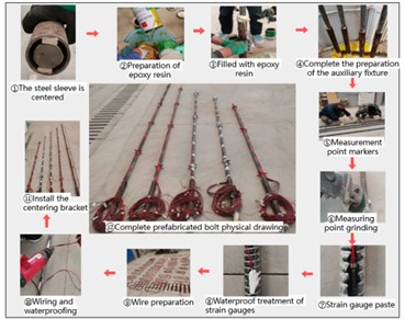
This test takes BFRP anchor rod as the key object. After selecting different lengths of bolt according to the test design, prepare bolt according to the following steps: First, the steel sleeve with a length of 0.8 m, an outer diameter of 50 mm and a wall thickness of 5 mm was centralized and filled with 1:1 epoxy resin and curing agent with filling agent. Then, auxiliary fixtures were prepared, the measuring points were marked and sanded, strain gauges were affixed, and the strain gauges were waterproof with latex coating. An 8-meter wire was prepared, the DH3816N static strain test system was connected and waterproof treatment was done, and the centring bracket was installed. The production process is illustrated in Fig. 2.
Fig. 1Field drawing test system
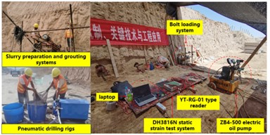
Fig. 2Bolt preparation flow chart
2.3.2. Preparatory test
Before the formal test, a pneumatic drill was used to drill holes on the same slope, with horizontal spacing ≥ 1 m, diameter 110 mm, Angle of 15° from the horizontal, and depth exceeding the corresponding anchor length of 0.5 m. One hole ≥ 3.3 m, 3.8 m, 4.3 m, 4.8 m, 5.3 m was drilled successively. The anchor rod with the strain gauge attached and the center support installed was placed into the borehole manually, and grouting was performed with the standard 42.5R cement and 0.45-0.5 water-cement ratio pure cement slurry by the method of regrouting at the bottom of the hole. After grouting from the bottom of the hole to the hole, the pipe was pumped. When the slurry was initially set, the leakage and grouting were checked to ensure that the anchoring section was filled, and the maintenance period exceeded 28 days to meet the subsequent test requirements. The drawing load is designed to take the ultimate bond strength 40 kPa according to the plastic state of the viscous soil. The ultimate failure load of each anchorage length is calculated by using the relevant formula (0.11 m, takes different values) (see Table 1) to guide the setting of test loading parameters.
After the back calculation of the ultimate failure load is completed, the cyclic load scheme is carried out.
Table 1Predicted ultimate failure load of bolt drawing at different anchoring lengths
Length of anchorage section (m) | 4 | 3.5 | 3 | 2.5 | 2 |
Estimated ultimate failure load (KN) | 55.26 | 48.45 | 41.45 | 34.54 | 27.63 |
2.3.3. Loading test
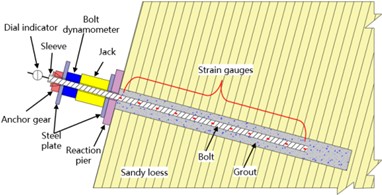
After leveling the drilling slope, the reaction pier, steel backing plate 1, core jack, anchor cable dynamometer, steel backing plate 2, anchor, fixture and dial indicator are installed in sequence. The dial indicator is fixed on the self-made scaffold by magnetic base. The device schematic diagram is shown in Fig. 3.
This BFRP anchor pulling test followed relevant specifications, adopted cyclic loading, and controlled loading and unloading load and speed by manual oil pressure gauge (adding 0.07 MPa/s and unloading 0.14 MPa/s). The load is divided into multiple cycles. After the initial load is stabilized for more than 1 minute and the first cycle load is stabilized for more than 10 minutes, the load is unloaded back to the initial load for more than 1 minute. Then load step by step, stabilize the pressure, unload back to the initial load. The test shall be terminated until the anchoring system is damaged or the judgment condition is reached. If the criterion is not met, the test shall be continued on the basis of the maximum failure load multiplied by 1.2 times and 1.5 times respectively. Failure judgment basis: the end displacement of bolt is not convergent, the anchor solid is pulled out or the bolt is pulled out; The displacement increment of the load in the latter stage exceeds that of the upper stage by 2 times.
Fig. 3Schematic diagram of BFRP bolt drawing test device
3. Experimental result
3.1. Failure mode analysis of BFRP anchoring system
This experiment explores the failure form and mechanism of BFRP anchor system under cyclic pulling load, and its apparent changes are observed and recorded during the whole process of pulling test. The initial load is small and the response of the anchoring system is weak. The “squeaking” sound comes out when the load increases, which is inferred that the interface between bolt and slurry is subjected to shearing stress. With the change of load and holding load, the five groups of anchors appear the second interface failure, accompanied by local soil collapse at the hole, mud expansion near the anchor hole and inclusion crushing and slip-off, etc. In the test, the anchorage system is mainly the second interface sliding failure.
3.2. Analysis of the relationship between cyclic load and displacement of BFRP anchor
The displacement curve of BFRP anchor rod under cyclic load presents two significant features: First, the slip displacement of each anchor rod gradually increases with the increase of cyclic load, and the displacement increment of the latter cycle is larger than that of the previous cycle, and the increment difference of the first two cycles near failure is particularly prominent; Second, the maximum slip displacement point of most bolts (4.8 m, 4.3 m, 3.8 m) lags behind the maximum cyclic load point. In the early stage of unloading, the bolts still slip out due to large residual load, and the displacement rebound occurs at low load, indicating that the bonding force still exists after unloading. Although the displacements of the 3.3 m and 2.8 m bolts are not synchronized with the maximum cyclic load, their displacements continue to increase from unloading to the end, and show a linear and rapid growth trend after the maximum cyclic load.
3.3. Comparative analysis of bolt dynamometer load and design cyclic load
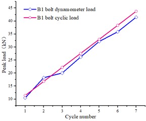
In this test, the design cyclic load is applied to BFRP bolt by jacks, and the feasibility of the operation scheme is verified by the monitoring data of the connected bolt dynamometer. The B1 bolt is taken as an example. As can be seen from Fig. 4, the monitoring load is positively correlated with the phased changes of the design cycle load, but due to uncertainties in practical operation, the monitoring load is difficult to match the theoretical value. However, the time-history curves of the two are consistent and the values are similar, indicating that the experimental operation is highly feasible. Looking at Fig. 5, except for the slightly larger peak load of the bolt dynamometer in the second cycle, the rest are small, indicating that there is a stress loss in the force transmission, but the overall two are close, indicating that the test effect is good and the operation plan is feasible.
Fig. 4Comparison of time history curve between monitoring load and design cyclic load by bolt dynamometer
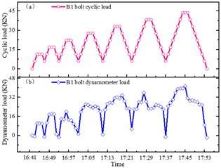
Fig. 5Comparison of peak curve of bolt dynamometer and design cyclic load
4. Conclusions
This article focuses on BFRP bolt field testing, covering scheme design, preparation, testing process and results. The pull-out test showed that the anchor solids were mostly second-interface pull-out failures. Main conclusions: During cyclic loading, the slip displacement of the bolt increases with the load, the increment of the latter cycle is greater than that of the previous cycle, the difference between the increments of the first two cycles is obvious when the failure is approaching, the maximum slip displacement point lags behind the maximum cyclic load point, and some of the bolts have displacement rebound during unloading, which reflects the characteristics of the anchoring system. The time history curve of the load monitored by the dynamometer is consistent with the design load curve, but the peak value is small, and there is stress loss due to the force transmission of the jack, but the overall test effect is good. In the operation of BFRP bolts, the preparation of auxiliary fixtures at the loading end should ensure the bonding strength and concentricity of the steel sleeve and the anchor, the strain gauge should be posted and wired to do a good job of waterproofing, and the follow-up research should pay attention to the protection of the orifice wire to prevent the distortion of strain data and the damage of the wire.
References
-
L. Tang, H.-G. Wu, H. Wei, K. Feng, and G.-J. Reng, “Application of a new basalt fiber-reinforced polymer anchorage structure in the tunnel-slope system under rainfall action,” Journal of Mountain Science, Vol. 20, No. 2, pp. 570–584, Feb. 2023, https://doi.org/10.1007/s11629-022-7483-6
-
N. K. Alotaibi, “Evaluating the impact of different anchor configurations and patch arrangements on the performance of fiber-reinforced polymer (FRP) anchors,” Construction and Building Materials, Vol. 415, p. 135110, Feb. 2024, https://doi.org/10.1016/j.conbuildmat.2024.135110
-
G. X. Chen, “Research on tensile hardening effect of concrete members with FRP bars,” Hainan University, 2022.
-
M. He, S. Ren, H. Xu, S. Luo, Z. Tao, and C. Zhu, “Experimental study on the shear performance of quasi-NPR steel bolted rock joints,” Journal of Rock Mechanics and Geotechnical Engineering, Vol. 15, No. 2, pp. 350–362, Feb. 2023, https://doi.org/10.1016/j.jrmge.2022.03.011
-
J. T. Jiang and Y. Gao, “Review on the shear performance of concrete beams with FRP bars,” (in Chinese), Composite Materials Science and Engineering, No. 12, pp. 119–128, 2023, https://doi.org/10.19936/j.cnki.2096-8000.20231228.016
-
C. Zhu et al., “Volumetric deformation and damage evolution of Tibet interbedded skarn under multistage constant-amplitude-cyclic loading,” International Journal of Rock Mechanics and Mining Sciences, Vol. 152, p. 105066, Apr. 2022, https://doi.org/10.1016/j.ijrmms.2022.105066
-
B. Song, L. Jin, and X. L. Du, “Experimental study on shear performance and bearing capacity calculation of concrete short beams with FRP bars,” Journal of Southeast University (Natural Science Edition), Vol. 3, No. 10, pp. 102–103, Jan. 2022, https://doi.org/10.37155/2717-5316-0310-36
-
D. H. Liu, Y. H. Chen, F. Xu, Z. Z. Shao, and J. J. Yang, “Research progress of basalt fiber composite bolt for geotechnical engineering,” (in Chinese), Synthetic fibers, No. 9, pp. 83–86, 2023, https://doi.org/10.16090/j.cnki.hcxw.2023.09.001
-
W. Z. Mao, “Design and performance evaluation of prestressed BFRP anchor rods,” (in Chenese), Southeast University, 2023.
-
J. Q. Zhang, “Monitoring and identification of loose zone of tunnel surrounding rock based on Self-sensing FRP anchor rod,” (in Chenese), Harbin Institute of Technology, 2023.
-
G. Muciaccia, M. Khorasani, and D. Mostofinejad, “Effect of different parameters on the performance of FRP anchors in combination with EBR-FRP strengthening systems: A review,” Construction and Building Materials, Vol. 354, p. 129181, Nov. 2022, https://doi.org/10.1016/j.conbuildmat.2022.129181
-
B. Grindheim, N. Trinh, C. C. Li, and A. H. Høien, “Investigating load arches and the uplift capacity of rock anchors: a numerical approach,” Rock Mechanics and Rock Engineering, Vol. 57, No. 9, pp. 7313–7342, May 2024, https://doi.org/10.1007/s00603-024-03930-6
-
J. Liu, R. Q. Sun, Y. Zhang, R. Song, H. Wang, and T. Sun, “Study on expansion and drawing test of self-expanding anchor in anisotropic initial geostress soft rock,” Journal of coal, Vol. 47, No. 10, pp. 3634–3644, 2022, https://doi.org/10.13225/j.carolcarrollnki jccs.2021.1622
-
W. H. Zha, J. J. Wang, X. Z. Hua, Z. B. Liu, and C. H. Wang, “Research review on anchoring performance and interface mechanical properties of anchor bolt,” Yangtze River of the People, Vol. 52, No. 11, pp. 161–168, 2021, https://doi.org/10.16232/j.cnki.1001-4179.2021.11.027
-
J. Feng, Y. Wang, Y. F. Zhang, L. Huang, C. J. He, and H. G. Wu, “Field comparative test study on anchoring performance of basalt fiber and reinforced anchor rod,” Rock and Soil Mechanics, Vol. 40, No. 11, pp. 4185–4193, 2019, https://doi.org/10.16285/j.r.2018.1640
About this article

The authors have not disclosed any funding.
The datasets generated during and/or analyzed during the current study are available from the corresponding author on reasonable request.
The authors declare that they have no conflict of interest.
