Abstract
Modal characteristics serve as a critical basis for evaluating the vibration and noise performance of automotive brakes. Using the finite element software ABAQUS, modal simulations were performed on the assembly comprising brake disc, brake pad, piston, caliper, and retainer, calculating the modal shapes and frequencies within the specified range. Modal parameters of each component within this range were obtained through measurements using a Doppler laser vibrometer and an NI data acquisition system, as well as hammering tests. By comparing the experimental and simulation results, it was found that the errors for all components were within 5 %, meeting the accuracy requirements. This validation confirms the accuracy of the structural and material parameters of each brake component. The results demonstrate that this type of brake is less susceptible to low-frequency resonance, as the first-order natural frequencies of both the brake disc and the brake pad exceed 1 kHz.
Highlights
- Using the finite element software ABAQUS, modal simulations were performed on the assembly comprising brake disc, brake pad, piston, caliper, and retainer, calculating the modal shapes and frequencies within the specified range.
- Modal parameters of each component within this range were obtained through measurements using a Doppler laser vibrometer and an NI data acquisition system, as well as hammering tests.
- Bycomparing the experimental and simulation results, it was found that the errors for all componentswere within 5 %, meeting the accuracy requirements.
1. Introduction
The vibration and noise caused by brakes can be categorized into three types based on frequency range: brake judder, brake flutter, and brake squeal. Brake judder typically occurs within the frequency range of 0 to 100 Hz and is primarily attributed to fluctuations in braking torque, braking pressure, and brake disc thickness during vehicle deceleration [1, 2]. Brake flutter generally falls within the frequency range of 0 to 500 Hz, with noise in this range manifesting at the onset of braking. This phenomenon is mainly associated with stick-slip vibrations, which are commonly observed during vehicle startup and low-speed driving [3]. When the frequency exceeds 1 kHz, the resulting noise is classified as brake squeal. This type of noise can occur under various vehicle operating conditions and exhibits variability and randomness [4]. The primary methods for studying brake noise can be categorized into two main types: numerical analysis methods and experimental testing methods. In the early stages of brake noise research, due to the limited availability of computer technology and insufficient computational power, experimental methods were predominantly used [5]. However, experimental methods also had certain drawbacks, as they were easily influenced by environmental and human factors, which could lead to errors in experimental results during the study of brake noise issues [6, 7]. With technological advancements, computer science has also undergone significant development, and the computational power of computers has been greatly improved [2]. As a result, increasingly sophisticated numerical analysis methods have been widely used by many researchers. Each component of the automotive braking system has its own fixed properties, which can be described by mode shape, natural frequency, and damping ratio. Therefore, modal analysis of each component of the braking system is required to obtain the mode shape and natural frequency of the components. The mode shape and natural frequency of the components are also the basis for analyzing the generation of brake noise.
2. Structure and composition of disc brake
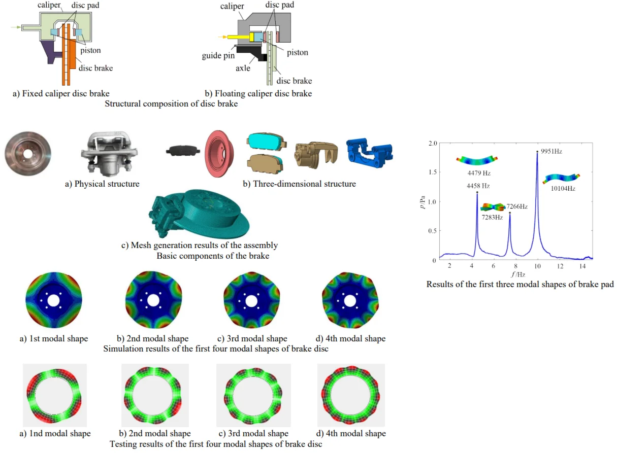
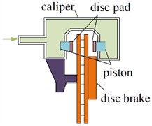
2.1. Structural and working principle
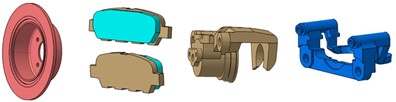
Based on the structural differences and the motion state of the caliper, disc brakes can be classified into fixed caliper disc brakes and floating caliper disc brakes, as shown in Fig. 1. Both types comprise brake pads, brake discs, and a hydraulic system. The hydraulic system supplies the pressure required to actuate the pistons within the braking system. Brake pads consist of a metal backing plate and friction material, mounted on both the inner and outer sides of the brake disc. The brake disc is attached to the wheel hub and rotates with it. For fixed caliper disc brakes, when the driver depresses the brake pedal, the master cylinder transfers hydraulic pressure through the fluid lines to the pistons. This causes the pistons on both sides of the caliper to extend outward, pressing the brake pads against the brake disc, thereby generating sufficient friction to counteract the rotational torque of the wheel, resulting in vehicle deceleration or stopping. For floating caliper disc brakes, the caliper body is designed to slide along guide pins. When the brake pedal is depressed, hydraulic fluid enters the caliper, pushing the inner piston and brake pad against the brake disc. Simultaneously, this movement also causes the caliper body to slide inward, bringing the outer brake pad into contact with the opposite side of the brake disc. This ensures that both brake pads press firmly against the brake disc for effective braking. Upon releasing the brake pedal, the sealing ring and clamp spring return the caliper body, pistons, and brake pads to their original positions. Therefore, the floating caliper disc structure can adapt to more complex working conditions and provide better linearity in braking force.
Fig. 1Structural composition of disc brake
a) Fixed caliper disc brake
b) Floating caliper disc brake
2.2. Classification of vibration and noise
Braking noise is generated due to the vibration between the brake disc and other components during the braking process. The frequency distribution range of braking noise is very wide, ranging from tens of Hertz to hundreds of thousands of Hertz, but the frequency range that is acceptable to the human ear is generally around 20-16000 Hz. Braking noise is now mainly classified according to the frequency, which can be roughly divided into the following three categories: low-frequency noise (below 1000 Hz), low-frequency howl (1000 Hz-3000 Hz), and high-frequency howl (3000 Hz-16000 Hz). Lang summarized various NVH issues related to braking and defined them using onomatopoeia, including judder, groan, moan, howl, squeal, squeak, and wire-brush.
Low-frequency noise generally includes sounds such as judder and moan. It primarily occurs during low-speed braking and reverse braking. Factors that affect this noise mainly include brake disc thickness, brake pad friction material, steering knuckle, suspension, and other factors. The main reason for low-frequency squeal is the coupling phenomenon of the first few modal frequencies of various components, which leads to vibration and instability in the braking system. Among the numerous influencing factors, the friction coefficient between the disc and the pad, as well as the stiffness of contact during friction, are two factors that have a significant impact on high-frequency squeal. High-frequency squeal generally has a higher sound pressure level, posing greater harm to the health of drivers and passengers. Therefore, high-frequency squeal is the focus of research on brake noise. In practical engineering applications, there are generally two methods to calculate the modal parameters of components: one is through finite element method calculations, known as computational modal analysis; the other is by utilizing specialized testing equipment such as sound pressure sensors, acceleration sensors, and force hammers, known as experimental modal analysis.
3. Modal simulation and analysis
3.1. Modeling for modal calculation
From the perspective of computational solving methods, modal analysis involves solving the coordinates of the linear system’s ordinary differential equations and the motion equations when coupling occurs. By solving these equations, we obtain eigenvalues and characteristic equations. Subsequently, decoupling these equations allows us to acquire the modal parameters of the system equations. Mathematically, it involves solving for the eigenvalues of the system equations and the modal parameters within the matrix equation system. The solved eigenvalues represent the natural vibration frequencies of the system, while the solved vectors can represent the vibration modes of the system. Compared to drum brakes, disc brakes have fewer tiny components. However, it still needs to be noted that when establishing a brake noise analysis model, simplification of some features of the components themselves is still required. To ensure the accuracy of the model analysis results, the following simplifications are made in the established finite element model:
(1) Ignore features such as numbers, marks, and symbols on the surface of the component.
(2) Ignore features such as chamfers and protrusions on the upper part of the component, but strive to maintain the main features of the component.
(3) Ignore the alarm and clamp spring components on the brake pad backing plate.
(4) Neglect the sealing rings and dust masks between the piston and the caliper body, as well as between the cage and the guide pin.
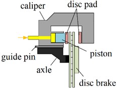
Fig. 2Basic components of the brake
a) Physical structure
b) Three-dimensional structure
c) Mesh generation results of the assembly
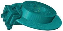
The physical structure of the disc brake is shown in Fig. 2(a), and its simplified three-dimensional model is shown in Fig. 2(b). Using the software ABAQUS for mesh generation, different mesh sizes were employed for the analysis when partitioning the finite element network model. On the premise of ensuring accurate analysis results, a mesh density of 2-3 mm was predominantly used for partitioning. Increasing mesh precision beyond this range did not significantly affect the accuracy of the results but instead increased the time cost of the analysis. The model mesh partitioning primarily relied on hexahedral quadratic reduced elements (C3D20R). The brake disc, brake pad, back plate, and piston, which are the main components affecting the vibration and noise generated by the braking system, were partitioned using fully hexahedral elements. Compared to the complex structure of the caliper body, retainer, and guide pin, optimized tetrahedral elements (C3D10) were used for mesh partitioning of these components. The overall mesh-partitioned disc brake analysis model is shown in Fig. 2(c).
3.2. Analysis and verification of modal characteristics
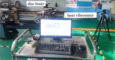
In most modal test analyses, the most commonly used testing method is the hammering test method. For all measurement techniques, input and output signals need to be sampled to digitize the time-domain data. In experimental modal analysis, to detect the vibration response of the structure, an external force is applied as an excitation. This excitation method can generally be divided into hammering excitation and vibrator excitation. Because the equipment used in hammering excitation is relatively convenient and simple, the hammering test method is adopted to extract the modal parameters of the structure. The experimental equipment for hammering method modal testing includes multiple components such as a force hammer, a data acquisition system, and a microphone. The force hammer is used to strike the tested component to obtain excitation, and the data acquisition system can extract parameters such as the natural frequency and mode shape of the tested component. To excite each order frequency of the component, a force hammer with a relatively hard hammerhead is used in this paper to apply excitation to the component. In order to excite each order frequency of the component, this paper uses a force hammer with a relatively hard hammer head to excite the brake pad component, as shown in Fig. 3. Laser vibrometer is an optical instrument that employs laser measurement technology for non-contact testing of the dynamic characteristics of components. This device has specific requirements for the reflective properties of the measured object to ensure accurate reception of laser signals. While it can precisely measure out-of-plane vibration characteristics, its accuracy for in-plane vibration characteristics of general structures is relatively lower. Given the reflective properties of brake discs and their abundance of out-of-plane modes, a Doppler laser vibrometer is suitable for measuring the modal vibrations of brake discs, as illustrated in Fig. 4.
Fig. 3Modal testing instrument for brake pad
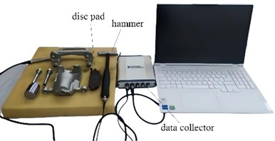
Fig. 4Modal testing instrument for brake disc
In the modal test of the laser vibrometer, the constrained mode is adopted, and no load needs to be applied to the brake disc. Therefore, the constrained mode calculation of the brake disc is completed by using the finite element software ABAQUS. Since the in-plane mode and the nodal diameter mode of the brake disc are not easy to be excited by the force hammer, the results of the first seven nodal diameter modes of the structure are extracted and compared with the test results. The natural frequencies of the first seven nodal diameter modes of the brake disc are shown in Tab.1. The errors of each order frequency are all within 5 %, meeting the accuracy requirements.
Table 1Test and calculation results of natural frequencies
Order | 1 | 2 | 3 | 4 | 5 | 6 |
Test value of natural frequency / Hz | 1074 | 1571 | 2213 | 3084 | 4159 | 5563 |
Simulation value of natural frequency / Hz | 1020 | 1513 | 2224 | 3175 | 4342 | 5702 |
Relative error / % | 5.0 | 3.7 | 0.5 | 3.0 | 4.4 | 2.5 |
The out-of-plane modal shapes of the first four orders of the brake disc were measured by a laser vibrometer. The comparison charts of the out-of-plane modal shapes obtained from the finite element analysis and those measured by the laser vibrometer are shown in Fig. 5 and Fig. 6. The results of modal analysis of the brake disc show that the brake disc shows a series of unique vibration modes in a specific frequency range. These modes include not only the common bending vibration, but also torsional vibration, axial vibration and other forms. Through the detailed finite element analysis, it can be found that the low order mode is mainly manifested in the overall bending vibration, which usually occurs at a lower frequency, and has a significant impact on the overall stiffness and stability of the brake disc. The higher-order modes show more complex deformation characteristics, such as local torsion and subtle surface vibration. These higher-order modes are often excited at higher frequencies, which puts forward higher requirements for noise and vibration control in the braking process.
Fig. 5Simulation results of the first four modal shapes of brake disc
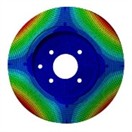
a) 1st modal shape
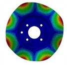
b) 2nd modal shape
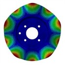
c) 3rd modal shape
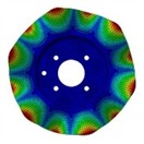
d) 4th modal shape
Fig. 6Testing results of the first four modal shapes of brake disc
a) 1nd modal shape
b) 2nd modal shape
c) 3rd modal shape
d) 4th modal shape
To verify and accurately extract the natural frequency of the brake pad, the brake pad is placed on a softer sponge. Conduct single-point hammering test on brake pad by force hammer, and extract test modal parameters by single-point excitation method. Excitation signal and response signal are processed and analyzed by NI data acquisition system and LABVIEW software. The modal analysis results of the brake pad show that the brake pad has different vibration modes under different frequencies. Generally, lower order modes include bending and torsional vibrations, while higher order modes involve more complex deformations. The analysis results are helpful to understand the dynamic response of brake pad in actual work, so as to optimize its design, reduce noise and vibration, and improve braking performance and durability.
Fig. 7Results of the first three modal shapes of brake pad
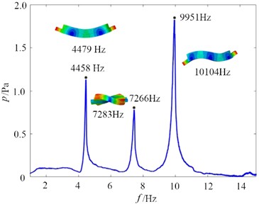
The modal analysis results of the brake pad are shown in Fig. 7. It can be seen that the brake pad has different vibration modes under different frequencies. Generally, lower order modes include bending and torsional vibrations, while higher order modes involve more complex deformations. The analysis results are helpful to understand the dynamic response of brake pad in actual work, so as to optimize its design, reduce noise and vibration, and improve braking performance and durability. The natural frequencies of the brake system are closely correlated with the noise frequencies it generates. When the excitation frequencies during braking (such as variations in brake disc rotational speed or friction-induced frequencies) approach or coincide with one of the brake’s modal frequencies, resonance occurs. In this resonant state, the vibration amplitude increases dramatically, leading to a significant rise in noise intensity. The noise frequency spectrum often clusters around the modal frequencies. Therefore, understanding the modal frequencies of the brake is essential for predicting and mitigating noise generation.
4. Conclusions
This paper performs a modal analysis on the assembly of disc brakes, focusing on the system’s vibration response. Under different excitation frequencies, the dynamic responses of various brake components exhibit significant variations. While the amplitudes of the mode shapes differ, the trends in modal changes remain consistent. For the same mode order but different natural frequencies, the tendencies of torsion, deformation, and bending are similar, but their extents vary. Since the shape and structure of the brake disc remain constant in the analysis, the deformation of the brake disc at the same mode order but different frequencies is essentially identical. Different shapes and structures influence the modal shapes and natural frequencies. Based on the connection between the modal and acoustic properties of the brake, noise can be reduced by optimizing the brake structure. For instance, by adjusting the thickness and material of the brake disc to change its modal frequency, it can be made to avoid the common excitation frequency range as much as possible, thereby reducing the possibility of resonance.
References
-
M. H. C. Maciel, R. D. N. Rodrigues, C. A. S. Costa, R. A. Bezerra, V. V. Gonçalves, and T. V. A. de Freitas, “Brake squeal finite element performance comparison between commercial and coconut shell-reinforced material drum brake linings,” Proceedings of the Institution of Mechanical Engineers, Part L: Journal of Materials: Design and Applications, Vol. 239, No. 1, pp. 100–110, Apr. 2024, https://doi.org/10.1177/14644207241247741
-
D. Zhu et al., “Noise and vibration performance of automotive disk brakes with laser-machined M-shaped grooves,” Proceedings of the Institution of Mechanical Engineers, Part D: Journal of Automobile Engineering, Vol. 237, No. 5, pp. 978–990, Apr. 2022, https://doi.org/10.1177/09544070221085972
-
L. Yang, H. Zhang, P. Zhao, Z. Wang, C. Zhao, and J. Mo, “Dynamic characteristics of disc brake systems of a high-speed train with wheel polygonal wear,” Proceedings of the Institution of Mechanical Engineers, Part F: Journal of Rail and Rapid Transit, Vol. 238, No. 9, pp. 1151–1166, Jun. 2024, https://doi.org/10.1177/09544097241264322
-
S. Gaygol and K. Wani, “Modal analysis of plate to analyze the effect of mass stiffeners using the Chladni plate approach,” Materials Today: Proceedings, Vol. 72, No. 3, pp. 1314–1321, Jan. 2023, https://doi.org/10.1016/j.matpr.2022.09.305
-
X. Li, D. Zhao, H. Zhai, M. Chen, and T. Zhang, “Modal analysis of circular arches in rectangular coordinate system,” Structures, Vol. 47, No. 1, pp. 2129–2137, Jan. 2023, https://doi.org/10.1016/j.istruc.2022.12.036
-
R. D. Nascimento Rodrigues et al., “Analysis of geometric and material parameters in the modal stability of wind turbine brakes using the complex eigenvalue method,” Noise and Vibration Worldwide, Vol. 55, No. 8, pp. 438–453, Aug. 2024, https://doi.org/10.1177/09574565241270210
-
M. Yang, W. Jiang, J. Bao, and C. Zhang, “Complex modal optimization of the disk brake based on thermal-structural coupling,” Mechanics Based Design of Structures and Machines, Vol. 52, No. 12, pp. 10422–10438, Dec. 2024, https://doi.org/10.1080/15397734.2024.2356064
About this article

The authors have not disclosed any funding.
The datasets generated during and/or analyzed during the current study are available from the corresponding author on reasonable request.
The authors declare that they have no conflict of interest.
