Abstract
Modal characteristics are critical indicators for assessing the stability of harmonic reducer and serve as an essential basis for structural optimization. Based on the structure and working principle, the finite element model of harmonic reducer was systematically established and appropriately simplified. According to Block Lanczos method, the natural frequencies and mode shapes of the flexible gear and rigid gear under free boundary conditions were obtained by ANSYS. The single-factor analysis method was employed to investigate the influence of structural parameters of the flexible gear on its natural frequency and torsional stiffness. Results indicate that the natural frequency of the flexible gear increases with the length and wall thickness of the cylindrical section. Although the natural frequency of the flexible gear is lower than that of the rigid gear, it remains higher than the working excitation frequency, thus avoiding resonance. Additionally, the maximum stress in the flexible gear decreases with increasing tube length and wall thickness, which contrasts with the trend observed for torsional stiffness.
Highlights
- Based on the structure and working principle, the finite element model of harmonic reducer was systematically established and appropriately simplified.
- According to Block Lanczos method, the natural frequencies and mode shapes of the flexible gear and rigid gear under free boundary conditions were obtained by ANSYS.
- The single-factor analysis method was employed to investigate the influence of structural parameters of the flexible gear on its natural frequency and torsional stiffness.
1. Introduction
The harmonic drive reducer, also called harmonic reducer or harmonic gear reducer, is widely used in the aviation field, mainly used in aircraft control, satellite deployment system, space probe, landing gear system, engine control system and experimental equipment [1, 2]. The harmonic drive reducer is composed of fixed inner teeth rigid wheel, flexible wheel and wave generator that causes radial deformation of flexible wheel. The harmonic reducer is a new transmission structure in the gear reducer. It uses the flexible gear to generate controllable elastic deformation wave, and causes the relative staggered teeth between the rigid wheel and the flexible wheel to transmit the power and motion. This kind of transmission is essentially different from the general gear transmission, and has particularity in meshing theory, set calculation and structural design [3]. The harmonic gear reducer has the advantages of high precision and high bearing capacity. Compared with the common reducer, the material used is 50 % less, and its volume and weight are reduced by at least 1/3. Harmonic gear reducers are increasingly widely used in aerospace, energy, machine tools, transportation, medical devices and other aspects, especially in the servo system with high dynamic performance. Harmonic gear drive shows its superiority. It is very necessary to analyze the dynamic characteristics of harmonic reduction gear, which is also one of the key factors directly affecting the performance of the entire transmission system [4]. Dynamic characteristics analysis is helpful to understand the response characteristics of harmonic reduction gear in actual work, including its vibration, impact and noise, etc. [5, 6]. This is essential to improve the stability and reliability of the drive train. By analyzing the load response characteristics of harmonic reduction gear, its performance under different working conditions can be predicted and evaluated, so as to provide basis for design optimization. Modal analysis can help identify and solve problems that may occur during operation of harmonic reduction gears, such as resonance and fatigue failure, so as to extend their service life [7]. Dynamic characteristics analysis of harmonic reduction gears is a key step to ensure high performance, high reliability and long service life.
2. Structure and operating principle of harmonic reducer
2.1. Structural composition
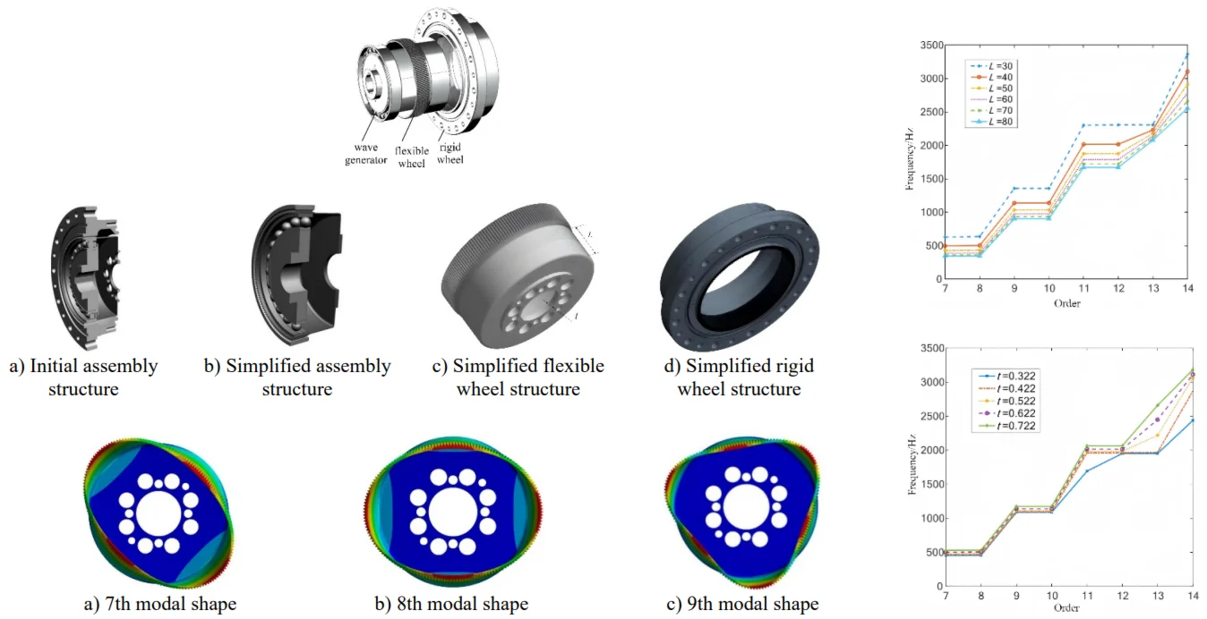
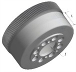
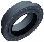
The harmonic reducer is mainly composed of components such as wave generator, flexible wheel, rigid wheel, and bearings, as shown in Fig. 1. The wave generator is usually composed of an eccentric shaft and ball bearings. The flexible wheel and the rigid wheel have internal and external teeth respectively, and the meshing with the rigid wheel is achieved through the elastic deformation of the flexible wheel. Flexible wheel belongs to elastic thin shell components, mainly divided into structural types such as cylindrical, top hat, and circular. The rigid wheel is usually designed as a component with high stiffness, and wave generators are generally divided into structural types such as roller type, eccentric disc type, and cam type. The cam type wave generator is widely used and generally consists of a cam and thin-walled bearings.
Fig. 1Structural composition of medical grinding machine
2.2. Working principle
During the rotation of the wave generator, the flexible wheel undergoes periodic elastic deformation through eccentric action, forming an elliptical internal tooth profile. As the wave generator rotates, the meshing point between the flexible teeth and the rigid teeth constantly changes, thereby achieving deceleration transmission. During the rotation of the wave generator, the flexible wheel undergoes periodic elastic deformation through eccentric action, forming an elliptical internal tooth profile. As the wave generator rotates, the meshing point between the flexible teeth and the rigid teeth constantly changes, thereby achieving deceleration transmission. Due to the fact that harmonic reducers consist of three basic transmission components, when different components are used as inputs and outputs, harmonic reducers can form four forms: acceleration, deceleration, differential, and approximately constant speed. Considering the complexity and service life of the structure, the main types currently used are dual wave harmonic reducers and triple wave harmonic reducers. The wave generator of the double wave harmonic reducer is generally elliptical cam shaped, with a meshing area of two parts symmetrically distributed, but its ability to withstand impact is poor. The teeth of the flexible wheel at the short axis position completely disengage from the teeth of the rigid wheel, forming a disengagement area, while the contact between the long and short axes is a transitional state from engagement to disengagement.
3. Simulation and analysis of modal characteristics
3.1. Establishment of finite element model
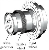
The reducer is composed of several key parts such as flexible wheel, rigid wheel and wave generator. The fine size characteristics of the parts have a great impact on the accuracy and calculation quantity of finite element analysis. Therefore, the harmonic reducer shall be reasonably simplified, as shown in Fig. 2.
(1) In actual use, the harmonic reducer is connected to the output end through the bolt hole at the bottom of the cylinder for power transmission. Due to its relatively high thickness and rigidity, the circular hole feature at this position can be ignored in the actual design process. At the same time, there are two chamfers at the gear ring of the flexible gear, including the front chamfer of the gear ring and the transition bevel between the gear ring and the cylinder. This feature will affect the mesh area between the flexible wheel and the rigid wheel, and also affect the stiffness of the flexible wheel at the gear ring position. Therefore, this paper retains the chamfer feature of this position, so as to ensure the accuracy of the contact state and the stiffness.
(2) The wave generator consists of a bearing and a cam. The bearing is installed on the cam. Considering that the retainer in the thin-walled bearing is basically not stressed and is not an important analysis object, the retainer is omitted.
(3) The installation flange is omitted and only the complete gear ring structure is retained. At the same time, the front end and rear end of the gear ring of the rigid wheel are designed with gear ring chamfer, which will affect the mesh area of the flexible wheel and the rigid wheel, so the structure is retained.
Fig. 2Simplification of finite element model
a) Initial assembly structure
b) Simplified assembly structure
c) Simplified flexible wheel structure
d) Simplified rigid wheel structure
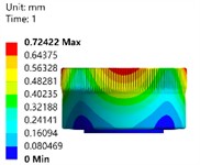
To verify the error of the simplified FEA model, a three-dimensional optical deformation measurement and analysis system was used, as shown in Fig. 3(a). By continuously photographing the surface of the object under test with a high-resolution camera and compensating for the optical distortion of the measurement lens, the deformation of the flexible wheel structure could be obtained. The testing sample was placed in a tensile testing machine, as shown in Fig. 3(b), and a compressive load of 50 N was applied. The final deformation response result is shown in Fig. 3(c). Meanwhile, under the same load and constraint conditions, static strength simulation was performed on the simplified model, and the steady-state deformation was calculated as shown in Fig. 3(d). The results show that the deformation deviation of the simplified finite element model under static calculation conditions is only 3.6 %. This can prove that this FEA model can effectively ensure the accuracy for modal analysis.
Fig. 3Error verification for the simplified model

a) Deformation testing system
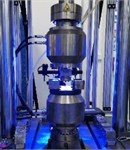
b) Component loading
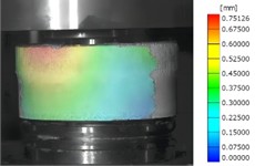
c) Deformation test result
d) Deformation simulation result
3.2. Modal analysis of flexible wheel and rigid wheel
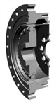
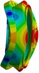
The extraction methods of modal path usually include Block Lanczos method, subspace method and reduction method. Through the analysis of the characteristics of the model structure, the Block Lanczos method is adopted in this paper. The first three effective modal shapes of the flexible wheel in free state are extracted, as shown in Fig. 4. It can be seen that the vibration modes of the flexible wheel are mainly the radial bending of the cylinder and the axial stretching of the cylinder bottom. Therefore, when optimizing the flexible wheel, the radial bending vibration mode of the flexible wheel and the axial stretching vibration mode of the cylinder bottom can be mainly considered.
Fig. 4Results of the first three effective modal shapes of flexible wheel

a) 7th modal shape
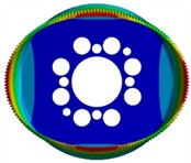
b) 8th modal shape

c) 9th modal shape
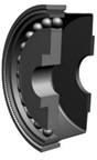
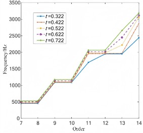
In order to analyze the influence of structural parameters on the natural frequency of the flexible wheel, single-factor modal analysis is carried out under different length of and thickness of , and the comparison results of natural frequencies are shown in Fig. 5 and Fig. 6. It can be seen that the natural frequency of the flexible wheel is greatly influenced by the structural parameters such as the cylinder length and the cylinder wall thickness. The influence of the structure parameters of the flexible wheel on the different modes of the flexible wheel is different. The wall thickness of the flexible wheel can significantly improve the natural frequency of the tensile vibration mode at the bottom of the flexible wheel. When the length of the flexible wheel cylinder is shorter and the wall thickness of the cylinder is bigger, the natural frequency of the flexible wheel under most modes is bigger. Therefore, when designing the structure of harmonic reducer working at high speed, the natural frequency of the flexible wheel can be improved by adjusting the structure size of the flexible wheel to avoid resonance of the harmonic reducer, so as to improve the stability of harmonic gear transmission.
Fig. 5Natural frequency under different length
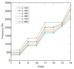
Fig. 6Natural frequency under different thickness
The first three effective mode shapes of the rigid wheel are shown in Fig. 7. It can be seen from the research results that the vibration displacement is mainly radial and axial bending. The first effective natural frequency is 3689.1 Hz, which is much higher than that of the flexible wheel. Both the stiffness and yield strength are relatively large, so the probability of resonance is relatively small. To further ensure the stability of the structure, it is necessary to analyze the load response of the flexible wheel.
Fig. 7Results of the first three modal shapes of rigid wheel
a) 7th modal shape (3689.1 Hz)
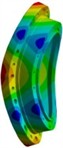
b) 8th modal shape (3723.4Hz)
c) 9th modal shape (4158.3 Hz)
3.3. Load response analysis of flexible wheel
The axial length of the flexible wheel is an important factor affecting the stress in all directions of the flexible wheel, which will limit the application of the harmonic reducer in the compact space scene. Under the condition of keeping other structural parameters unchanged, the finite element analysis model of harmonic reducer with different cylinder length is established, and then the rated torque of 150 N∙m is applied at the cylinder bottom to analyze the influence of cylinder length on the stress of flexible wheel, bearing stress and torsional rigidity. Through finite element analysis, the stress field nephogram of 40 mm and 60 mm in length is shown in Fig. 8(a) and Fig. 8(b). The stress nephogram of the flexible wheel under different wall thicknesses is shown in Fig. 8(c) and Fig. 8(d). It can be seen that the stress concentration positions of the flexible wheel are mainly distributed at the tooth root of the gear ring, the cylinder and the thin-wall of the cylinder bottom. The stress at the gear ring position is the maximum. The shorter the cylinder length is, the higher the stress concentration area of the flexible wheel is, and the more uneven the stress distribution of the cylinder is. Therefore, it is necessary to reasonably select the length of the flexible wheel according to the actual use requirements, so as to obtain a relatively good stress distribution. The change rules of maximum stress and torsional stiffness of flexible wheel under different axial lengths are shown in Fig. 9 and Fig. 10. It can be seen that, with the increase of the cylinder length, the maximum equivalent stress of each key part of the flexible wheel gradually decreases. The longer cylinder length can alleviate the effect of the bottom constraint of the flexible wheel on the deformation of the flexible wheel gear ring and the flexible wheel cylinder, and structurally reduce the inclination angle of the flexible wheel assembly deformation, so that the stress distribution is more uniform, and the stress concentration in the key areas is relieved, thereby improving the fatigue life. With the increase of the length of the cylinder, the torque stiffness of the harmonic reducer is gradually reduced, because the capacity of the flexible wheel cylinder to resist torsional deformation is reduced, thereby reducing the overall torsional stiffness. Therefore, the design of a smaller cylinder length can improve the capacity of the cylinder to resist torsional deformation, thereby improving the torsional stiffness of the harmonic reducer.
Fig. 8Stress field under different length and thickness
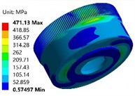
a) 40 mm
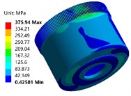
b)60 mm
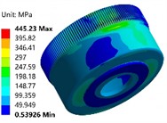
c)0.32 mm
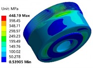
d)0.52 mm
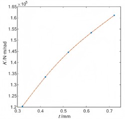
The change rules of maximum stress and torsional stiffness of flexible wheel under different axial lengths are shown in Fig. 11 and Fig. 12. It can be seen that the equivalent stress of the outer ring of the bearing gradually increases with the increase of the wall thickness of the cylinder. With the increase of the wall thickness of the flexible wheel cylinder, its resistance to bending deformation increases, and the assembly load of the flexible wheel to the bearing increases accordingly. Therefore, selecting a smaller wall thickness of the cylinder is conducive to reducing the stress of the bearing, thereby improving the fatigue life of the wave generator. With the increase of the wall thickness of the cylinder, the torsional rigidity of the harmonic reducer is gradually increased. Therefore, a larger wall thickness of the cylinder is conducive to improving the capacity of the flexible wheel cylinder to resist torsional deformation, thereby improving the torsional rigidity of the harmonic reducer.
Fig. 9The maximum stress under different length
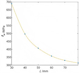
Fig. 10Torsional stiffness under different length
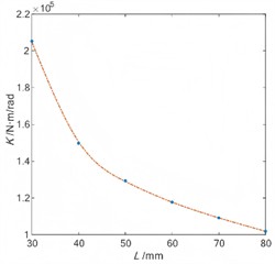
Fig. 11The maximum stress under different thickness
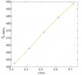
Fig. 12Torsional stiffness under different thickness
4. Conclusions
1) The modal analysis shows that the main vibration modes of the flexible wheel are the radial bending deformation of the flexible wheel gear ring and the cylinder body and the axial tensile deformation of the flexible wheel cylinder bottom. When the cylinder length is shorter and the cylinder wall thickness is larger, the natural frequency of the flexible wheel will be higher. The radial bending deformation and axial bending deformation of the rigid wheel are the main vibration modes, and the natural frequency is high, so the low frequency resonance problem will not occur.
2) The influence of key structural parameters on stress and torsional stiffness of flexible wheel is studied by single factor analysis method. The results show that increasing the cylinder length is beneficial to reducing the stress of the flexible wheel and the bearing, but reduces the torsional stiffness. In addition, reducing the wall thickness of the cylinder is beneficial to reducing the stress, but the torsional rigidity is also reduced.
References
-
Z. Yu, X. Wang, and Y. Zheng, “Design study on small transmission ratio harmonic reducer with new profile wave generator,” Proceedings of the Institution of Mechanical Engineers, Part C: Journal of Mechanical Engineering Science, Vol. 237, No. 15, pp. 3542–3560, Jan. 2023, https://doi.org/10.1177/09544062221147799
-
M. Ding, “Fast-slow dynamical analysis in harmonic gear transmission system with non-smooth gear clearance condition,” Current Journal of Applied Science and Technology, Vol. 42, No. 7, pp. 66–75, Apr. 2023, https://doi.org/10.9734/cjast/2023/v42i74082
-
H. Li, G. Wang, B. Wei, H. Liu, and W. Huang, “Improved variational mode decomposition method for vibration signal processing of flood discharge structure,” Journal of Vibration and Control, Vol. 28, No. 19-20, pp. 2556–2569, May 2021, https://doi.org/10.1177/10775463211016132
-
S. Gaygol and K. Wani, “Modal analysis of plate to analyze the effect of mass stiffeners using the Chladni plate approach,” Materials Today: Proceedings, Vol. 72, No. 3, pp. 1314–1321, Jan. 2023, https://doi.org/10.1016/j.matpr.2022.09.305
-
X. Li, D. Zhao, H. Zhai, M. Chen, and T. Zhang, “Modal analysis of circular arches in rectangular coordinate system,” Structures, Vol. 47, No. 1, pp. 2129–2137, Jan. 2023, https://doi.org/10.1016/j.istruc.2022.12.036
-
J. Mieloszyk, A. Tarnowski, and T. Goetzendorf-Grabowski, “Designing aerodynamic devices for UAV – lessons learned,” Aircraft Engineering and Aerospace Technology, Vol. 96, No. 1, pp. 73–83, Feb. 2024, https://doi.org/10.1108/aeat-02-2023-0060
-
M. Sari, H. L. Guntur, and M. B. S. Pratama, “Normal modes study on half wing structure of N219 aircraft using computational method,” International Conference on Mechanical Engineering, Vol. 125, No. 1, pp. 81–86, Mar. 2023, https://doi.org/10.4028/p-pnp9pp
About this article

The authors have not disclosed any funding.
The datasets generated during and/or analyzed during the current study are available from the corresponding author on reasonable request.
The authors declare that they have no conflict of interest.
