Abstract
Oil and gas pipelines, as vital arteries for energy transportation, play a crucial role in ensuring the supply of energy. However, under harsh geological conditions and external forces, the pipeline's anti-corrosion layer is susceptible to damage, particularly the destruction caused by external forces such as rockfall. This study focuses on the performance of a new type of anti-corrosion material-Fiber Reinforced Polymer (FRP) coating-under rockfall scratch, and compares it with Polyethylene (3PE) coating. By establishing a three-dimensional finite element model of the pipeline and rockfall, the study simulates the scratch process of rockfall on FRP and 3PE coated pipelines, analyzing the impact of various parameters on the coating damage. The results indicate that the FRP coating has a significant advantage in resisting rockfall damage, effectively dispersing and absorbing the impact force, thereby reducing damage. Moreover, parameters such as rockfall moving velocity, angle, penetration depth, and coating thickness significantly affect the degree of damage to the FRP coating. This research provides theoretical basis and technical support for the protection of oil and gas pipelines, which is of great importance for enhancing the safety and reliability of pipelines.
1. Introduction
In the field of oil and gas pipeline research, China has become the world's third-largest pipeline nation and has developed a pipeline technology system adapted to the characteristics of China’s oil and gas [1]. The expanding economy and energy demands are projected to increase the pipeline network to 210,000 km by 2025, necessitating advanced anti-corrosion materials, especially in challenging areas where traditional coatings fail. Jing H et al. emphasized the importance of coating treatment in pipeline corrosion protection [2], while Islam identified safety risks, including corrosion, and proposed protective measures such as improving material quality and anti-corrosion strategies [3]. Wen’s research on P110 steel in a CO2-rich environment used SEM and electrochemical methods to study corrosion, crucial for developing anti-corrosion strategies [4].
Rockfall is a significant geological hazard to buried pipelines, causing severe damage and affecting safe operation [5, 6]. Simulations using finite element software analyzed the mechanical changes of pipelines under rockfall impacts, varying parameters like impact speed, wall thickness, and burial depth [7]. The results indicated that stress, strain, and indentation velocity peak increase with rockfall speed and decrease with wall thickness and burial depth, providing technical support for pipeline protection under complex geological conditions [8].
Aghajani discussed detection and repair techniques for pipeline corrosion, offering a scientific basis for maintenance [9]. FRP materials are expected to innovate and expand in applications, particularly in new energy, 5G communication, and biomedicine, with high-performance thin films, conductive coatings, and biocompatible materials seeing greater development [10]. Given rockfall’s threat to pipelines and FRP coatings’ potential advantages, research on rockfall scratch to FRP-coated pipelines is essential [10]. Finite element simulation can simulate rockfall scratch on FRP and PE-coated pipelines, analyzing parameter impacts on coating damage, providing a theoretical basis for pipeline protection and optimizing design for enhanced damage resistance, reducing accidents, and ensuring energy and environmental security [11]. This study aims to analyze FRP coating performance under rockfall scratch compared to 3PE coatings, offering new solutions and technical guidance for pipeline protection.
2. Materials and methods
2.1. Problem statement
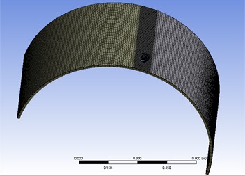
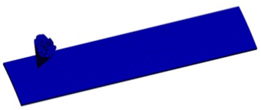
Before proceeding with finite element simulation analysis, it is essential to establish the geometric model of the pipeline. The pipeline consists of an anti-corrosion coating and a steel pipe, with the steel pipe having a radius of 762 mm and a thickness of 17.5 mm. The anti-corrosion layer is made of either epoxy resin glass fiber or polyethylene material, with a thickness of 3 mm. The rockfall is simplified into a conical shape, which slides over the pipeline at a specific angle and velocity.
Once the model is established, meshing is carried out as shown in Fig. 1. Meshing is a crucial step in finite element analysis, directly affecting the accuracy and efficiency of the calculations. A mesh size of 20 mm and tetrahedral element types are selected for meshing the model. Considering the potential stress concentration areas that may exist during the impact process, local mesh refinement is performed in the area where the steel pipe and the anti-corrosion layer meet to enhance computational accuracy.
Define the properties of various materials. This includes the density, Young’s modulus, Poisson's ratio, and tensile yield strength of structural steel, polyethylene (3PE), epoxy resin glass fiber (FRP), and granite. These parameters are of paramount importance for the accuracy of the simulation results, as shown in Table 1.
Fig. 1Finite element mesh of the model
The area where the falling rock comes into contact with the pipe can be compared to the contact between a conical punch and an elastic half-space. The radius of the contact circle and the vertical displacement (settlement) of the punch can be estimated using the following formula:
where is the radius of the contact circle, is the vertical displacement of the punch, is the apex angle, is the contact pressure, is the Poisson’s ratio, and is the shear modulus of elasticity.
Table 1Material properties
Material | Density (kg/m³) | Young’s modulus (GPa) | Poisson’s ratio | Tensile yield strength (MPa) |
Structural steel | 7850 | 200 | 0.3 | 250 |
Polyethylene (3PE) | 950 | 1.1 | 0.42 | 25 |
Epoxy resin glass fiber (FRP) | 2000 | 45(X) 10(Y) 10(Z) | 0.3(XY) 0.4(YZ) 0.3(XZ) | 1100 35 35 |
Granite | 3000 | 34 | 0.23 | – |
2.2. Numerical results
To analyze the anti-corrosion protection effects of glass fiber material and polyethylene material on pipelines, a scratch test was conducted on pipelines covered with anti-corrosion layers at a speed of 5 m/s. Both anti-corrosion layer materials have a thickness of 3 mm, with all other conditions being identical. The stress of both 3PEand FRP anti-corrosion layer under scratch results are shown in Figs. 2-3.
Fig. 2Stress of 3PE anti-corrosion layer under scratch
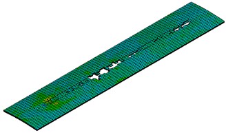
a) Equivalent stress
b) The first principal stress
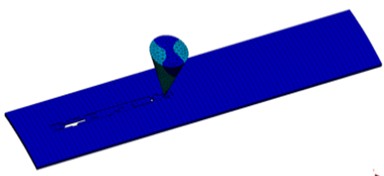
Fig. 3Stress of FRP anti-corrosion layer under scratch
a) Equivalent stress
b) The first principal stress
From the simulation results, we can see that when the 3PE material is scratched by a falling rock, its equivalent stress reaches 69.14 MPa, which is a relatively high value, indicating that under the impact of the falling rock, the 3PE material undergoes significant stress. At the same time, the maximum principal stress is 29.09 MPa, and the minimum principal stress is 90.9 MPa. This uneven distribution of stress may lead to local damage to the material, thereby losing its protective function for the internal pipeline. This kind of damage may be due to the insufficient ductility of the 3PE material, which cannot effectively disperse the impact force in areas of high stress concentration.
In comparison, the equivalent stress of the FRP material when scratched by a falling rock is 59.69 MPa, which is lower than that of the 3PE material, showing better impact resistance. The maximum principal stress of the FRP material is 60.45 MPa, and the minimum principal stress is 75.77 MPa. This more uniform stress distribution helps the material maintain its integrity when impacted. The simulation results show that the FRP layer did not suffer damage under the impact of falling rocks and was able to effectively deflect the rocks, with internal stress quickly dropping to a low level, indicating that the FRP material is significantly superior to the 3PE material in terms of resistance to rock impact damage.
In practical applications, this means that when designing oil and gas pipelines, if the possibility of external impacts such as falling rocks is considered, choosing FRP material as the anti-corrosion layer is a more reliable option. The characteristics of the FRP material make it more valuable in high-risk areas, such as mountainous regions and slopes prone to rockfalls. Therefore, we will only study the FRP material in the future.
3. Results and analysis
In order to more intuitively observe the degree of pipeline damage risk, the following danger factor coefficients is defined:
where is the danger factor, is the maximal equivalent stress of the pipeline. Safety factor is taken as 1.25, and yield stress of the material is 520 MPa.
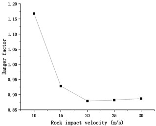
The magnitude of the rock moving velocity is related to the material's dissipation capability. To investigate the extent of the moving velocity on the deformation of the pipeline, numerical simulations are conducted with different values of rock velocity. The values taken for rock velocities are: 10 m/s, 15 m/s, 20 m/s, 25 m/s and 30 m/s. The results of the numerical simulations are shown in Fig. 4.
Investigating pipeline coating damage from falling rocks reveals a complex relationship between rock velocity and coating damage. Data analysis shows that while increasing rock velocity enhances impact force, the equivalent stress and danger factor paradoxically decrease. Specifically, as rock velocity rises from 10 m/s to 30 m/s, equivalent stress drops from 485.75 MPa to 369 MPa, and danger factor fall from 1.167668 to 0.887019. This suggests that the coating material disperses and absorbs impact more effectively at higher velocities, reducing damage. Additionally, at 20 m/s and 25 m/s, equivalent stress and danger factor are similar, suggesting a stabilization in coating damage behavior within this velocity range.
Since epoxy resin glass fiber is an anisotropic material, the angle between the direction of falling rock velocity and the damage strength is different. To study the extent of the impact of falling rock velocity on the layer angle, numerical simulations are conducted with different values of the angle. The angles taken are the angles between the falling rock velocity and the -axis, with values of 0°, 15°, 30°, 45°, 60°, 75°, and 90°. The results of the numerical simulations are shown in Fig. 5.
Fig. 4Variations of danger factor with rock impact velocity
Analyzing the effect of rock impact angles on pipeline coatings, it's evident that damage patterns are not linear. At a 0-degree impact, the coating endures peak stress (485.75 MPa) and danger factor (1.167668). This reduces at a 15-degree angle to 351.61 MPa and 0.845216, respectively. However, at 30 degrees, there’s an increase to 465.58 MPa and 1.119183. The coating sustains the most severe damage at a 45-degree impact, with peak values of 729.83 MPa and 1.754399. From 60 to 75 degrees, equivalent stress and danger factor decrease to 424.66 MPa and 1.020817, and 472.56 MPa and 1.135962, respectively. At a 90-degree impact, equivalent stress is 641.4 MPa and the danger factor is 1.541827, indicating significant but less severe damage than at 45 degrees.
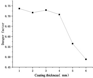
To study the extent of the impact of the depth of rock impact on the coating damage, numerical simulations are conducted with different values of impact depth. The impact depth is set to 1 mm, and the coating thickness values are taken as: 1 mm, 2 mm, 3 mm, 4 mm, 5 mm, 6 mm. The results of the numerical simulations are shown in Fig. 6.
In the study of the damage to pipeline coatings caused by falling rocks, it has been observed that there is a significant relationship between the thickness of the coating and the damage to the coating when the depth of the scratch is 1 mm. By analyzing the data provided in the figures, we can observe that as the thickness of the coating increases, the equivalent stress and danger factor show a certain trend of change.
Specifically, when the thickness of the coating increases from 1 mm to 6 mm, the equivalent stress decreases from 306.53 MPa to 203.03 MPa, while the danger factor decreases from 0.736851 to 0.488053. This indicates that as the thickness of the coating increases, the degree of damage to the coating is reduced. The decrease in equivalent stress and danger factor suggests that a thicker coating can more effectively disperse and absorb the impact force of the falling rock, thereby reducing the damage to the coating.
Fig. 5Variations of danger factor with rock scratch angle
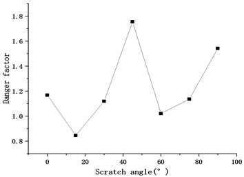
Fig. 6Variations of danger factor with coating thickness
4. Conclusions
This study comprehensively examines the effects of rockfall on oil and gas pipelines, comparing fiber-reinforced polymer (FRP) and polyethylene (3PE) materials through theoretical and numerical analysis. It highlights FRP's superior resistance to rockfall scratch and analyzes how parameters like rockfall velocity, angle, scratch depth, and coating thickness affect pipeline integrity, offering a theoretical and technical foundation for pipeline design and maintenance.
Parametric analysis of rockfall impact on FRP-coated pipelines revealed significant relationships between rockfall velocity and coating damage. Equivalent stress and danger factor change with increasing velocity, stabilizing at 20-25 m/s. The angle of rockfall also significantly affects damage, with maximum equivalent stress and hazard at 45 degrees. Thicker coatings were found to reduce equivalent stress and hazard, suggesting their effectiveness in mitigating rockfall impacts.
The study’s findings are crucial for predicting rockfall impacts on pipeline coatings and guiding pipeline design and maintenance. It recommends prioritizing FRP for anti-corrosion layers in oil and gas pipelines and tailoring coating thickness and structure in high-risk areas to enhance pipeline safety and reliability.
References
-
J. Zhang, Z. Liang, C. Han, and H. Zhang, “Buckling behaviour analysis of a buried steel pipeline in rock stratum impacted by a rockfall,” Engineering Failure Analysis, Vol. 58, No. 1, pp. 281–294, Dec. 2015, https://doi.org/10.1016/j.engfailanal.2015.09.009
-
M. Ali Khan, Z. Mustaffa, I. Sati Hamonangan Harahap, and M. E. A. Ben Seghier, “A comprehensive approach for understanding debris flow interaction with pipelines through dynamic impact pressure modeling,” Engineering Failure Analysis, Vol. 162, p. 108383, Aug. 2024, https://doi.org/10.1016/j.engfailanal.2024.108383
-
M. A. Islam and Z. N. Farhat, “Characterization of the corrosion layer on pipeline steel in sweet environment,” Journal of Materials Engineering and Performance, Vol. 24, No. 8, pp. 3142–3158, Jun. 2015, https://doi.org/10.1007/s11665-015-1564-4
-
F. Jiang, S. Dong, and C. G. Soares, “A probability-based study on failure mechanism and quantitative risk analysis for buried offshore pipelines subjected to third-party impact loads, exploring the effects of spatial variability of soil strength,” Marine Structures, Vol. 99, p. 103719, Jan. 2025, https://doi.org/10.1016/j.marstruc.2024.103719
-
D. Permadi, S. P. Fitri, and W. Busse, “Simulation of double walled pipe impact to crude oil flow in subsea pipeline system,” International Journal of Marine Engineering Innovation and Research, Vol. 2, No. 3, Jun. 2018, https://doi.org/10.12962/j25481479.v2i3.2721
-
A. Yao, T. Xu, X. Zeng, and H. Jiang, “Numerical analyses of the stress and limiting load for buried gas pipelines under excavation machine impact,” Journal of Pipeline Systems Engineering and Practice, Vol. 6, No. 3, pp. 1–7, Aug. 2015, https://doi.org/10.1061/(asce)ps.1949-1204.0000137
-
M. S. Chapot, R. Sohbati, A. S. Murray, J. L. Pederson, and T. M. Rittenour, “Constraining the age of rock art by dating a rockfall event using sediment and rock-surface luminescence dating techniques,” Quaternary Geochronology, Vol. 13, pp. 18–25, Dec. 2012, https://doi.org/10.1016/j.quageo.2012.08.005
-
Y.J. Yang, G.H. Liu, P. Yu, C. Huang, and L. Li, “Dynamic response and safety analysis of polyethylene pipeline under rockfall conditions,” Quality and Reliability Engineering International, Vol. 39, No. 5, pp. 2044–2068, May 2023, https://doi.org/10.1002/qre.3383
-
S. Aghajani, C. Wu, Q. Li, and J. Fang, “Additively manufactured composite lattices: A state-of-the-art review on fabrications, architectures, constituent materials, mechanical properties, and future directions,” Thin-Walled Structures, Vol. 197, p. 111539, Apr. 2024, https://doi.org/10.1016/j.tws.2023.111539
-
Y. Wang, M. Xie, and C. Su, “Dynamic reliability evaluation of buried corroded pipeline under rockfall impact,” Eksploatacja i Niezawodność – Maintenance and Reliability, Vol. 24, No. 2, pp. 275–288, Jun. 2022, https://doi.org/10.17531/ein.2022.2.9
-
Z. Yang, J. Yu, J. Duan, and H. Chen, “Experiment and numerical simulation for full-scale submarine pipeline with impact damage,” Journal of Tianjin University, Vol. 51, No. 12, pp. 1260–1265, 2018, https://doi.org/10.11784/tdxbz201712024
About this article

The authors have not disclosed any funding.
The datasets generated during and/or analyzed during the current study are available from the corresponding author on reasonable request.
The authors declare that they have no conflict of interest.
