Abstract
To solve the issue of abnormal vibration while accelerating during the development of a certain vehicle model, this paper utilizes the transfer path analysis (TPA) method to identify the key factors contributing to abnormal noise and vibrations within the vehicle. Through a combination of theoretical derivation and simulation analysis, the study examines the dynamic characteristics of the vehicle’s attachment points, particularly focusing on the shock absorber mounting locations. Based on the findings, a specific method for optimizing the dynamic stiffness of these attachment points is proposed. This optimization significantly improves the vehicle’s NVH (Noise, Vibration, and Harshness) performance, thereby reducing unwanted noise and enhancing the overall comfort and driving experience. The paper offers valuable insights and practical solutions to improve vehicle development processes and ensure superior NVH outcomes.
1. Introduction
As the continuous improvement of vehicle NVH (Noise, Vibration, Harshness, NVH) levels, traditional powertrain noise, wind noise, and road noise have been significantly controlled. Customers are gradually paying more attention to some issues closely related to subjective feelings [1]. As an important performance indicator in vehicle design, automobile driving comfort is an item that needs to be considered during vehicle development. More and more OEMs are paying attention to driving comfort during vehicles production.
The research on the dynamic stiffness of vehicle body attachment points is critical to improve the rigidity and stability of the overall vehicle structure. Many researchers are trying to propose innovative methods to optimize and improve the dynamic stiffness of attachment points, including analyzing the distribution of vehicle body stiffness and its impact on NVH performance through advanced simulation and testing technology [2]. In recent years, the application of simulation technology, vehicle dynamics models and advanced sensor technology has brought the research on the dynamic stiffness of vehicle body attachment points into a new stage.
This paper aims to solve the problem of abnormal floor shaking during deceleration and acceleration of a certain vehicle model. Through the transfer path analysis method, the key factors affecting the abnormal acceleration shaking in the car are determined. By optimizing the installation stiffness of the front shock absorber, the noise problem caused by the abnormal shaking during acceleration in the car is solved, which provides important theoretical basis and technical support for the optimization of vehicle NVH performance.
2. Phenomenon description and transfer path analysis
2.1. Phenomenon description
In the subjective evaluation of a certain vehicle model, testers detected a significant whine during vehicle acceleration, accompanied with abnormal vibration in the vehicle floor. This severely affected the driving comfort of the occupants, which is unacceptable in the subjective evaluation stage. In the objective evaluation tests, we found that the abnormal noise and vibration generated during acceleration were concentrated within the frequency range of 200 Hz. To accurately identify and resolve this issue, we employed the TPA method to conduct an in-depth analysis of the vehicle’s vibration transmission paths. The TPA method, through detailed analysis of vibration sources, transmission paths, and response points, effectively locates the root causes of noise and vibration issues to specific vibration sources and paths. Using this systematic approach, we were able to more precisely identify the cause of abnormal vibrations during acceleration and provide clear directions for subsequent optimization and improvement.
2.2. Transfer path analysis
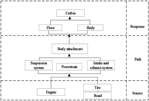
The whining noise experienced by the occupants inside the vehicle is primarily caused by the interaction of multiple vibration sources, which are transmitted through a complex series of pathways within the vehicle structure [3]. Vibrations generated by the engine, tire imbalance, and road surface irregularities are transmitted through the powertrain, suspension system, intake and exhaust systems, and the attachment points of the body, delivering vibrational energy to the body and floor, ultimately resulting in abnormal vibrations and noise inside the vehicle. The vibration transmission path is shown in Fig. 1. These phenomena are particularly pronounced during acceleration, when the vehicle is under load and the vibrational forces are amplified, making the discomfort more noticeable to the passengers.
Therefore, the dynamic characteristics of the attachment points between the vehicle body and various vibration sources are crucial. The main attachment points of the vehicle body include the engine mount points, suspension system mounting points, exhaust system mounting points, etc. Optimizing the design of these attachment points can effectively control the transmission of vibration energy, reduce noise and vibrations inside the vehicle, and thus improve the overall comfort and driving experience [4].
Fig. 1Vibration transmission path
2.3. Dynamic stiffness theory
Dynamic stiffness analysis involves applying a unit force as an input excitation at a loading point within a certain frequency range, while using that point as the response point to measure the input point inertance (IPI) at the corresponding frequency range. This is used to examine the local dynamic stiffness at that point. [5]
The dynamic stiffness is defined as:
IPI is defined as:
where is the acceleration, is the force (input excitation), is the displacement, is the frequency, is the angular frequency.
Dynamic stiffness is a quadratic function of the excitation frequency and the area enclosed by the response curve (between the upper frequency limit and lower frequency limit ) is given by:
The average dynamic stiffness of the mounting point is:
For a linear system, stiffness is represented as the ratio of the load force applied to the system and the resulting deformation , i.e., . Dynamic stiffness analysis is based on modal frequency response methods, applying unit force at the mounting point of the suspension pad and setting the frequency range for analysis [6].
In vibration analysis, dynamic stiffness represents the stiffness characteristics of a structure under dynamic loading. It not only considers static stiffness but also factors such as frequency and damping. The analysis of body attachment points dynamic stiffness focuses on the dynamic response characteristics of local regions, aiming to optimize structural design, reduce vibration transmission, and improve the vehicle’s NVH performance. This is significant for controlling vehicle vibration and noise [7].
3. Optimization of attachment point dynamic stiffness
3.1. Problem analysis
To find out the cause of abnormal vibration inside the vehicle, finite element simulation technology was used to perform IPI analysis on the key suspension points of the frame. First, a finite element model of the frame was established using Hypermesh, as shown in Fig. 2. Then, unit force was applied as the excitation source at each key mounting point, and the dynamic response of the mounting point in the frequency range of 0 Hz to 200 Hz was output, with particular attention paid to the frequency peak and valley. The calculator used was Optistruct.
Through simulation calculations, the dynamic stiffness of other vehicle mounting points meets the set target values, but the IPI at the three mounting points of the front shock absorber is lower than the target, as shown in Tables 1, 2, and 3.
Figs. 3, 4, and 5 are the dynamic response results of the installation point simulation calculation. Further analysis reveals dynamic stiffness valleys around 35 Hz and 60 Hz. Therefore, the source of the abnormal noise is identified as the frontshock absorber.
Fig. 2Finite element model of the frame
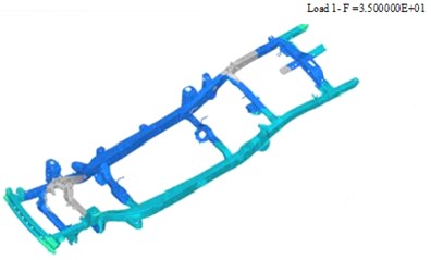
Table 1IPI of front shock absorber front mounting points
Point ID | (N/mm) | (N/mm) | (N/mm) |
4110 | |||
Simulation value | 14142 | 9910 | 13797 |
Target value | 10000 | 5000 | 15000 |
Table 2IPI of front shock absorber left rear mounting points
Point ID | (N/mm) | (N/mm) | (N/mm) |
4130 | |||
Simulation value | 16516 | 25869 | 17464 |
Target value | 20000 | 10000 | 10000 |
Table 3IPI of front shock absorber right rear mounting points
Point ID | (N/mm) | (N/mm) | (N/mm) |
4140 | |||
Simulation value | 15401 | 21634 | 10755 |
Target value | 20000 | 10000 | 10000 |
The dynamic stiffness of the source point includes not only the local response of the point itself, but also the semi-global and global responses of the entire vehicle body structure. If the dynamic stiffness of the source point of the mounting point fails to meet the design requirements, the response characteristics of the point in different frequency bands can be analyzed to identify the frequency bands in which it fails to meet the target requirements, and then the local structure can be adjusted to meet the design requirements.
Fig. 3Dynamic stiffness curve in Z direction of front shock absorber mounting point (front)
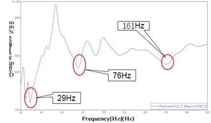
The analysis results of the dynamic stiffness of the installation point show that the dynamic stiffness of the front shock absorber installation point in the and directions does not meet the design target requirements, which has an adverse effect on the overall NVH performance of the vehicle body. Therefore, the dynamic stiffness of the front shock absorber installation point needs to be increased to meet the target requirements and improve the overall comfort of the vehicle.
Fig. 4Dynamic stiffness curve in X direction of front shock absorber mounting point (left rear)
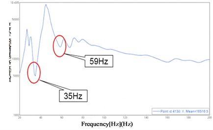
Fig. 5Dynamic stiffness curve in X direction of front shock absorber mounting point (right rear)

3.2. Structure optimization
Based on the optimization cost considerations and combined with engineering experience, this paper proposes a solution to optimize the dynamic stiffness of the front shock absorber installation point to improve the impact of its insufficient dynamic stiffness on the NVH performance of the vehicle body. The main goal is to enhance the dynamic stiffness of the front shock absorber installation point to meet the design requirements. This paper proposes a structure-based optimization method. By changing the installation point structure on the simulation software, the change of dynamic stiffness is monitored until the design requirements are met.
At the front mounting point of the shock absorber, the overlap on the bracket is extended by 12 mm, and a 3 mm high rib is added. The plane of the overlap below is raised. As shown in the figure, the bracket is thickened by 4mm and the crossbeam is thickened by 3 mm to further improve the deformation resistance of the attachment point, shown as Fig. 6.
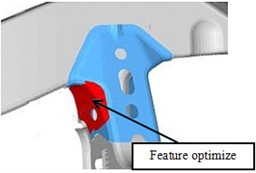
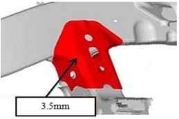
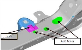
For the rear mounting point of the shock absorber, the mounting beam joint lap part is thickened to 3.5 mm, and the changes are symmetrical on the left and right; the features of the lap position between the bracket and the beam surface are optimized, and the beam is supplemented with holes, aiming to reduce the negative impact of vibration transmission on the body structure by improving the overall stiffness of the connecting parts. Fig. 7 shows the structural diagram of the front shock absorber mounting point based on the optimization scheme in detail.
In order to verify the feasibility of the optimization scheme, the dynamic stiffness of the source point in the , , and directions of the shock absorber installation point after optimization is calculated. Table 6 shows the IPI results in each direction after optimization.
Fig. 6Optimization of front mounting point
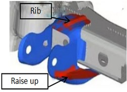
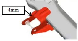
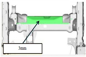
Fig. 7Optimization of rear mounting points
By contrasting the IPI of the mounting point after optimization, it can be seen that the dynamic stiffness changes significantly after the target direction of the mounting point is optimized, and it meets the NVH design goals. It has been verified by the vehicle test that after optimizing the inching stiffness of the suspension installation, the abnormal acceleration jitter in the vehicle disappears, the noise level in the vehicle is significantly improved, and the overall comfort and driving experience of the vehicle are significantly improved.
Table 4Front mounting points
Point ID | (N/mm) | Change (N/mm) |
4110 | ||
Target value | 15000 | / |
Initial value | 13797 | / |
Optimization | 15174 | +456 |
Table 5Left rear mounting point
Point ID | (N/mm) | Change (N/mm) |
4130 | ||
Target value | 20000 | / |
Initial value | 16516 | / |
Optimization | 20385 | +3869 |
Table 6Right rear mounting point
Point ID | (N/mm) | Change (N/mm) |
4140 | ||
Target value | 20000 | / |
Initial value | 15401 | / |
Optimization | 20047 | +4646 |
4. Conclusions
In response to the abnormal vibration and noise in the vehicle during acceleration, this paper analyzes the vibration transmission path, locates the key factors that cause abnormal noise in the vehicle, uses finite element simulation technology to calculate the dynamic stiffness of the vehicle front shock absorber installation point and simulates the optimization scheme, and proposes an optimization scheme for the installation point on the basis of controlling the overall structure of the frame and development cost. The main conclusions are as follows:
1) The dynamic stiffness results of the optimized shock absorber installation point meet the target value of NVH design, indicating that the optimization scheme proposed in this paper can effectively improve the dynamic stiffness of the frame and solve the problem of abnormal noise in the vehicle during acceleration.
2) After the abnormal noise problem is found, the transfer path analysis method can quickly locate the root cause of the abnormal noise problem, so as to carry out targeted optimization analysis and improve vehicle quality.
References
-
J. Masri, M. Amer, S. Salman, M. Ismail, and M. Elsisi, “A survey of modern vehicle noise, vibration, and harshness: A state-of-the-art,” Ain Shams Engineering Journal, Vol. 15, No. 10, p. 102957, Oct. 2024, https://doi.org/10.1016/j.asej.2024.102957
-
W. L. Lou, X. Wang, and H. X. Liu, “Optimization analysis of dynamic stiffness of attachment point of minibus body-in-white,” Mechanical Design and Manufacturing, pp. 217–219, 2014.
-
J. Z. Lin, F. Zeng, and J. Weng, “IPI analysis and structural optimization of powertrain suspension bracket,” Electromechanical Technology, pp. 64–67, 2021.
-
B. Liu et al., “Strength simulation analysis and structural optimization of powertrain suspension bracket based on vehicle durability test road conditions,” Automotive Parts, Vol. 11, pp. 27–30, 2017.
-
Y. F. Qin, “Optimal design of body-in-white dynamic stiffness based on IPI area sensitivity analysis,” Equipment Manufacturing Technology, Vol. 10, pp. 43–46, 2023.
-
G. Papaioannou et al., “Dynamic performance analysis of vehicle seats with embedded negative stiffness elements,” Vehicle System Dynamics, 2020.
-
H. Lian et al., “Optimal design of dynamic stiffness of rear subframe motor front suspension installation point based on strain energy analysis,” Equipment Manufacturing Technology, Vol. 12, pp. 127–130, 2022.
About this article

The authors have not disclosed any funding.
The datasets generated during and/or analyzed during the current study are available from the corresponding author on reasonable request.
The authors declare that they have no conflict of interest.
