Abstract
This study explores novel concretes where cement is partially replaced by oil shale ash (OSA), reducing CO2 emissions, and incorporates patented composite fibers for enhanced mechanical performance. The mechanics of fiber pull-out and interfacial bond strength in concrete reinforced with short fibers, where cement is partially replaced by either fly ash or OSA, using the Double Cantilever Beam (DCB) test. The research aims to assess how these eco-friendly additives impact the fiber-matrix bond and crack propagation resistance in fiber-reinforced concrete. In the experimental setup, two partially sawn concrete beams were joined along their length by a thin, fiber-reinforced concrete layer and subjected to a tensile force, simulating crack opening. Concrete specimens (400×210×100 mm) with varying ash contents were tested, focusing on key parameters such as peak load, energy absorption, and interfacial toughness. Findings indicate that both fly ash and basalt enhance the mechanical properties of the concrete, with significant improvements in load transfer and fiber pull-out resistance observed, particularly at higher ash contents. Analysis of force-displacement curves and fracture surfaces demonstrated a shift from brittle to more ductile behavior as ash content increased, enhancing the fracture resistance of the composite. This research supports the use of alternative cementitious materials like fly ash and basalt in developing sustainable, high-performance fiber-reinforced concrete, with potential applications in structural engineering and eco-friendly construction practices.
1. Introduction
Concrete reinforced with composite fibers has gained significant interest for its enhanced mechanical properties, including improved tensile strength, durability, and fracture resistance, making it suitable for structural applications under dynamic loading. When mechanical load is applied to the fiber concrete structure, one or few macrocracks appear and begin to open. The fibers are bridging them, preventing the structure from splitting into parts. Important is to know load - fiber pulled out length dependence law on fiber orientation to opening crack’s plane surface. Traditional way of investigation is to perform single fiber pull-out experimental tests. Development of that approach to few simultaneously pulled out fibers is Double Cantilever Beam (DCB) test. This study examines the pull-out behavior of composite fibers in concrete partially substituted with sustainable cementitious materials – specifically, fly ash and oil shale ash-using the Double Cantilever Beam (DCB) test to assess interfacial bond strength and fiber-matrix interaction. By integrating fibers with SCMs, the composite material exhibits increased toughness, energy absorption, and crack resistance, benefiting from both the bridging effect of fibers and the pozzolanic properties of the SCMs [1-3].
Results from pull-out testing reveal that fly ash and oil shale ash significantly enhance the interfacial bond strength, fracture toughness, and durability of fiber-reinforced concrete (FRC), providing insights into load transfer efficiency and debonding mechanics. Findings support the use of eco-friendly additives in producing high-performance FRC with potential for cost-effective, durable, and sustainable construction applications [4-7].
2. Materials and methods
The novelty of this work lies in developing sustainable concretes by partially replacing cement with oil shale ash (OSA), a widely available waste material, significantly reducing CO2 emissions. Additionally, it introduces fiber-reinforced concretes utilizing patented novel composite fibers, enhancing mechanical performance and advancing eco-friendly construction technology.
2.1. Preparation of fiber
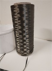
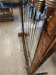
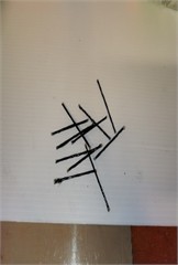
Basalt yarns were prepared by slightly twisting them together and securing them in a wooden frame equipped with dampers to maintain light tension. This setup helped to ensure that the fibers remained aligned during the treatment process. The yarns were then coated with a binding mixture of epoxy resin (WELA-EP 100) and hardener in a 3:1 ratio, promoting the formation of a uniform, resilient thread structure. Following application, the epoxy-coated fibers were left to dry for two days to achieve optimal strength and stability. Once fully cured, the fibers were cut into short segments, each measuring 4.8 cm in length, ready for incorporation into composite materials [8-9].
Fig. 1Preparation of Basalt fiber
2.2. Preparation of sample
In this study, concrete reinforced with basalt fibers was investigated to assess the effects of Oil Shale Ash (OSA) as a partial cement replacement on the material's mechanical properties, with a focus on compression and pull-out strength. OSA, a byproduct of oil shale combustion for energy production, possesses properties suitable for use as a mineral binder, making it a viable alternative to traditional cement. Concrete cubes were prepared for compression testing with OSA incorporated at replacement levels of 0 %, 15 %, and 35 %. Additionally, concrete beams measuring 400 mm×210 mm×100 mm were prepared, notched, and joined to simulate crack behavior under loading. Basalt fibers, coated with Wela EH08 hardener and cut into 48 mm segments, were added to the concrete mix to enhance toughness and fracture resistance. The varying OSA percentages allowed for a comparative analysis of mechanical properties, particularly focusing on interfacial bond strength and energy absorption, providing insights into the potential of OSA as a sustainable cementitious material in fiber-reinforced concrete [10, 11].
To prepare the concrete mixture, the components were measured according to the recipe outlined in Table 1. This included varying proportions of cement and oil shale ash as a partial cement replacement, alongside standard aggregates like gravel and sand. The specific mixtures were designated as DCA-0 (0 % oil shale ash), DCA-1 (15 % oil shale ash), and DCA-2 (35 % oil shale ash). All dry ingredients were weighed separately and added to a concrete mixer, while water and plasticizers were mixed in a separate container. The dry components were blended into a homogeneous mixture, with the remaining ingredients gradually introduced over a period [12].
Table 1Concrete mix composition
Material | DCA-0 (0 %) | DCA-1 (15 %) | DCA-2 (35 %) |
Cement | 7.625 kg | 6.48 kg | 4.955 kg |
Oil Shale Ash | 0 | 1.145 kg | 2.67 kg |
Water | 5 L | 5 L | 5 L |
Gravel (4-8 mm) | 26.15 kg | 26.15 kg | 26.15 kg |
Sand (0.3-2.5 mm) | 15.1 kg | 15.1 kg | 15.1 kg |
Sand (0.1 mm) | 2.85 kg | 2.85 kg | 2.85 kg |
Dolomite | 2.05 kg | 2.05 kg | 2.05 kg |
Plasticizer (Sika D-190) | 0.25 kg | 0.25 kg | 0.25 kg |
Before pouring the concrete, the mold was oiled to facilitate the removal of samples post-curing. The prepared cement paste was filled into the mold to a height of 25 mm, and four steel rebar pieces were positioned 20 mm from both edges and 20 mm from the center of the mold. At a height of 50 mm from the bottom, 15 fibers were inserted in three groups of five at a 45° angle. Another set of four steel bars was placed 75 mm from the bottom, maintaining the same configuration. The mold was then filled with concrete, covered with plastic wrap, and left to cure for two days. After this period, the samples were demolded and immersed in water for a curing duration of 28 days.
Once the curing process was complete, the samples were extracted from the water. Prior to testing, holes were drilled between the reinforcements in areas without fibers, and a small notch was cut in the center of the sample to ensure that failure would initiate at this point. The samples were then positioned in a universal testing machine, with clamps secured at the drilled holes. The setup allowed for a gradual increase in force until a crack developed along the designated path in the concrete. Upon reaching the critical load, the basalt fibers either fractured or pulled out from the concrete, demonstrating their behavior under tensile loading conditions [13, 14].
2.3. Testing procedure
Once the concrete specimens had cured for 28 days, specific notches were created at predetermined locations to direct the fracture path during testing. Each specimen was then equipped with clamps and tested using a Zwick Z150 electro-hydraulic universal testing machine. This machine applied a gradually increasing force at a rate of 5 mm per minute until a fracture developed within the concrete matrix. Throughout the process, both fiber pull-out and fracturing behaviors were closely monitored and recorded. The primary objective of this testing was to investigate the fiber pull-out behavior in concrete mixed with basaltic ash, a natural mineral additive that has the potential to enhance mechanical properties and durability while reducing environmental impact.
Fig. 2Testing setup of samples
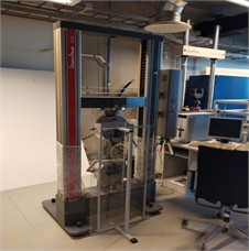
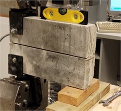
The Double Cantilever Beam (DCB) test was employed in this experimental setup, which is a mode I fracture test designed to measure the resistance of composite materials to crack propagation at the fiber-matrix interface. By splitting the specimen into two parts, with the embedded fibers forming a “double cantilever beam”, the interaction between the fibers and the concrete matrix could be thoroughly examined. As the test progressed, a non-contact video extensometer from Messphysik was used to measure pull-out displacement accurately. This methodology allowed for the precise recording of force and displacement data during the fiber pull-out process, facilitating the generation of force versus pull-out displacement diagrams. These results provide valuable insights into the pull-out forces and energy requirements, critical for predicting failure modes in fiber-reinforced concrete applications, such as in pavements and load-bearing structures. At the same time test is possible to designate as DCB only approximately, because when crack is opened (and bridged by fibers) each separated beam is not working as a cantilever, rotating around both beams mutual touching line [15, 16].
3. Results and discussion
The experiment focused on measuring the maximum force acting on basalt fibers embedded in concrete samples, identified as DCA-0, DCA-1, and DCA-2. The results from these samples are summarized in graphs where data on each specimen's performance under applied load is recorded.
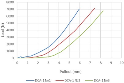
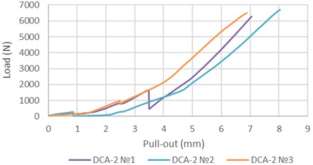
The analysis of force-displacement behavior among different material configurations reveals distinct performance characteristics. The DCA-0 group exhibits superior load-bearing capacity, reaching a maximum force of nearly 9000 N. This indicates its robustness, as it can withstand significant forces before substantial displacement occurs. In contrast, the DCA-1 group displays a rapid increase in force but achieves peak displacement more quickly, with a maximum force of approximately 7500 N. This suggests a lower stiffness compared to DCA-0, while the DCA-2 group consistently demonstrates the lowest force values across all displacements, peaking at just below 6000 N, indicating a lesser resistance to applied forces and possibly inferior material properties [17].
The non-linear relationship observed in the force-displacement curves indicates that as displacement increases, the rate of force increase also accelerates, a behavior commonly associated with strain hardening in composite materials. This trend implies that the materials exhibit increasing resistance to deformation with greater displacement, which is a critical factor in evaluating their mechanical properties. The variations in maximum forces among the configurations, along with the differences in their stiffness and displacement behavior, highlight the importance of material testing for engineering applications. Understanding these characteristics enables engineers to set safe loading limits and optimize material selection based on performance requirements, ultimately guiding the design of more resilient structures and components [18].
Fig. 3Results of samples with 0 % OSA
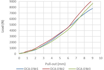
Fig. 4Results of samples with 15 % OSA
To analyze the load distribution on the fibers, a triangular loading configuration was observed (it is true on initial stage of pulling out process). This means that the force was not evenly distributed among the fibers; instead, a significant portion of the load was concentrated on the first fiber, while the last fibers experienced minimal loading. This uneven distribution can significantly impact the overall structural behavior and failure mechanisms of the composite material [19, 20].
Fig. 5Results of samples with 35 % OSA
The maximum force, denoted as , can be derived from the equation:
where: is the force acting on the nth fiber, is the distance from the th fiber to a reference point (zero), represents the shoulder length over which the load is applied. The summation calculates the total contribution of forces acting on all fibers in the system.
From the triangular load distribution, the relationship between the forces acting on successive fibers is given by:
This indicates that the force acting on any fiber can be expressed as a function of the force on the previous fiber, scaled by the ratio of their respective distances.
To find the force , we can rearrange the equation as follows:
Here, the denominator accounts for the contributions of all fibers, normalizing the forces based on their distances from the reference point.
When crack opening is reaching statement when first fibers are pulled out of the concrete, hypotheses about triangle load distribution must be corrected.
The data presented further elaborates on the results obtained from the DCA-0 and DCA-2 samples, indicating the performance of each underload condition. By analyzing these results, we can better understand how the force distribution affects the pull-out strength and overall performance of the fiber-reinforced concrete under tensile loading, ultimately aiding in optimizing the design and application of such composite materials in structural engineering [21-23].
This detailed examination of the load distribution and its effects is crucial for developing reliable fiber-reinforced concrete systems that can effectively withstand applied forces in real-world applications.
4. Conclusions
This study examines the mechanics of composite fiber pull-out from concrete incorporating oil shale ash, highlighting the complex interplay between sustainability and mechanical performance. The findings indicate that the inclusion of oil shale ash significantly diminishes fiber pull-out resistance, primarily attributed to its effects on the integrity of the concrete matrix and the bonding mechanisms between fibers and the concrete substrate.
Notably, the analysis of varying ash content reveals a threshold effect; specifically, the transition from 15 % to 35 % ash content yields diminishing returns concerning further reductions in pull-out resistance up to 1000 N for each consideration. This suggests that while higher ash content promotes ecological benefits, it may lead to compromised mechanical properties beyond a certain point.
Considering these results, future research should focus on optimizing the oil shale ash content to achieve an effective balance between the desired sustainability outcomes and the mechanical performance of the concrete composites. Additionally, the exploration of alternative additives that could enhance fiber bonding and mitigate the adverse effects of oil shale ash on pull-out resistance is recommended, such investigations will be crucial for developing concrete materials that are both environmentally sustainable and structurally resilient.
References
-
Krasnikovs, A., Kononova, O., Vagele, and A., “Numerical simulation of fiber pull out of elastic matrix with friction,” in 5th European Conference on Computational Mechanics, 2014.
-
A. Lukasenoks, A. Macanovskis, and A. Krasnikovs, “Composite carbon fibre embedment depth and angle configuration influence on single fibre pull-out from concrete,” in 17th International Scientific Conference Engineering for Rural Development, May 2018, https://doi.org/10.22616/erdev2018.17.n364
-
A. Macanovskis, A. Krasnikovs, O. Kononova, and A. Lukasenoks, “Mechanical behavior of polymeric synthetic fiber in the concrete,” Procedia Engineering, pp. 673–680, 2017.
-
V. C. Li and C. K. Y. Leung, “Steady‐state and multiple cracking of short random fiber composites,” Journal of Engineering Mechanics, Vol. 118, No. 11, pp. 2246–2264, Nov. 1992, https://doi.org/10.1061/(asce)0733-9399(1992)118:11(2246)
-
R. Siddique, “Performance characteristics of high-volume Class F fly ash concrete,” Cement and Concrete Research, Vol. 34, No. 3, pp. 487–493, Mar. 2004, https://doi.org/10.1016/j.cemconres.2003.09.002
-
P. K. Mehta, “Greening of the concrete industry for sustainable development,” Concrete International, Vol. 24, No. 7, pp. 23–28, 2002.
-
B. W.Wambeke, and C. K. Shield, “Double cantilever beam (DCB) test for bond strength of FRP laminates bonded to concrete,” Journal of Composites for Construction, Vol. 10, No. 1, pp. 78–86, 2006.
-
K. R. Kannathasan, S. J. M. Michaelraj, E. Gjerlow, I. Novakova, and M. Vaisnoras, “Hybrid fiber composite material with osa mechanical load-bearing capacity after thermal heating,” Latvia University of Life Sciences and Technologies, 2024.
-
K. R. Kannathasan, A. Krasnikovs, A. Macanovskis, and I. Novakova, “Mechanical behavior of Composite basalt short fiber for concrete structure reinforcement,” Environment. Technologies. Resources. Proceedings of the International Scientific and Practical Conference, Vol. 3, pp. 248–252, Jun. 2024, https://doi.org/10.17770/etr2024vol3.8157
-
K. Rengasamy Kannasthan, A. Krasnikovs, and A. Macanovskis, “Ingredients degradation in steel fiber reinforced concrete after thermal loading,” Nvironment. Technologies. Resources. Proceedings of the International Scientific and Practical Conference, Vol. 3, pp. 124–128, Jun. 2023, https://doi.org/10.17770/etr2023vol3.7228
-
K. Rengasamy Kannathasan, A. Macanovskis, R. Ralla, and E. Gjerlow, “Behavior of short fiber composite materials in variation of thermal and mechanical loading,” Environment. Technologies. Resources. Proceedings of the International Scientific and Practical Conference, Vol. 3, pp. 242–247, Jun. 2024, https://doi.org/10.17770/etr2024vol3.8151
-
V. Lusis et al., “Experimental study and modelling on the structural response of fiber reinforced concrete beams,” Applied Sciences, Vol. 12, No. 19, p. 9492, Sep. 2022, https://doi.org/10.3390/app12199492
-
N. Banthia and R. Gupta, “Test method for evaluation of plastic shrinkage cracking in fiber-reinforced cementitious materials,” Experimental Techniques, Vol. 31, No. 6, pp. 44–48, Nov. 2007, https://doi.org/10.1111/j.1747-1567.2007.00191.x
-
Shah, S. P., Naaman, and A. E., “Mechanical properties of glass and steel fiber reinforced mortar,” ACI Journal Proceedings, Vol. 73, No. 1, pp. 29–38, Jan. 1976, https://doi.org/10.14359/11055
-
Barr and B., “Fiber reinforced concrete,” in RILEM Symposium, 1992.
-
Reinhardt, H. W., Naaman, and A. E., “High performance fiber reinforced cement composites.,” in RILEM/ACI Workshop, 1992.
-
I. Nováková et al., “Investigating the influence of oil shale ash and basalt composite fibres on the interfacial transition zone in concrete,” Buildings, Vol. 14, No. 7, p. 1952, Jun. 2024, https://doi.org/10.3390/buildings14071952
-
S. Upnere, I. Novakova, N. Jekabsons, A. Krasnikovs, and A. Macanovskis, “Bridging law application to fracture of fiber concrete containing oil shale ash,” Buildings, Vol. 13, No. 7, p. 1868, Jul. 2023, https://doi.org/10.3390/buildings13071868
-
J. M. Gere and B. J. Goodno, Mechanics of Materials. Cengage Learning, 2012.
-
J. Doe and A. Smith, “Experimental study of DCB testing methods for composite materials,” Journal of Composite Materials, Vol. 54, No. 8, pp. 1234–1250, 2020.
-
K. K. Chawla, Composite Materials: Science and Engineering. Springer, 2013.
-
P. Balaguru and S. P. Shah, Fiber Reinforced Concrete. New York: Wiley, 1992.
-
V. C. Li and J. G. M. van Mier, “Fracture Mechanics of Concrete. Engineering Fracture Mechanics,” , Vol. 41, No. 1, pp. 1–30, 1992.
About this article

Authors acknowledge for financial support from the Baltic Research Program Project No. EEA-RESEARCH-165 “Innovation in concrete design for hazardous waste management applications” under the EEA Grant of Iceland, Liechtenstein, and Norway Project Contract No. EEZ/BPP/VIAA/2021/6 and Riga Technical university.
The datasets generated during and/or analyzed during the current study are available from the corresponding author on reasonable request.
The authors declare that they have no conflict of interest.
