Abstract
The vibration exciter is a structural component of a vibration machine, regardless of its technological application, that determines the operating mode of the machine. This paper presents the structural design of a controlled mechanical exciter of circular translational vibrations equipped with two unbalanced shafts. The operating principle of the proposed exciter is described. A mathematical model of the dynamic action of the exciter on the processed medium is developed, defining the dependence of the generated excitation on the rotation angle of the movable unbalanced masses relative to their initial positions.
1. Introduction
In various fields of human activity, technological machines are often an integral part of production processes. The vibration-induced action on the processed medium in them constitutes the basis, and in some cases the only feasible means, of carrying out the respective process. For many years, vibration machines and associated technologies have been used to perform a wide range of operations, including: (a) removal and rounding of burrs from sharp edges of various components; (b) vibration-assisted hardening and stabilization treatment; (c) grinding and polishing; (d) combined finishing and coating processes; (e) surface finishing to achieve a marketable appearance; (f) compaction or loosening of the processed medium; (g) comminution of solid materials; (h) separation of bulk materials according to size, shape, density, or coefficient of friction; (i) conveying; and other processes.
In certain production applications, such as forming, separation, or tumbling, there is a technological need to generate a vibration-induced action that causes all material elements of the processed medium to move within certain parallel planes while following non-rectilinear trajectories. To meet this requirement, the authors propose the use of a developed and experimentally investigated design of a mechanical exciter of circular translational vibrations.
2. Analysis of recent research and publications
A review of various sources devoted to the issue of generating a vibration action on a particular processed medium (and controlling this action) shows that this area of research is developing quite actively.
A considerable body of recent research has focused on vibratory conveying systems. Schiller, Perchtold, and Steiner [1] developed a nonlinear dynamic model of a vibratory conveying system based on continuous contact in the vertical direction and frictional interaction in the horizontal direction. Their results demonstrated that nonlinear effects may lead to multiple conveying velocities under identical excitation amplitudes, highlighting the importance of the detailed dynamic characteristics of the vibration source. In a subsequent study, Schiller, Steiner, and Schagerl [2] extended the classical bouncing-ball model to vibratory conveying and analyzed phenomena such as microthrows and multiple feeding velocities. These studies demonstrate that the trajectory and acceleration characteristics of the vibrating surface have a direct influence on the transport regime of the processed material.
The influence of vibration trajectory is particularly evident in screening and separation processes. Duan et al. [3] investigated a variable elliptical vibrating screen and demonstrated that modifying the elliptical trajectory along the screening surface can improve particle distribution and screening performance compared with conventional linear excitation. Chen et al. [4] used the discrete element method combined with optimization procedures to investigate the influence of vibration parameters on the performance of an elliptical vibrating screen. Their results indicate that the vibration parameters should be selected by considering both screening efficiency and material conveying velocity.
Recent studies have focused on the mechanical generation and control of planar vibration trajectories. Korendiy et al. [5] demonstrated that the parameters and phase relationship of unbalanced rotors in a coaxial inertial exciter determine the resulting elliptical motion, while forced kinematic synchronization ensures stable operation. A twin crank-type exciter developed by the same authors [6] enabled rectilinear, elliptical, and circular trajectories through appropriate mechanism geometry and phase adjustment. Similar principles were applied to planetary-type exciters, whose geometric and kinematic parameters can be tailored to generate various trajectories [7].
Further development led to trajectory-oriented synthesis of planetary exciters [8], allowing circular, elliptical, straight-line, and hypotrochoidal motions to be obtained by selecting the gear ratio, eccentricity, carrier-arm length, and phase angle according to the desired trajectory. More recently, a dual phase-controlled crank-slider system was proposed for generating and continuously adjusting rectilinear, elliptical, and circular trajectories by combining two orthogonal translational excitation components [9]. These studies demonstrate the potential of mechanically controlled, phase-dependent excitation for flexible generation of prescribed vibration trajectories.
Consequently, the analysis of the recent literature indicates that the generation and control of circular and other non-linear vibration trajectories is an actively developing research area. Nevertheless, there remains a need for comparatively simple mechanical exciters capable of producing controlled circular translational vibrations of the working body. This is especially important when the technological process requires simultaneous multidirectional action on the processed medium while maintaining the parallel orientation of the working surfaces.
As defined in [10], a vibration mechanical exciter of oscillations of any technological purpose is a complex electromechanical system, the main driving element of which is a shaft with unbalances fixed on it (which can be one, two or more). When the unbalance shaft rotates, each of its unbalances generates an excitation force , which by its physical nature is the centrifugal force of the inertia of the unbalance. The modulus of this force is:
where , and – respectively, mass, eccentricity and static moment about the -th unbalance rotation axis, – angular rotation speed of the unbalanced shaft, – number of unbalances.
The total action of forces () causes the corresponding movements of the unbalance shaft, the body of the vibration exciter and the working body of the technological vibration machine. The movement of the working body causes corresponding deformations of the elastic connections of the vibration machine. These deformations result in non-stationary elastic forces in the connections, which, according to Hooke’s law, are determined by the corresponding deformations (). Here, denotes the number of elastic connections.
Thus, the movement of the working body of a vibrating technological machine is determined by a system of forces . The magnitudes and directions of the forces generated by the system depend on the angular position of the unbalanced shaft. The principal parameters governing the nature and magnitude of the vibratory action exerted by the technological machine on the processed medium are the angular velocity and the total static moment (S) of the unbalance about the rotation axis. Consequently, controlled variation of these parameters provides a means of modifying the characteristics and magnitude of the resulting vibratory action in accordance with the requirements of a specific technological process.
3. Basic material and results
To solve the problem, the design of the controlled mechanical centrifugal unbalance vibration exciter (CMCUVE) UVV-6 [11], shown in Fig. 1(a), was adopted as the main element of the created vibration exciter.
A fixed unbalance 2 and two movable unbalances 3 and 4 are rigidly fixed on the unbalance shaft 1. All three unbalances have the same frontal shape. The thickness of the fixed unbalance is twice the thickness of the movable one, due to which the unbalances have the same eccentricity , and their masses are , .
Each movable unbalanced mass is connected to the shaft 1 by means of two ball keys 5, which are diametrically opposite to each other, as shown in Fig. 1(b). Each ball is accommodated in a hemispherical seat in the hub of the movable unbalanced mass and in a groove 6 having a corresponding semicircular cross-section. All four grooves 6 are machined on the lateral surface of the shaft 1 at a constant angle to the shaft generatrix, thereby forming a helical line on the shaft surface. The sliding fit of both movable unbalanced masses on the shaft 1, with the required clearance, allows them to move axially along the shaft. Their axial movements are rigidly synchronized by means of the lead screw of the control mechanism, which is not shown in Fig. 1. Rotation is transmitted to the shaft 1 from the drive electric motor through a belt drive, which is also not shown in Fig. 1.
Fig. 1Kinematic scheme of CMCUVE UVV-6: 1 – unbalance shaft; 2 – fixed unbalance; 3, 4 – movable unbalances; 5 – ball key; 6 – groove
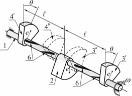
a) General view
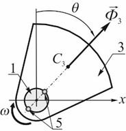
b) Moving unbalance
When the unbalanced shaft rotates, each of the unbalances generates a corresponding centrifugal force of inertia:
At start-up, both movable unbalanced masses are located at their initial positions 3″ and 4″, diametrically opposite to the fixed unbalanced mass , thereby ensuring the dynamic balance of the UVV-6 vibration exciter. In this configuration, the forces , and are collinear, while the forces and act in directions opposite to that of the force . As a result, the resultant vector of the inertial forces is:
After the drive motor reaches its operating angular speed, the unbalanced masses 3 and 4 are actuated by the control mechanism. Since the helical grooves 6 on the left- and right-hand sections of the shaft 1 have opposite directions of helix, simultaneous displacement of the movable unbalanced masses in opposite directions from their initial positions 3″ and 4″ causes them to rotate synchronously in the same direction relative to these positions.
The dynamic action generated by the CMCUVE UVV-6 at the instant when the movable unbalanced masses have rotated through an angle from their initial positions 3″ and 4″, while being located at a distance from the fixed unbalanced mass at positions 3′ and 4′, respectively, is determined. For this purpose, the force diagram shown in Fig. 2 is considered.
Resolving the forces and into their orthogonal components, as shown in Fig. 2(a), yields a new system of five forces that is equivalent to the original force system . Since, for any position of the unbalanced shaft 1, the forces , and are collinear, while the forces and always act in directions opposite to that of the force , the magnitude of the resultant of these three forces is:
Fig. 2Power scheme of CMCUVE UVV-6
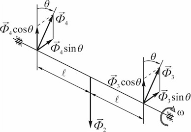
a)
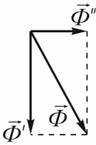
b)
The other two forces and are also collinear and have the same direction, so their resultant is:
Since at any moment of time the forces and are located at right angles to each other (Fig. 2(b)), their resultant is determined by the Pythagorean theorem:
and after simple mathematical transformations it takes the form:
Thus, the UVV-6 vibration exciter generates an excitation force whose magnitude is determined by Eq. (7).
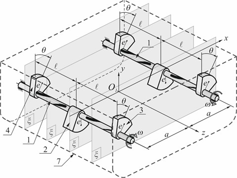
The design of the investigated controlled mechanical exciter of circular translational vibrations comprises two UVV-6 vibration exciters mounted in a housing 5, as shown in Fig. 3.
Fig. 3Unbalanced exciter of circular translational vibrations: 1 – unbalance shaft; 2 – fixed unbalance; 3, 4 – movable unbalances; 5 – housing
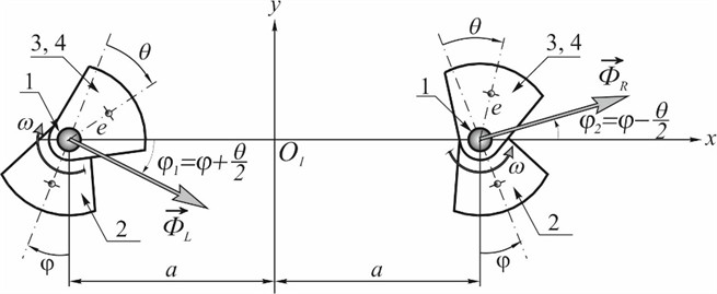
Analyzing the calculation scheme shown in Fig. 4, it can readily be established that the projection of the excitation force generated by the considered vibration exciter onto the -axis is zero, whereas its projections onto the - and -axes are given by the following expressions:
where is the angle defining the position of the fixed unbalanced mass 2, measured from its initial position, and is the angular velocity of each of the shafts 1 under operating conditions.
The obtained expressions show that, depending on the rotation angle of the movable unbalanced masses, the horizontal component of the excitation force varies according to the law , whereas the vertical component varies according to the law . It follows that, at (when ), the component reaches its maximum value, while the component is equal to one-half of its maximum value at this instant. When , the vertical component reaches its maximum value, whereas the horizontal component is equal to zero.
A distinctive feature of this design is that, despite the absence of a resultant moment on each of the shafts 1 and 2, a moment about the -axis of the vibration exciter is generated by the resultant vectors of the inertial forces:
which causes the working member of the machine to oscillate about the specified axis with a phase lag of relative to the phases of and .
Fig. 4Design diagram of the exciter of directed circular vibrations
An important condition for the design of such a vibration exciter is to ensure fixed (rigid) synchronization of the rotation of the unbalanced shafts 1 and 2, with equal angular velocities and identical phases of deviation of the fixed unbalanced masses from the lower vertical position. Such synchronization can be achieved, for example, by means of spur gears.
4. Conclusions
The obtained Eqs. (2-4) constitute a mathematical model of the dynamic action of the controlled mechanical exciter of circular translational vibrations. A straightforward mechanical and mathematical analysis of these equations leads to the following conclusion: the resultant dynamic action of the considered vibration exciter causes the material elements of the processed medium to move within parallel planes perpendicular to the -axis, which are schematically designated as in Fig. 3. Depending on the values assigned to the parameters and/or , the material elements of the processed medium move within these planes along circular or elliptical trajectories. This property of the vibration exciter makes it possible to modify its dynamic action when required, thereby meeting specific technological requirements.
References
-
S. Schiller, D. Perchtold, and W. Steiner, “Nonlinear and chaotic dynamics of a vibratory conveying system,” Nonlinear Dynamics, Vol. 111, No. 11, pp. 9799–9814, Mar. 2023, https://doi.org/10.1007/s11071-023-08363-4
-
S. Schiller, W. Steiner, and M. Schagerl, “Extension of the bouncing ball model to a vibratory conveying system,” Nonlinear Dynamics, Vol. 111, No. 21, pp. 19685–19702, Sep. 2023, https://doi.org/10.1007/s11071-023-08911-y
-
C. Duan et al., “Variable elliptical vibrating screen: particles kinematics and industrial application,” International Journal of Mining Science and Technology, Vol. 31, No. 6, pp. 1013–1022, Aug. 2021, https://doi.org/10.1016/j.ijmst.2021.07.006
-
B. Chen, B. Wang, J. Yan, and J. Han, “Optimization research on screening parameters of elliptical vibrating screen based on DEM theory,” Proceedings of the Institution of Mechanical Engineers, Part E: Journal of Process Mechanical Engineering, Vol. 236, No. 5, pp. 1992–2000, Feb. 2022, https://doi.org/10.1177/09544089221078388
-
V. Gurskyi, V. Korendiy, P. Krot, R. Zimroz, O. Kachur, and N. Maherus, “On the dynamics of an enhanced coaxial inertial exciter for vibratory machines,” Machines, Vol. 11, No. 1, p. 97, Jan. 2023, https://doi.org/10.3390/machines11010097
-
V. Korendiy, V. Gursky, O. Kachur, P. Dmyterko, O. Kotsiumbas, and O. Havrylchenko, “Mathematical model and motion analysis of a wheeled vibro-impact locomotion system,” Vibroengineering Procedia, Vol. 41, pp. 77–83, Apr. 2022, https://doi.org/10.21595/vp.2022.22422
-
V. Korendiy, O. Parashchyn, O. Kotsiumbas, R. Palash, O. Levytska-Revutska, and O. Hrytsun, “Simulation of motion trajectories and kinematic characteristics of an oscillatory system with a planetary-type vibration exciter,” Vibroengineering Procedia, Vol. 58, pp. 31–38, May 2025, https://doi.org/10.21595/vp.2025.24973
-
V. Korendiy, O. Parashchyn, O. Kachur, V. Lozynskyi, S. Hrevtsov, and N. Hembara, “Trajectory-oriented synthesis of a planetary-type vibration exciter for vibratory technological equipment,” Vibroengineering Procedia, Vol. 61, pp. 1–10, Apr. 2026, https://doi.org/10.21595/vp.2026.26348
-
V. Korendiy, O. Yaniv, R. Predko, I. Laushnyk, A. Dzyubyk, and S. Hrevtsov, “Trajectory-based synthesis of a three-mass vibratory system excited by a dual phase-controlled crank-slider mechanism,” Vibroengineering Procedia, Vol. 62, pp. 41–50, Jun. 2026, https://doi.org/10.21595/vp.2026.26165
-
S. Zhyhylii, M. Kharchenko, and J. Katella, “Mathematical model of the dynamic action of the controlled vibration exciter on the processed medium of mixer with toroidal working container,” International Journal of Engineering and Technology, Vol. 7, No. 3.2, pp. 478–485, 2018, https://doi.org/10.14419/ijet.v7i3.2.14576
-
L. Serdyuk, “The controlled vibromachines,” in Jubilee Scientific Conference. University of Architecture, Civil Engineering, and Geodesy, Sofia, pp. 43–48, 2007.
About this article

The authors have not disclosed any funding.
The datasets generated during and/or analyzed during the current study are available from the corresponding author on reasonable request.
The authors declare that they have no conflict of interest.

