Abstract
The paper presents an investigation into the operational strength of a vibratory separator equipped with a system of flat screens, a spring suspension, and two independently driven vibration exciters. A three-dimensional parametric model of the separator was developed using Autodesk Inventor Professional. Based on this model, parametric optimization of the separator body was performed, followed by modal analysis to determine the natural frequencies of both the vibrating body and the welded supporting frame. Structural deformations under the applied operating loads were evaluated, and the factor of safety was determined for the entire separator body. Furthermore, the structural integrity of the welded supporting frame was verified. The obtained results confirm the suitability of the proposed design in terms of operational strength and provide recommendations for optimizing the structural parameters of future physical prototypes. The proposed methodology can be extended to the design and structural analysis of other types of vibratory machines.
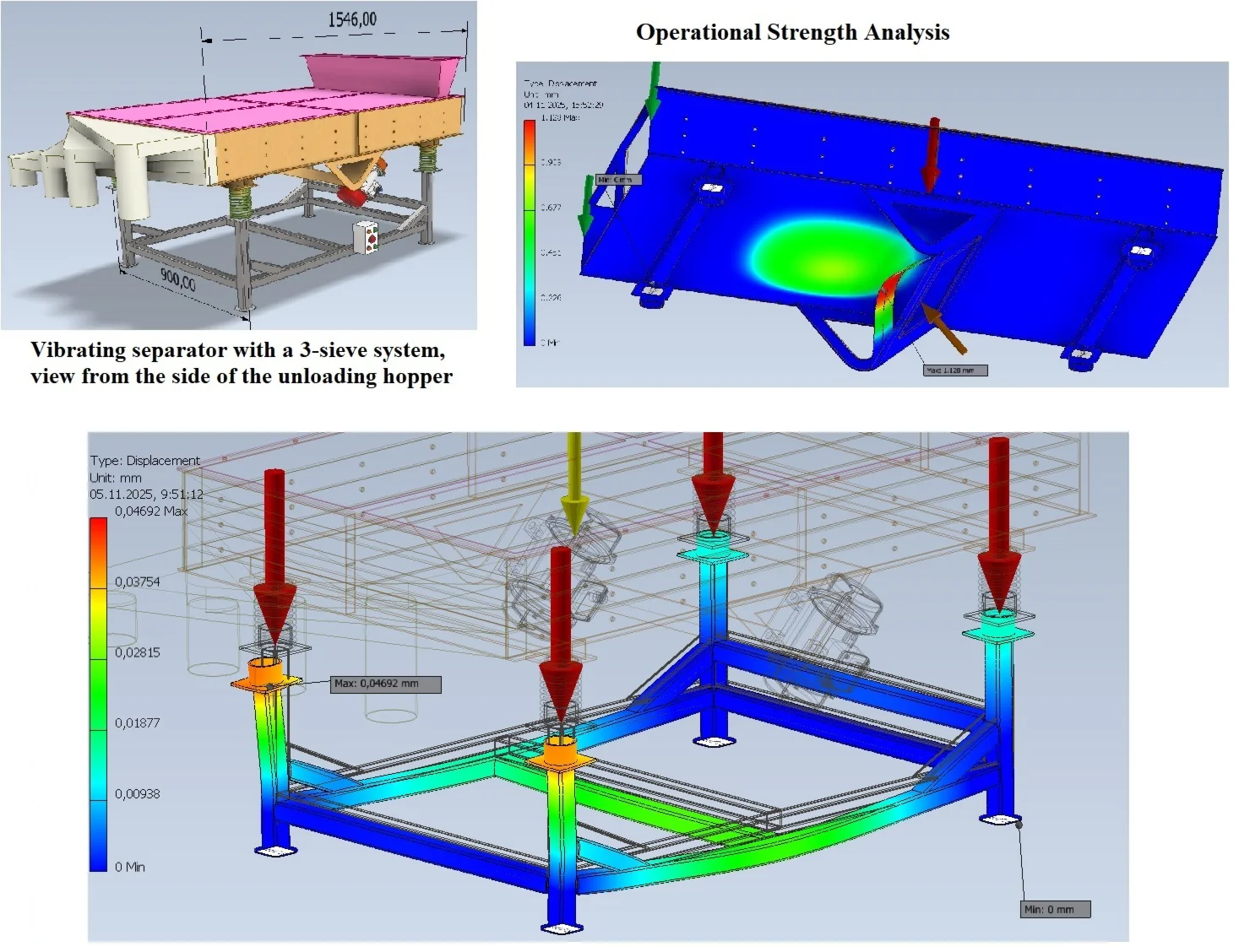
Highlights
- Modern CAD/CAE systems quickly and efficiently perform such a calculation based on the created three-dimensional model of vibratory separator.
- A modal analysis was also performed for the vibrating body of separator to determine the frequencies of its natural oscillations.
- The reactive forces applied to the frame are the ties from the foundation, on which the four legs of the frame stand.
- Based on three-dimensional parametric model, parametric optimization of the separator body was performed, followed by modal analysis to determine the natural frequencies of both the vibrating body and the welded supporting frame.
- The obtained results confirm the suitability of the proposed design of vibratory separator in terms of operational strength and provide recommendations for optimizing the structural parameters of future physical prototypes.
1. Introduction
The development of various industries requires the creation of new equipment models and the modernization of existing ones. This also applies to vibration separators, which are widely used in production. Accordingly, the creation of a new model requires a test of operational strength to determine whether the equipment will withstand operational loads. In the case of creating a parameterized three-dimensional model of a vibration separator, such a calculation is extremely important. This is due to the fact that it is impossible to take into account all the subtleties of the design when automatically changing its dimensions. If the parameters are set incorrectly, two consequences are possible: the model will not withstand operational loads or the model will withstand the load but will be too metal-intensive and economically inexpedient.
Modern CAD/CAE systems quickly and efficiently perform such a calculation based on the created three-dimensional model. Also, such a calculation allows you to optimize the design and avoid unnecessary costs at the beginning of the prototype creation, which is extremely relevant in the production of new equipment.
Taking into account the above, based on the created parametric model of a vibrating separator with a flat sieve system, a test of operational strength was carried out in the Autodesk Inventor Professional system and recommendations were given for optimizing the design. The proposed method makes it possible to speed up and reduce the cost of manufacturing new vibrating separators.
Increasing the productivity and reliability of vibrating separators requires improving the methods of their mathematical modeling, studying the dynamics and assessing the stress-strain state of the structure.
Today, considerable attention is paid to the use of FEM and DEM analysis to prevent the development of fatigue damage to supporting elements. For example, in work [1] using DEM - modeling, the operation of a vibrating screen was studied and the influence of vibration parameters on the load distribution between the material and the screen surface was determined. Such results make it possible to further study the strength of the screen structure. A similar approach was used in [2] and [3] where multilayer and high-frequency screens are studied. However, the main attention here was paid to the optimization of the technological process, and the issues of the durability of the separator elements remained insufficiently covered. The study of the interaction of bulk material with the working bodies of the vibrating separator [4, 5] allows us to determine the contact loads that can be used as initial data when calculating the stress-strain state of the structure.
A significant development of the analysis of operational strength is presented in the works [6-8], where the results of modeling and determination of fatigue life are combined, which will allow predicting the residual resource of the equipment structure. Also, in [9], the loads acting on the sieve panels of vibrating separators and the influence of design parameters on the level of stresses in the machine elements were investigated. Mathematical modeling of a vibrating separator [10, 11] allows for timely detection of structural defects, but also does not contain a comprehensive analysis of the stress-strain state of the supporting elements. Also, mathematical modeling of vibrating machines was carried out in [12-14]. Here, on its basis, the influence of the structural parameters of the equipment and the amplitude of the frequency characteristics of their working bodies on the efficiency of the movement of loose materials was investigated. The issue of the stress-strain state of the working bodies of vibrating machines was also not considered in this case.
Studies of operational machines using the finite element method [15, 16] allow us to identify critical stress concentration zones, which allows us to adjust the design of the vibrating separator and increase its durability. However, these works analyze only individual structural components of the separators. Therefore, a comprehensive study of the strength of the vibration separator is relevant for modern developments.
2. Main material
The three-dimensional parameterized model of a vibrating separator with a system of flat screens is presented in Fig. 1. The vibrating body of the separator is taken as the main unit. The loading and unloading hoppers are attached to it, and the body itself is located on a frame with a spring suspension. The body is driven by two independent drives.
The wall thickness of the support profile is assumed to be 3 mm, the wall thickness of the engine mounting system is 5 mm, etc. With such thicknesses, the body mass was 71 kg. The calculation of the strength of such a body using Autodesk Inventor showed that with such wall thicknesses, the minimum safety factor was 6.15. The obtained value is relatively high. It indicates that the body is too metal-intensive. When calculating the body, active and reactive forces were applied to it. Active forces: the force of the body’s own weight; force from the action of the system of three sieves with loading – 825 N per sieve support (750/2 N from loading and 900/2 N from the weight of the sieves); force of impact of the top cover with the loading hopper and the mixture in it – 750 N; force of the own weight of the drive vibration motors – 350 N; force of impact of the unloading hopper with fractions – 200 N. The reactive forces applied to the housing will be the forces of the suspension springs applied to their fastening system in the lower part of the housing. Air resistance and ambient temperature are neglected due to the insignificance of their influence.
Parametric optimization of the vibrating body was carried out by selecting the thickness of the body wall and the thickness of the support profile of the spring fastening system to the body. (Fig. 1). Optimization criteria: the minimum safety factor should be at least 2.5 and the body mass should not exceed 45 kg. The body wall thickness varied from 1.5 to 2.25 mm in increments of 0.25 mm. The support wall thickness varied from 2 to 2.75 mm also in increments of 0.25 mm.
Fig. 1Vibrating separator with a 3-sieve system, view from the side of the unloading hopper
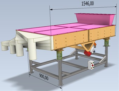
Fig. 2Physical parameters of the vibrating separator housing before and after its parametric optimization
From the results of the substitution, with a body wall thickness of 1.5 mm, regardless of the support wall thickness, the condition for the minimum safety factor was not met – it was less than 2.5, although the mass condition was met (it was less than 45 kg). With a case wall thickness of 1.75 mm and a support wall thickness of 2 mm, 2.25 mm and 2.5 mm – the condition for the safety factor was also not met, although the mass condition was met (it was less than 45 kg). But with a support wall thickness of 2.75, two conditions were already met: the safety factor was 2.65, and the body mass was 43.928 kg – it was less than 45 kg. The next step of the research (case wall thickness – 2 mm, support wall thickness – 2 mm) showed that the condition for the body mass was not met – it exceeded 47 kg. Thus, the optimal parameters for the body were: a body wall thickness of 1.75 mm (and accordingly all its flanges) instead of the original 3 mm; a support wall thickness of 2.75 mm instead of the original 3 mm. This made it possible to reduce the mass of the hull from 71.064 kg to 43.928 kg (Fig. 2), i.e. by 27.136 kg, or 1.618 times, while maintaining its operational strength.
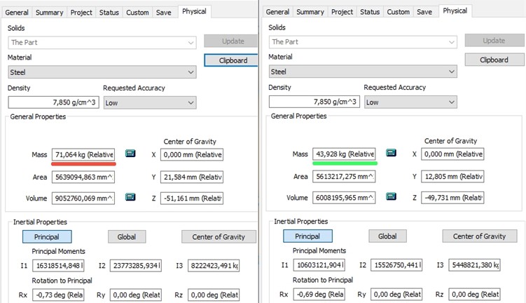
The calculated wall thicknesses are included in the final model of the vibrating separator. Fig. 3 shows the distribution of deformations from applied loads over the volume of the vibrating body of the vibrating separator. The hull model contains 149.285 nodes and 73.766 elements. The frame model contains 200.967 nodes and 99.337 elements. Mesh parameters for the working body: grading factor – 1.500, minimum element size – 0.200, maximum turn angle – 60 degrees.
The material type and parameters are presented in Table 1.
Fig. 3Distribution of deformations from applied loads over the volume of the vibrating body of the vibrating separator
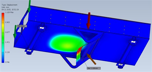
Table 1Material type and parameters
Name | Steel | |
General | Mass density | 7.85 g/cm3 |
Yield strength | 207 MPa | |
Ultimate tensile strength | 345 MPa | |
Stress | Young’s modulus | 210 GPa |
Poisson’s ratio | 0.3 ul | |
Shear modulus | 80.7692 GPa | |
From the research results, the maximum stress of 78.07 MPa and the minimum safety factor of 2.65 are observed in the upper part of the suspension spring mounting support. The maximum displacement of 1.128 mm is located in the central part of the bottom of the drive vibration motor mounting support (Fig. 3.)
A modal analysis was also performed for the vibrating body to determine the frequencies of its natural oscillations. 8 fundamental frequencies were determined. Such a study is necessary in order to establish whether the vibrating body may enter resonance during its operation. Since the number of revolutions of the drive vibration motors is 750 rpm, the frequency of the separator disturbance by the drive is 12.5 Hz. The minimum value of the natural oscillation frequency of the body is 21.72 Hz. It is 1.74 times greater than the disturbance frequency. Thus, from the conducted study, we conclude that the vibrating body operates in the pre-resonant zone, and the occurrence of resonance in the body during the operation of the separator is unlikely. Fig. 4. shows the results of modal analysis at a natural frequency of 45.01 Hz.
Based on the above, the initial model of the vibrating separator withstands operational loads.
Further, the work tested the operational strength of the welded structure of the supporting frame of the vibrating separator with a system of flat screens for the initial design variant in (Fig. 1) The frame is made of ISO 12633-2 40×40×3 profile in the form of a hollow square tube. The load on the frame comes from the suspension springs in four places with a value of 93.75 kg or 937.5N from one spring during the operation of the separator. Another active force acting on the frame is the force of its own weight. The reactive forces applied to the frame are the ties from the foundation, on which the four legs of the frame stand.
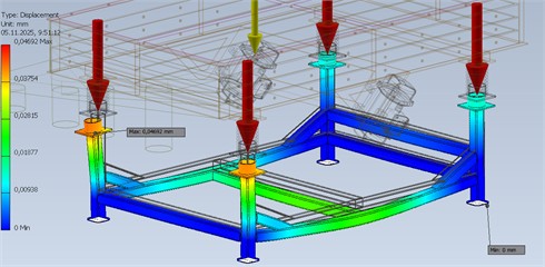
Fig. 5 shows the deformations from the applied loads over the volume of the welded structure of the supporting frame of the vibrating separator with a system of flat screens. From the obtained research results, the maximum stress of 50.3 MPa and the minimum safety factor of 4.12 are observed in the lower part of the frame leg on the side of the unloading hopper. The maximum displacement of 0.04692 mm is located in the upper part of this leg at the location of the suspension spring attachment.
Fig. 4Results of modal analysis of the vibrating body at a frequency of 45.01 Hz
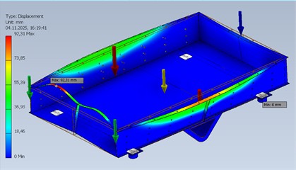
Fig. 5Distribution of deformations from applied loads over the volume of the welded structure of the supporting frame
For the welded structure of the supporting frame, a modal analysis was also conducted to determine the frequencies of its natural vibrations. 8 fundamental frequencies were determined. Such a study is necessary in order to establish whether it is possible for the welded structure of the supporting frame to enter resonance during the operation of the separator. Since the number of revolutions of the drive vibration motors is 750 rpm, the frequency of the separator disturbance by the drive is 12.5 Hz. The minimum value of the natural frequency of the frame oscillations is 109.31 Hz. It is 8.745 times greater than the disturbance frequency. Thus, from the study conducted, we conclude that the frame operates in the pre-resonance zone, and the occurrence of resonance in it during the operation of the separator is unlikely. Fig. 6 shows the results of the modal analysis at a natural frequency of 161.03 Hz.
Fig. 6Results of modal analysis of the separator frame at a frequency of 161.03 Hz
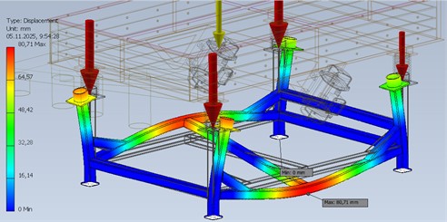
Table 2 presents the parameters of the vibrating body before and after optimization.
Table 2Physical properties for vibrating body
General properties | Before optimization | After optimization |
Material | Steel | Steel |
Density | 7,850 g/cm3 | 7,850 g/cm3 |
Mass | 71,064 kg (Relative Error = 0,123834 %) | 43,928 kg (Relative Error = 0,104327 %) |
Area | 5639094,863 mm2 (Relative Error = 0,000000 %) | 5613217,275 mm2 (Relative Error = 0,000000 %) |
Volume | 9052760,069 mm3 (Relative Error = 0,123834 %) | 6008195,965 mm3 (Relative Error = 0,104327 %) |
3. Conclusions
Based on the presented calculation, it is recommended to reduce the wall thickness in the initial model without affecting the structural strength. The optimal parameters for the housing were: the thickness of the housing wall is 1.75 mm (and accordingly all its flanges) instead of the original 3 mm; the thickness of the support wall is 2.75 mm instead of the original 3 mm. This made it possible to reduce the mass of the housing from 71.064 kg to 43.928 kg, i.e. by 27.136 kg, or 1.618 times while maintaining its operational strength. The calculated wall thicknesses are included in the final model of the separator housing. As can be seen from the obtained research results, the maximum stress of 78.07 MPa and the minimum safety factor of 2.65 are observed in the upper part of the support for mounting the suspension springs. The maximum displacement of 1.128 mm is observed in the central part of the bottom of the support for mounting the drive vibration motors.
The calculation method used makes it possible to verify the model of the vibrating separator, optimize it at the design stage, and provide recommendations regarding design parameters. These calculations can be used for other models of vibrating machines.
References
-
Z. Chen, X. Tong, and Z. Li, “Numerical investigation on the sieving performance of elliptical vibrating screen,” Processes, Vol. 8, No. 9, p. 1151, Sep. 2020, https://doi.org/10.3390/pr8091151
-
H. Yan, Y. Li, F. Yuan, F. Peng, X. Yang, and X. Hou, “Analysis of the screening accuracy of a linear vibrating screen with a multi-layer screen mesh,” Strojniški Vestnik – Journal of Mechanical Engineering, Vol. 66, No. 5, pp. 289–299, 2020, https://doi.org/10.5545/sv-jme.2019.6523
-
B. Chen et al., “Multi-parameter optimization of high-frequency vibrating screen based on DEM,” Chinese Journal of Engineering, Vol. 43, No. 6, pp. 852–861, 2021.
-
N. Xo and N. K. Linh, “Applications of discrete element method (DEM) in modeling the impact of dynamic and technological parameters on the material movement on the vibrating screen surface,” IOP Conference Series: Materials Science and Engineering, Vol. 843, No. 1, p. 012024, May 2020, https://doi.org/10.1088/1757-899x/843/1/012024
-
V. Korendiy, V. Zakharov, V. Gurey, P. Dmyterko, I. Novitskyi, and O. Havrylchenko, “Modelling the operation of vibratory machine for single-sided lapping of flat surfaces,” Vibroengineering Procedia, Vol. 38, pp. 1–6, Jun. 2021, https://doi.org/10.21595/vp.2021.22001
-
T. M. Lenkovskiy et al., “An effective crack tip region finite element sub-model for fracture mechanics analysis,” Archives of Materials Science and Engineering, Vol. 87, No. 2, pp. 56–65, 2017, https://doi.org/10.5604/01.3001.0010.7446
-
F. Yan, H. Lu, and L. Xiao, “Fatigue life prediction of cracked cross beam of mining linear vibrating screen under cyclic load,” Scientific Reports, Vol. 14, No. 1, Aug. 2024, https://doi.org/10.1038/s41598-024-70671-5
-
O. M. Stankevych, “Methods of artificial intelligence for acoustic emission diagnostics of fracture stages (A review). P. 1: Algorithms of unsupervised and supervised machine learning,” Physicochemical Mechanics of Materials, Vol. 60, No. 3, pp. 5–14, 2024, https://doi.org/10.15407/pcmm2024.03.005
-
Z. Zhang, J. Tang, and X. Xiong, “Load characteristics of screen panels in vibrating flip-flow screens,” Mechanics Based Design of Structures and Machines, Vol. 52, No. 12, pp. 10363–10388, Dec. 2024, https://doi.org/10.1080/15397734.2024.2355596
-
P. Krot et al., “Development and verification of the diagnostic model of the sieving screen,” Shock and Vibration, Vol. 2020, pp. 1–14, Jun. 2020, https://doi.org/10.1155/2020/8015465
-
D. Rebot, V. Topilnytskyy, R. Kovalchuk, Z. Odosii, and I. Taras, “Modeling the dynamics and design of a vibrating separator with an unbalanced drive and pendulum suspension,” in Lecture Notes in Mechanical Engineering, Cham: Springer Nature Switzerland, 2026, pp. 62–73, https://doi.org/10.1007/978-3-032-14926-8_6
-
V. Gursky, I. Kuzio, and V. Korendiy, “Optimal synthesis and implementation of resonant vibratory systems,” Universal Journal of Mechanical Engineering, Vol. 6, No. 2, pp. 38–46, Aug. 2018, https://doi.org/10.13189/ujme.2018.060202
-
O. Kachur, V. Korendiy, O. Lanets, R. Kachmar, I. Nazar, and V. Heletiy, “Dynamics of a vibratory screening conveyor equipped with a controllable centrifugal exciter,” Vibroengineering Procedia, Vol. 48, pp. 8–14, Feb. 2023, https://doi.org/10.21595/vp.2023.23175
-
V. Korendiy, O. Kachur, I. Hurey, R. Predko, R. Palash, and O. Havrylchenko, “Modelling and experimental investigation of the vibratory conveyor operating conditions,” Vibroengineering Procedia, Vol. 47, pp. 1–7, Dec. 2022, https://doi.org/10.21595/vp.2022.23057
-
B. Ramatsetse, K. Mpofu, and O. Makinde, “Failure and sensitivity analysis of a reconfigurable vibrating screen using finite element analysis,” Case Studies in Engineering Failure Analysis, Vol. 9, pp. 40–51, Jun. 2017, https://doi.org/10.1016/j.csefa.2017.04.001
-
Y. J. Hou, P. Fang, and L. Zeng, “Finite element analysis of dual-frequency vibrating screen,” Advanced Materials Research, Vol. 479-481, pp. 2124–2128, Feb. 2012, https://doi.org/10.4028/www.scientific.net/amr.479-481.2124
About this article

The authors have not disclosed any funding.
The datasets generated during and/or analyzed during the current study are available from the corresponding author on reasonable request.
The authors declare that they have no conflict of interest.

