Abstract
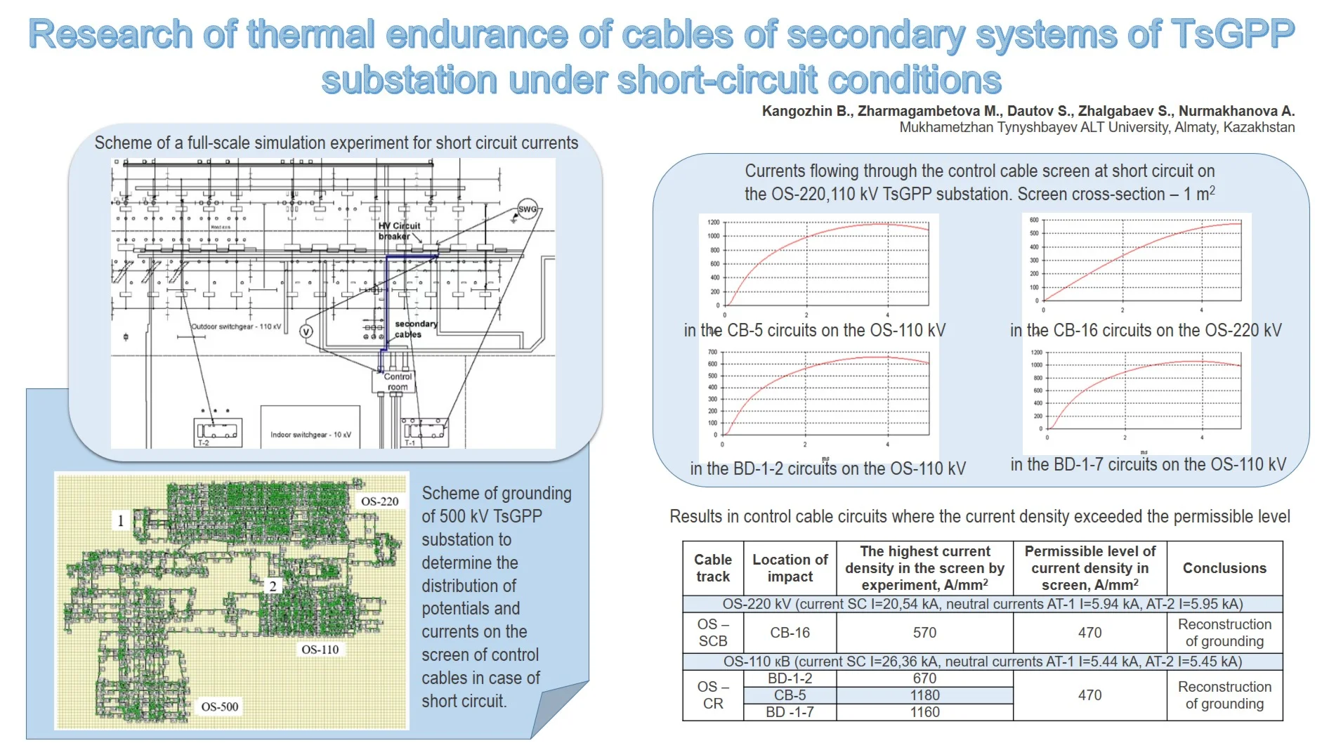
The article presents the results of research on thermal endurance of control cables of secondary systems of substation 500 kV “TsGPP” substation under single-phase short circuits (SC). The study is based on the combination of field experiments and numerical modeling of the computational model of the grounding, which determines the distribution of potentials on the grounding and currents on the cable shields. The results showed that when a short-circuit occurs on the OS (Outdoor Switchgear)-220 kV and OS-110 kV current density flowing through the screen may exceed the permissible values, which leads to thermal damage to cables and, as a result, an increased risk of damage to the secondary relay protection and control systems. Based on the analysis of the obtained data, recommendations for optimizing the configuration of the grounding have been proposed. Densification of local grounding and an increase in the number of connections between the shield grounding and the grounding grid leads to a reduction in the potential distribution gradient in the grounding circuit of the “TsGPP” substation. Given the soil resistivity parameters specific to the substation under study, the current levels flowing through the control cable screens have been reduced to values below the established permissible thresholds. For the first time, the results of research conducted at an actual high-voltage substation have demonstrated the feasibility of ensuring the thermal stability of control cables through the reconstruction of the grounding.
Highlights
- Field experiments and modeling at the TsGPP substation identified critical points where control cable screens exceed thermal endurance during short-circuit events
- Optimizing grounding configuration by densifying local grounding and increasing shield-to-grid connections effectively reduces current density in control cable screens
- Implementing grounding improvements ensures thermal endurance of control cables, enhances relay protection reliability, and reduces the risk of large-scale power outages
1. Introduction
The reliable functioning of the electric power system (EPS) is determined by the correct operation of relay protection and automation (RPA) and compliance with electromagnetic compatibility (EMC) standards for secondary equipment of control, automation and protection systems involved in electrical networks. At the same time, information is transmitted between control, automation and protection systems via secondary circuits using control cables.
During operation, various emergency situations may occur in the EPS, leading to large-scale outages. The analysis shows that short circuits are the root cause of many major accidents. They account for about 20-30 % of all EPS damage [1].
In October 2023, the emergency power outage in Astana city was caused by a single-phase short-circuit, as a result of a cracked headband of the bypass busbar disconnector, which broke off from the column and fell to the ground, resulting in thermal damage to the control cable and voltage extraction cabinet. As a result, two lines adjacent to the ACHP-2 thermal power plant were disconnected, which led to a reduction of generation capacity at ACHP-2 from 530 MW to 120 MW, causing a large-scale blackout in the city. The complete restoration of the power supply took several hours [2].
This accident demonstrates how local damage can escalate into a cascading accident leading to a system blackout. If the secondary systems are not protected from external electromagnetic interference, then a local accident can lead to multiple outages and huge socio-economic losses.
In connection with the above, it is relevant to study the thermal endurance of control cables during SC.
To reduce electromagnetic interference, shielded control cables, which are grounded on both sides, are used. However, this raises a further problem related to ensuring the thermal endurance of the control cable shield. This problem arises due to the nonequipotency of the grounding during SC.
Fig. 1The grounded shielded control cable at the TsGPP substation
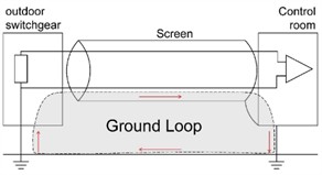
During the SC, the current flowing through the equipment and the grounding will increase the potential at the grounding conductor. At the same time, the potential on the screens of the control cables will also increase, but of varying magnitude due to the length of the control cables. Thus, a certain amount of current will flow through the screen, which can lead to a violation of the thermal endurance of the cables. The thermal endurance of control cables is assumed to be the flow of currents through the screen, at which the cable does not heat up above the permissible values according to Eq. (1):
where, – the current flowing through the screen at SC, A; – permissible current, A.
This research will consider the thermal endurance of control cables with single-phase short circuits that occur in control system circuits due to potential differences on the screens through inductive coupling and coupling through total resistance.
The scientific contribution of this study is the investigation of the thermal endurance of relay protection of control cables at an actual high-voltage electrical substation, taking into account the characteristic dimensions of its grounding. For the first time, it has been demonstrated that under soil conditions typical for the Republic of Kazakhstan, thermal endurance of control cables can be achieved by mitigating the potential gradient across the substation’s grounding system.
2. Methodology
Analysis of various approaches to studying cable thermal endurance, presented in [3]-[5], shows that in modern practice two main methods are most often used: field studies and modeling in specialized software.
In [4], field experiments were conducted by an artificial single-phase SC. During the experiment, the authors measured the potential difference on the grounding grid and proposed a way to reduce the potential on secondary cables by “sealing” the grounding.
Also, the authors in [5] conducted a comparative analysis of the thermal endurance of OPGW cables using the finite element method (FEM) in a two-dimensional (2D) model to analyze heat losses in cables. However, unlike numerical methods, our measurements are carried out directly at the TsGPP substation, which allows us to take into account the condition of the contact connections, the configuration of the grounding and the topology of laying control cables.
At the same time, unlike [3], it is necessary to give priority to minimizing the impact of experiments on the technological process of the substation and to simulate real SC current in the software. These requirements are provided by the methodology [6], which was applied in our studies of the thermal stability of control cables.
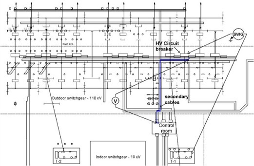
To determine the possible levels of voltages and currents affecting the cables of RP and technological control systems during a single-phase SC ground fault, measurements of potential distribution and currents on the grounding during the simulation of a single-phase SC ground fault are carried out. The measurements use KDZ-1 (a measuring complex for diagnosing the quality of grounding circuits). The scheme of such measurements is shown in Fig. 2. The detailed sequence of measurements is given in [6].
Fig. 2Scheme of a full-scale simulation experiment for SC currents
The measurement results are recalculated to real SC currents using the ORU-M program “Modeling of grounding with a multilevel structure”. The obtained data on the currents flowing through the control cables screen is compared with the permissible value of the thermal endurance of the control cables according to Eq. (2). The time of operation of the backup protection was taken as the time of the SC current flow. Based on this, it is possible to determine the dependence of the permissible screen current density on the SC current flow time:
where, – permissible overheating of the control cable NYCY, = 130 ℃; – current flow time, s; – resistivity of the screen material at 30 ℃, Ohm∙m.
The ambient temperature is taken as the initial temperature, equal to 30 ℃. At the TsGPP substation, NYCY brand cables are used as control cables, which, according to their specifications, the permissible cable temperature in case of a SC is 160 ℃. The response time of the backup protection was taken as the time of the SC current flow through the control cable screens.
Due to the fact that many control cables of different cross-sections are used at the substation, the current density of the control cables flowing through the screen was used as a parameter of thermal endurance.
3. Results
Fig. 3 shows a simulation model of the grounding system for the 500 kV “TsGPP” substation, developed using the “ORU-M” software.
Fig. 3Scheme of grounding of 500 kV TsGPP substation to determine the distribution of potentials and currents on the screen of control cables in case of SC. 1 – SCB (Substation Control Building), 2 – CR-110 kV (control room)
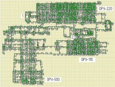
In the simulation model, the grounding electrodes are represented as solid cylindrical steel conductors with a diameter of 14 mm. At the substation, the control‐cable screens are tape‐type; accordingly, in the model the screen is simulated as a cylindrical copper conductor. For calculation convenience, the screen’s cross‐sectional area was set to 1 mm2.
The short-circuit current parameters for each OS vary (see Table 1) and correspond to the single-phase SC currents and their components provided by the RPA service of the TsGPP substation.
The reliability of the model was confirmed by conducting field simulation experiments directly at the substation [7].
By simulating a SC for each equipment in the computational model of the grounding, control cables were identified on which current densities exceeding the permissible value of the thermal endurance of the control cable flow through the screens, causing its thermal damage (see Fig. 4).
Table 1 shows the results in control cable circuits where the current density exceeded the permissible level.
Table 1Industrial frequency interference in secondary circuit breaker cables
Cable track | Location of impact | The highest current density in the screen by experiment, A/mm2 | Permissible level of current density in the screen, A/mm2 | Conclusions |
OS-220 kV (current SC 20,54 kA, neutral currents AT-1 5.94 kA, AT-2 5.95 kA) | ||||
OS-SCB | CB-16 | 570 | 470 | Reconstruction of grounding |
OS-110 кВ (current SC 26,36 kA, neutral currents AT-1 5.44 kA, AT-2 5.45 kA) | ||||
OS-CR | BD-1-2 | 670 | 470 | Reconstruction of grounding |
CB-5 | 1180 | |||
BD -1-7 | 1160 | |||
According to the results of modeling also obtained diagrams of potency distribution on OS –220 and OS – 110 kV (see Fig. 5).
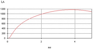
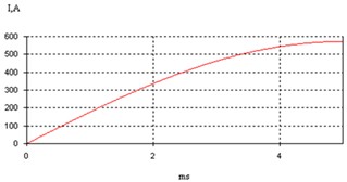
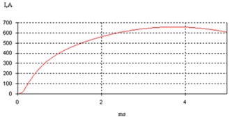
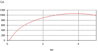
Fig. 4Currents flowing through the control cable screen at SC on the OS-110 kV TsGPP substation. Screen cross-section – 1 m2
a) In the CB-5 circuits on the OS-110 kV
b) In the CB-16 circuits on the OS-220 kV
c) In the BD-1-2 circuits on the OS-110 kV
d) In the DB-1-7 circuits on the OS-110 kV
Fig. 5Potential distribution diagram in case of SC at the TSGPP substation
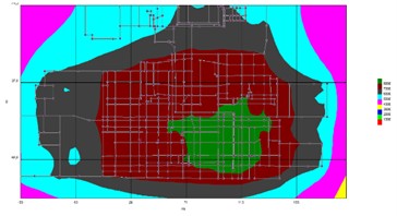
a) CB-3 at OS-110 kV
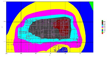
b) KS-2 at OS-220 kV
4. Discussion
As can be seen from Table 1, the data obtained indicate that a high-temperature hazard may occur in the secondary circuits on the OS -220 and 110 kV control cables due to the lack of thermal endurance during SC.
Thus, according to the results of the study, characteristic places were identified on the OS-220 and OS-110 kV, where thermal endurance was not observed. These are:
– Control cables of equipment that has few connections to the SCB (CR).
– The equipment is located closest to the SCB (CR).
To ensure the thermal endurance of the control cables, it is necessary to equalize the potential that occurs (see Fig. 5) in the battery at SC. It is necessary to strengthen the local grounding at the grounding points of the control cable screens in the control unit. Experimental studies described in [8] confirm that optimization of the storage circuit makes it possible to reduce the thermal heating of control cables.
According to the authors, to ensure thermal endurance it is necessary to optimize the storage network by sealing local storage devices, as well as increasing the number of connections between the grounding point of the shield and the SCB (CR) by laying additional horizontal grounding.
Restrictions on the number of pages due to the requirements of the scientific conference do not allow us to consider in more detail various approaches to ensuring the thermal endurance of control cables.
The data obtained as a result of the field simulation experiment and modeling also indicate that the influence of currents and voltages on the screens of control cables is not taken into account when designing the grounding circuit. The existing regulatory and technical documentation on the organization of grounding in [9-11]. It does not take into account the thermal endurance of the control cable.
5. Conclusions
The current densities flowing through the screens of the control cables in the circuits of the ASTC (automated system of technological control) 500 kV TsGPP substation, caused by a rise of potential on the grounded screens of the control cables at short circuit on the OS-220 kV and OS-110 kV, exceed the permissible values.
The key factor influencing the value of the current density flowing through the screen at short circuit is the potential distribution over the grounding. Thus, the authors propose the organization of sealing of local grounding, as well as increasing the number of connections between the grounding point of the shield and the SCB (CB) in order to reduce the potential on the grounding conductor and reduce the currents flowing through the screens of control cables.
During the reconstruction or new design of the power facility, it is necessary to perform the storage taking into account the thermal endurance of the ASTC circuits. Thus, in order to ensure thermal endurance at substations, it is necessary to improve the contours of the grounding and take into account the criteria for electromagnetic compatibility. Compliance with these measures will reduce the risk of damage to the MP-RPA (microprocessor-based relay protection and automation) and minimize the threat of large-scale outages associated with thermal damage to the control cable in case of short circuits.
References
-
N. Sharma, A. Acharya, I. Jacob, S. Yamujala, V. Gupta, and R. Bhakar, “Major blackouts of the decade: underlying causes, recommendations and arising challenges,” in 9th IEEE International Conference on Power Systems (ICPS), pp. 1–6, Dec. 2021, https://doi.org/10.1109/icps52420.2021.9670166
-
“Annual Report of JSC “AREK” for 2023”, https://www.arek.kz/assets/files/otchet/go-2023.pdf.
-
B. R. Kangozhin, O. A. Baimuratov, M. S. Zharmagambetova, S. S. Dautov, and D. B. Kangozhin, “Noise immunity of devices of automated systems for technological control of energy facilities in the almaty region,” Studies in Systems, Decision and Control, Vol. 399, pp. 277–290, Dec. 2021, https://doi.org/10.1007/978-3-030-87675-3_17
-
Bo Zhang, Jinliang He, Yukuan Jiang, Qian Li, and Leishi Xiao, “Experimental research on interference in secondary cable from short-circuit current in substations,” in International Symposium on Lightning Protection (XIII SIPDA), pp. 137–140, Sep. 2015, https://doi.org/10.1109/sipda.2015.7339298
-
L. Gonzalez et al., “Electrical and thermal analysis of OPGW cables submitted to short circuit conditions,” in Proceedings of the 60th IWCS Conference, pp. 25–29, 2011.
-
“Determination of the electromagnetic environment and ensuring electromagnetic compatibility at electric power stations and substations,” Standard ST TOO-051140006727-01-2010. https://kitr.kz/page35541668.html.
-
“Report on the Research Work ‘Coordination of the Interference Immunity of SMART Devices of ASTS’ at the substation of JSC ‘KEGOC’: A Case Study of 500 kV ‘TsGPP’ substation, 500 kV ‘Shymkent’ substation, 220 kV ‘Kuibyshevskaya’ substation, and 220 kV ‘No.7’ substation,” 2024.
-
B. R. Kangozhin, S. S. Dautov, and T. M. Omarova, “Ensuring electromagnetic compatibility in the design of grounding for traction substations,” Bulletin of KazATC, Vol. 6, pp. 108–114, 2014.
-
“Electrical installations in buildings. Part 5. Selection and installation of electrical equipment. Chapter 54. Grounding devices and protective conductors.” GOST R 50571.10-96 (IEC 364-5-54-80), https://meganorm.ru/data2/1/4294850/4294850649.pdf
-
“Rules for Electrical Installations (with amendments and additions as of January 3, 2023),” PUE, Apr. 2025.
-
B. R. Kangozhin, S. S. Dautov, N. Izbasaruly, D. K. Kalashov, and A. T. Yegzekova, “Grounding device of a high-voltage substation to ensure electromagnetic compatibility,” Ministry of Justice of the Republic of Kazakhstan, Kazakhstan, Certificate of State Registration of Rights to the Copyrighted Work, Jul. 2017.
About this article

The authors have not disclosed any funding.
The datasets generated during and/or analyzed during the current study are available from the corresponding author on reasonable request.
The authors declare that they have no conflict of interest.
