Abstract
This paper presents a comparative analysis of the V.1 and V.2 versions of the Almaty Ankle Exoskeleton. The main objective of the study is to identify the structural and functional shortcomings observed in the first version (V.1) and to develop an improved prototype in the second version (V.2) by addressing these issues. The paper compares the kinematic schemes, CAD models, and physical prototypes of both versions, highlighting their structural differences and technical advancements. In addition, the results of a static structural analysis performed on the V.2 prototype using the Finite Element Analysis (FEA) method are presented. This analysis allowed for the evaluation of stress, strain, and displacement distribution within the structure. The results demonstrated that the exoskeleton can effectively handle applied loads, although additional reinforcement is required in certain critical regions. Overall, the findings provide a foundation for engineering solutions aimed at enhancing the functional performance of the ankle exoskeleton and its application in rehabilitation processes.
Highlights
- A comparative analysis of the V.1 and V.2 versions of the Almaty Ankle Exoskeleton was conducted to identify structural and functional limitations of the first prototype.
- An improved V.2 prototype was developed with a redesigned kinematic scheme and optimized CAD model for enhanced mobility.
- Finite Element Analysis (FEA) of V.2 showed sufficient structural strength and revealed critical areas that require reinforcement.
1. Introduction
In recent years, lower limb exoskeletons have gained significant importance in the fields of biomechanics and medical rehabilitation. These devices are designed to support human movement, assist muscle and joint function, and aid in the restoration and enhancement of motor capabilities. In particular, ankle exoskeletons play a vital role in the rehabilitation process following neurological and orthopedic conditions.
Ankle exoskeletons have attracted increasing interest in both scientific research and commercial applications [1-2]. Studies have shown that such devices can help restore balance after unexpected disturbances during walking [3]. From a commercial perspective, ankle exoskeletons are still in the early stages of development compared to other types of exoskeletons [4]. Furthermore, it has been demonstrated that powered ankle exoskeletons can reduce energy expenditure during military-relevant tasks in laboratory environments [5].
One of the most critical factors in the design of ankle exoskeletons is compliance with joint biomechanics. The exoskeleton must be sufficiently adaptable to accommodate the full range of ankle motion without restricting natural movement [6]. Moreover, these devices offer potential to reduce joint loading and enhance the effectiveness of rehabilitation [7]. The primary objective of such systems is to improve mobility and reduce the risk of injury in individuals with lower limb impairments [8-9].
The Almaty Ankle Exoskeleton project is a result of domestic research efforts in this direction. The main goal of the project is to develop an ankle exoskeleton that is functionally efficient, lightweight in structure, and user-friendly. This device is intended to support rehabilitation and enhance the mobility of individuals with impaired motor function.
The objective of this study is to analyze the structural and functional limitations identified in the first version (V.1) and propose an improved prototype in the second version (V.2). To this end, the evolution of the Almaty Ankle Exoskeleton, namely, the structural and functional differences between versions V.1 and V.2, is examined through comparative analysis.
The evolution of ankle exoskeleton technologies is currently a relevant topic in biomechanics and rehabilitation research. The comparative study of versions V.1 and V.2 demonstrates the technological development of the device in terms of improved mechanical design and functional performance. Furthermore, literature highlights the importance of structure-function relationships, energy harvesting potential, and quantum-optical support mechanisms in varying walking conditions (author, year).
These findings suggest that the advancement of exoskeleton technologies involves not only structural improvements but also the adaptation of functional capabilities to meet diverse rehabilitation needs. The development of exoskeletons with comprehensive rehabilitation functions remains a key research direction (author, year), reflecting a broader trend toward more universal and efficient assistive solutions.
Overall, the evolution of the Almaty Ankle Exoskeleton from version V.1 to V.2 represents a significant milestone in the development of wearable assistive technology. The introduced improvements have led to notable advancements in both structure and function. Future research will focus on further enhancing the rehabilitation effectiveness and adaptability of the device.
2. Comparative analysis of the kinematic scheme
The kinematic scheme is a fundamental component of the exoskeleton’s structural design, as it determines the device’s motion capabilities, degrees of freedom (DOF), and compatibility with human joint biomechanics. A properly constructed kinematic model ensures that the exoskeleton operates in accordance with biomechanical requirements, avoiding any restriction of the natural range of motion. This is particularly critical for complex joints such as the ankle, which performs multidirectional movements. The precision and efficiency of the kinematic structure significantly influence rehabilitation outcomes. Therefore, selecting the appropriate kinematic configuration during the prototype development stage is a key factor in achieving functional success.
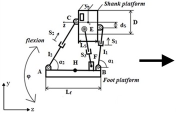
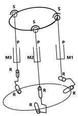
Fig. 1Comparative kinematic schemes of the Almaty ankle exoskeleton: a) V.1 with single DOF; b) V.2 with enhanced 3-DOF parallel 3RPS configuration
a)
b)
The kinematic structure of V.1 is presented in Fig. 1(a). This version is based on a traditional mechanical system that enables unidirectional motion. As shown in the diagram, the structure consists of a shank platform (upper part) and a foot platform (lower part) connected by multiple serial joints and linear electric actuators (S1, S2, S3, S4). This mechanism primarily supports a single degree of freedom (1 DOF), enabling dorsiflexion and plantar flexion of the ankle. However, this configuration does not account for inversion/eversion movements, and both the motion range and angular adaptability are limited.
The enhanced kinematic configuration of V.2 is shown in Fig. 1(b). This version integrates an advanced system comprising three electric actuators (M1, M2, M3), operating within a parallel 3RPS (revolute-prismatic-spherical) structure. This design supports three degrees of freedom (3 DOF):
– Flexion/Extension.
– Inversion/Eversion.
– Internal/External Axial Rotation.
As a result, the V.2 configuration is capable of replicating the natural range of motion of the human ankle with high precision. This design enhances lateral stability and provides adaptive movement control, allowing the device to accommodate a patient’s natural gait patterns more effectively.
This transition in kinematic design improves the anatomical alignment of the exoskeleton and enhances its adaptability to user movement. The V.2 version provides a more accurate replication of natural motion patterns, making it more suitable for rehabilitation applications.
Table 1Justification of design improvements
Parameter | V.1 | V.2 |
Degrees of freedom (DOF) | 1 (only flexion/extension) | 3 (flexion, inversion, axial rotation) |
Motion limitation | Present | Reduced |
Actuation system | Linear electric actuators | Linear electric actuators |
Flexibility | Low | High |
Biomechanical compatibility | Limited | Enhanced |
3. Comparison of CAD models
The three-dimensional (3D) CAD models of the Almaty Ankle Exoskeleton in both V.1 and V.2 versions are presented in Fig. 2. These models differ significantly in terms of geometry, structural components, and overall design approach.
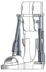
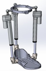
Fig. 2CAD models of the Almaty ankle exoskeleton: structural differences between a) V.1 and b) V.2 designs
a)
b)
The V.1 version features a mechanically simple yet bulky structure. The foot platform is completely enclosed, and the shank platform is a solid monolithic block shaped approximately to fit the human lower leg. Actuation elements are mounted directly onto the platforms, enabling only forward and backward flexion. This version was developed as an initial prototype to evaluate basic dorsiflexion and plantarflexion functions.
The V.2 version incorporates a refined, modular design. It utilizes three linear electric actuators arranged within a circular upper frame, symmetrically distributed around the shank. The lower foot platform is anatomically shaped, lightweight, and open in structure, which improves comfort, ease of donning/doffing, and hygiene. This design also contributes to a significant reduction in the device’s overall weight.
The structural differences between the two versions directly impact their mass, geometry, and assembly method. While V.1 is heavier and less portable, V.2 is built on a modular principle that allows for easy maintenance and replacement of components.
In terms of materials, V.1 uses dense ABS plastic, resulting in a more rigid and heavy structure. In contrast, V.2 is manufactured using lightweight PLA plastics suitable for 3D printing. This not only simplifies the production process but also reduces printing and assembly time.
Overall, the comparison of the CAD models illustrates the technical evolution of the Almaty Ankle Exoskeleton project, moving toward more user-friendly, modular, and efficient solutions.
Table 2Justification of design improvements
Criterion | V.1 version | V.2 version |
General structure | Monolithic, box-shaped | Open-frame, modular, and lightweight |
Mass (weight) | High (heavy) | Reduced (lightweight) |
Size and portability | Large, difficult to transport | Compact and easy to disassemble |
Foot platform | Fully enclosed, limited adaptation to foot shape | Open-type, anatomically contoured |
Assembly and maintenance | Monolithic, difficult to disassemble | Modular and serviceable |
Material selection | ABS plastic | PLA plastic (3D-printable) |
Aesthetics and ergonomics | Basic, technical appearance | Lightweight, modern, and ergonomic |
User adaptability | May not fully conform to foot shape | Easy to adjust to individual dimensions |
4. Evolution of prototypes
The development stages of the two physical prototypes – V.1 and V.2 – of the Almaty Ankle Exoskeleton are presented in Figure 3. These prototypes differ significantly in terms of structural design, functional capabilities, and user adaptability.
The V.1 prototype is considered an initial version produced via 3D printing. Fabricated from ABS plastic, it has a relatively simple yet bulky shape. The foot platform is fully enclosed and not anatomically contoured to the shape of the foot. Although four linear electric actuators were used for motion, the positioning angles and cable configuration limited the precision of movement. The electronic system, including the microcontroller and power supply, was externally connected, making assembly and operation more complicated.
Fig. 3Prototype evolution of the Almaty ankle exoskeleton: a) initial V.1 prototype; b) improved and modular V.2 prototype
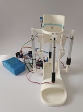
a)
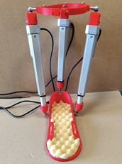
b)
The V.2 prototype demonstrates significant improvements in both functionality and ergonomic design. The foot platform is open, lightweight, and lined with soft foam on the inside to enhance user comfort. The three electric actuators are symmetrically mounted on a circular upper support, with cables routed in a compact manner. Additionally, the lower support includes rotary joints that significantly expand the range of motion.
In terms of assembly and practical application, the V.2 model offers several advantages:
1) Modular assembly allows for quick construction and easier maintenance.
2) Material selection (PLA plastic) reduces overall weight while improving strength.
3) The electrical and control systems are compactly integrated, enabling real-world testing and user trials.
Thus, the evolution from V.1 to V.2 prototypes reflects not only structural enhancements but also significant improvements in user interaction, comfort, and reliability.
Table 3Structural and functional comparison of V.1 and V.2 prototypes
Criterion | V.1 prototype | V.2 prototype |
Manufacturing method | Full 3D printing using ABS | PLA with 3D-printed components |
Foot platform construction | Fully enclosed, non-contoured interior | Open-type, foam-lined, anatomically adapted |
Ergonomics | Rigid, low comfort | Highly comfortable, with soft padding |
Motors and actuators | Static placement, imprecise angles | Symmetrical placement with optimized motion direction |
Joints and moving elements | Fixed structure | Includes rotary joints (hinges) |
Electronics and wiring | Externally exposed, not compact | Internally routed, compact and aesthetic |
Assembly / maintenance | Difficult to disassemble, non-modular | Modular, service-friendly design |
Weight | Heavy, full plastic | Lightweight, mixed materials |
Readiness for use | Suitable only for lab testing | Ready for user trials and field testing |
5. Structural analysis results of the Almaty ankle exoskeleton V.2
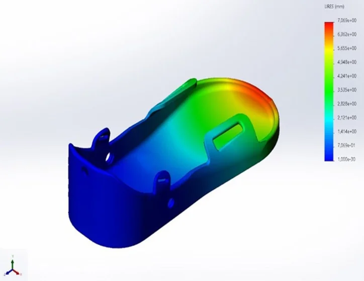
This section presents the results of a Finite Element Analysis (FEA) conducted on the V.2 version of the Almaty Ankle Exoskeleton. The simulations were performed to evaluate the mechanical strength, elasticity, and geometric deformation of the current working prototype under applied loads.
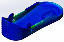
The static stress analysis is shown in Fig. 4. The distribution of von Mises stress clearly indicates the areas of the structure where the highest stress concentrations occur. The maximum stress was recorded at 51.7 MPa, corresponding to the most critical, load-bearing zones. The average stress was approximately 25 MPa, while the minimum value was 8.45 MPa. High-stress regions, marked in red, suggest the need for structural reinforcement, such as increasing material thickness or adding support elements.
The static strain analysis is presented in Fig. 5. The maximum observed strain was 1.62 % (1.62×10⁻²), and the minimum was 4.32×10⁻⁶. The strain map provides insight into the elastic behavior of the structure and identifies the regions most affected by loading.
Fig. 4Static stress analysis of ankle exoskeleton
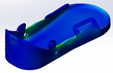
Fig. 5Static strain analysis of ankle exoskeleton
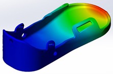
The static displacement analysis, shown in Fig. 6, reveals the extent of geometric displacement under load. The maximum displacement observed was 7.00 mm, with average displacement values ranging from 3 to 5 mm, and a minimum displacement of 1.00×10⁻³ mm. These results distinguish between the flexible and rigid areas of the structure.
Overall, the V.2 prototype demonstrates the ability to handle applied loads effectively; however, areas with high stress and displacement require additional structural reinforcement. Future work will focus on dynamic testing to better understand the device’s behavior during real-time motion and ensure its performance during actual rehabilitation use.
Fig. 6Displacement analysis of ankle exoskeleton under load
6. Conclusions
The paper presents a comparative analysis of the V.1 and V.2 versions of the Almaty Ankle Exoskeleton, with a detailed examination of their kinematic structures, CAD models, and physical prototypes. During the study, several structural and functional limitations identified in the V.1 version were addressed through technical improvements implemented in the V.2 design. In particular, the expansion of degrees of freedom, adoption of a modular design, selection of lightweight materials, and simplification of assembly processes have significantly enhanced the device’s functionality and usability.
Static analysis performed on the V.2 version using the Finite Element Analysis (FEA) method demonstrated the exoskeleton’s ability to withstand applied loads effectively, although certain high-stress regions were identified that may benefit from additional reinforcement. These findings form a foundation for further optimization of the system.
At present, the Almaty Ankle Exoskeleton V.2 is undergoing testing in real clinical settings, with ongoing efforts to integrate the device into rehabilitation processes. The results obtained so far support its potential as an effective assistive tool for enhancing the mobility of patients with neurological and orthopedic impairments.
Overall, the findings of this study establish a scientific and technical basis for the structural and functional development of ankle joint exoskeletons, paving the way for their broader implementation in clinical rehabilitation practices in the future.
References
-
B. Ostraich and R. Riemer, “Design of a multi-joint passive exoskeleton for vertical jumping using optimal control,” IEEE Transactions on Neural Systems and Rehabilitation Engineering, Vol. 30, pp. 2815–2823, Jan. 2022, https://doi.org/10.1109/tnsre.2022.3209575
-
“Ankle-H3, user manual,” https://exoskeletonreport.com/product/ankle-h3/.
-
C. Bayón, A. Q. L. Keemink, M. van Mierlo, W. Rampeltshammer, H. van der Kooij, and E. H. F. van Asseldonk, “Cooperative ankle-exoskeleton control can reduce effort to recover balance after unexpected disturbances during walking,” Journal of NeuroEngineering and Rehabilitation, Vol. 19, p. 21, Feb. 2022, https://doi.org/10.1186/s12984-022-01000-y
-
P. W. Franks, G. M. Bryan, R. M. Martin, R. Reyes, A. C. Lakmazaheri, and S. H. Collins, “Comparing optimized exoskeleton assistance of the hip, knee, and ankle in single and multi-joint configurations,” Wearable Technologies, Vol. 2, Nov. 2021, https://doi.org/10.1017/wtc.2021.14
-
J. M. Sefton et al., “The impact of a commercial lower extremity exoskeleton on metabolic load, perceived exertion, and physiological response to a challenging military relevant task: A randomized cross-over design pilot study,” PLOS ONE, Vol. 20, No. 1, p. e0314613, Jan. 2025, https://doi.org/10.1371/journal.pone.0314613
-
X. Wang, S. Guo, B. Qu, M. Song, and H. Qu, “Design of a passive gait-based ankle-foot exoskeleton with self-adaptive capability,” Chinese Journal of Mechanical Engineering, Vol. 33, p. 49, Jun. 2020, https://doi.org/10.1186/s10033-020-00465-z
-
A. Iziumov, T. S. Hussein, E. Kosenko, and A. Nazarov, “Adaptive exoskeleton device for stress reduction in the ankle joint orthosis,” Sensors, Vol. 25, No. 3, p. 832, Jan. 2025, https://doi.org/10.3390/s25030832
-
A. W. Kirby, F. Pieter L. Alison, S. Sheets, and H. Steven, “Collins improving the energy economy of human running with powered and unpowered ankle exoskeleton assistance,” Science Robotics, Vol. 5, No. 40, 2020.
-
N. Zhetenbayev, G. Balbayev, T. Iliev, and B. Bakhtiyar, “Investigation of a passive ankle joint exoskeleton designed for movements with dorsal and plantar flexion,” in International Conference on Electronics, Engineering Physics and Earth Science, Jul. 2023, https://doi.org/10.3390/engproc2023041017
About this article

The authors have not disclosed any funding.
The datasets generated during and/or analyzed during the current study are available from the corresponding author on reasonable request.
