Abstract
The dynamic characteristics of the support frame structure are critical factors influencing the safety and stability of small fishing boat. A prestressed modal analysis model of the support frame was established using the finite element method to evaluate stress, deformation, natural frequency, and modal shapes under maximum bending load conditions. To validate the accuracy of the simulated natural frequencies, the support frame was freely suspended using wide elastic ropes, and a hammering test method was employed, achieving a maximum error of less than 7.5 %. Based on a multi-objective optimization approach, optimal designs with varying thicknesses were developed to minimize stress peaks and maximize natural frequencies without increasing mass. Combining the results from strength and modal analyses, structural improvements such as adding local reinforcing ribs were proposed. Modal simulations confirmed that the optimized design can effectively mitigate low-frequency vibrations and enhance structural reliability.
Highlights
- A prestressed modal analysis model of the support frame was established using the finite element method to evaluate stress, deformation, natural frequency, and modal shapes under maximum bending load conditions.
- To validate the accuracy of the simulated natural frequencies, the support frame was freely suspended using wide elastic ropes, and a hammering test method was employed.
- Based on a multi-objective optimization approach, optimal designs with varying thicknesses were developed to minimize stress peaks and maximize natural frequencies without increasing mass.
1. Introduction
The primary function of the support frame in small fishing boat is to ensure structural stability, preventing cargo from shifting or sustaining damage due to the boat’s rolling or tilting during transportation. Additionally, it aids in distributing the cargo weight evenly, avoiding localized overloading and thereby safeguarding the integrity of the boat's structure. Consequently, the mechanical structure must maintain safety and stability under various operational conditions [1, 2]. Dynamic characteristic analysis is an essential component of the design and optimization process for the support frame. Modal analysis identifies the natural frequencies and vibration modes of the support frame, enabling the avoidance of resonance by ensuring these frequencies do not match those encountered in actual operation [3, 4]. This analysis facilitates design optimization, minimizes unnecessary vibrations, and enhances the service life and cargo efficiency of the boat. Moreover, it assists engineers in predicting and evaluating the dynamic response of the support frame under extreme sea conditions, ensuring reliability in harsh environments [5]. Load response analysis predicts and evaluates the support frame's behavior under different loads and environmental conditions, identifying potential structural weaknesses and allowing preemptive measures to be taken to prevent failures and accidents, thus ensuring the safety of both cargo and crew. In this study, based on the finite element method, the modal characteristics and strength properties of the boat's support frame under ultimate load are analyzed, accurately determining the stress distribution under dynamic loading. By forecasting the external excitation response through natural frequencies and modal shapes, multi-objective optimization methods can be applied to improve local structures.
2. Structural strength response analysis under dynamic loading
2.1. Establishment and setting of the finite element model
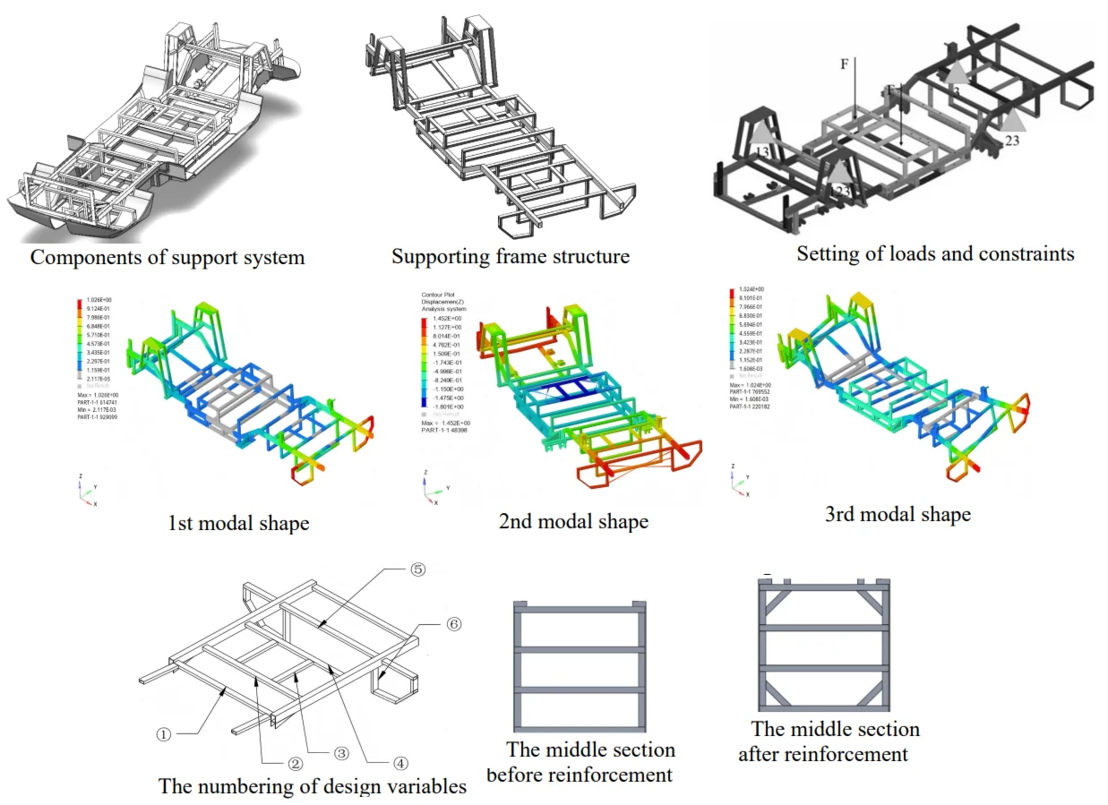
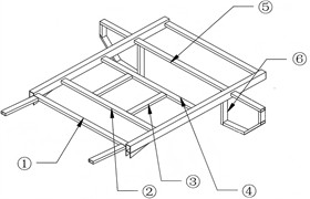
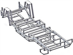
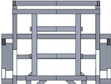
The support frame bears the majority of the load, including the gravitational forces from the boat's components and the moments generated by these components. Therefore, the mechanical structure must possess sufficient strength and appropriate rigidity while minimizing its own weight as much as possible. Under rough operating conditions, the support frame is subjected to torsional deformation due to the applied loads. As shown in Fig. 1(a), to enhance torsional resistance, the longitudinal beams are arranged in a peripheral configuration, resulting in an overall shape that follows a periodic function pattern. This design improves the frame's ability to resist torsion. To ensure that the support frame structure possesses adequate rigidity, the crossbeam and longitudinal beam are welded together. The design must comprehensively consider both the overall layout of the boat and the level of manufacturing technology. To enhance computational efficiency without compromising accuracy, complex finite element models should be simplified where appropriate. In order to accurately reflect the load-bearing capacity of the support structure, the geometric model is simplified as illustrated in Fig. 1(b). The principles guiding this simplification include:
(1) Both welding and riveting components are treated as integral parts of the structure, with stresses on weld seams and holes neglected.
(2) Installation ports that have minimal impact on the results are omitted.
(3) Irregular cross-sections are regularized to facilitate discretization while considering the actual support frame process and stress distribution.
(4) Finite element analysis issues are minimized by merging intersection points.
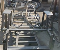
Fig. 1Structural composition of supporting frame of fishing boat
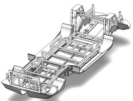
a) Components of support system
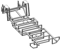
b) Supporting frame structure
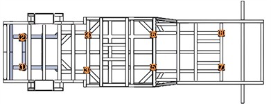
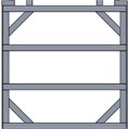
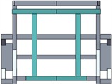
Fig. 2Setting of loads and constraints
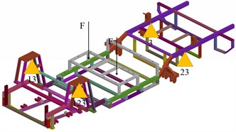
To ensure the safety of the support frame in water, the maximum vertical force is typically considered. Based on the formula for calculating the total longitudinal bending moment and applying the extremum theorem of trigonometric functions, the maximum total longitudinal bending moment experienced by the support frame under submerged conditions is determined. This moment is then converted into a concentrated vertical downward load of 17.75 kN, which is applied as a point load in the finite element model. The boundary constraints and loading conditions for the support frame under bending are illustrated in Fig. 2.
2.2. Strength and modal analysis
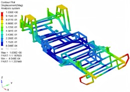
Under the maximum load condition, the stress and strain response results of the support frame are presented in Fig. 3. It is evident that the engine connection point experiences a significant concentrated load, while the front end, being distant from the beam connection point and lacking reinforcing ribs, exhibits relatively high stress concentrations. Overall, the stress levels in the support frame remain within acceptable limits, indicating a structurally safe design. The calculated maximum bending stress of 20.77 MPa is well below the yield strength of 6063 aluminum alloy, confirming that the support frame meets the strength requirements under submerged bending conditions. Under the maximum load, the front and rear sections of the support frame exhibit upward deflection, while the central section undergoes downward bending. This deformation pattern aligns with the design requirements for the support frame. Additionally, the equivalent bending stiffness of the support frame is determined to be 268.60 N/mm.
Fig. 3Strength analysis results under ultimate load
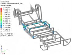
a) Stress result (unit of MPa)
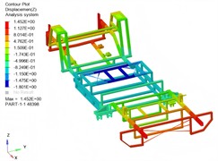
b) Displacement result (unit of mm)
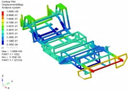
The modal shapes analysis results of the support frame are presented in Fig. 4. The study reveals that within a specific frequency range, the support frame exhibits distinct vibration modes. The first four modes are characterized primarily by overall bending, with local torsional and bending components. Significant vibration displacements occur at both ends of the support frame, particularly in the second mode, which exhibits notable symmetry.
Fig. 4Simulation results of the first four modal shapes
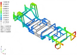
a) 1st modal shape
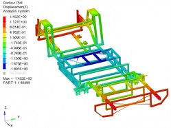
b) 2nd modal shape
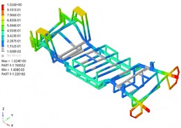
c) 3rd modal shape
d) 4th modal shape
The natural frequency is a critical parameter for evaluating modal behavior. When the excitation frequency matches or closely approaches the natural frequency, resonance can occur, potentially leading to excessive vibration amplitudes. Such high-amplitude vibrations can shorten the service life of the support frame and cause significant deformation, ultimately resulting in structural damage. Table 1 summarizes the simulation results for the natural frequencies. The first six natural frequencies range from approximately 14 to 38 Hz, all below the engine's normal operating frequency of 60 Hz, thus minimizing the risk of high-frequency resonance. However, there is some overlap with the impact frequency of water flow (approximately 5-15 Hz) and the excitation frequency caused by the transmission system, indicating a potential for low-frequency resonance. Therefore, enhancing the structural stiffness of the support frame is necessary to mitigate the likelihood of low-frequency vibrations.
To verify the reliability of modal simulation, the natural frequency is validated through experimental methods, as shown in Fig. 5. A quartz exciter and a piezoelectric accelerometer are employed for signal input and detection. The exciter, data acquisition system, and sensors are interconnected, with data transmitted to a computer for processing using modal analysis software. Given the difficulty in constraining the support frame during modal testing, a free-hanging configuration is typically adopted. In this setup, the support frame can be considered as a rigid body mode, exhibiting no bending or deformation, thereby accurately reflecting its mass and inertial properties. To ensure secure sensor installation, an adhesive method is used for reliable attachment. For accurate data collection, acceleration sensors are evenly distributed across the support frame. The frame is struck at multiple points using a force hammer, ensuring that the number of strikes exceeds the required order of modes determined by numerical analysis. Striking should avoid areas near the suspension points until the highest-order results are obtained. Prior to the main test, preliminary trials are conducted to determine optimal excitation intensity and locations. These pre-tests aim to identify excitation points that effectively excite key modes and observe corresponding mode shapes, ensuring that the coherence function of the test points meets the required standards. The verification results of the natural frequency, as shown in Table 1, indicate that all calculated deviations are below 7.5 %, confirming the high reliability of the finite element model.
Fig. 5Modal testing scheme
a) Modal testing site

b) Modal testing instrument
c) The arrangement of sensors
3. Optimization and analysis of mechanical structures
3.1. The development of an optimization strategy
To improve the structure of the support frame by applying the size optimization method, specific requirements must be set. The optimization of the support frame is carried out without changing the main structure and materials. According to the requirements of the optimization design, the objective function of the optimized structure is set as the maximum value of the first order natural frequency, with the constraint condition of not increasing the mass, as expressed in Eq. (1). That is, under the condition of being less than or equal to the initial mass, the design variables that satisfy the maximum natural frequency are solved:
where is the first order natural frequency, is initial mass.
Table 1Test and calculation results of natural frequencies
Order | 1 | 2 | 3 | 4 | 5 | 6 |
Test value of natural frequency / Hz | 13.39 | 15.97 | 24.34 | 29.05 | 33.29 | 38.44 |
Simulation value of natural frequency / Hz | 14.08 | 16.89 | 23.07 | 31.12 | 34.32 | 37.96 |
Relative error / % | 5.15 | 5.76 | 5.22 | 7.13 | 3.09 | 1.25 |
Considering the actual structural conditions, the wall thickness of the tubes is selected as the design variable. The beam at the tail of the support frame is chosen as the component for the optimization design, as shown in Fig. 6(a). To ensure that the stiffness of the new support frame after optimization is higher than that of the original support frame, the size optimization is carried out under the condition of not sacrificing the stiffness of the support frame. The stiffness requirement is converted into displacement constraints. During the analysis, the maximum bending displacement of the support frame should be less than 1.45 mm. Through optimization calculation, the design variables that meet the above performance requirements can be obtained as shown in Table 2. Typically, mathematical models are employed to calculate and extract loads under four key operating conditions: bending, torsion, steering, and braking. Among these, bending conditions generally have the most significant impact on structural strength. Therefore, this study focuses on analyzing the strength and stiffness of the support frame in water. Bending stiffness refers to the deflection value produced by the support frame under the action of the maximum load. The degree to which the support frame resists bending deformation can be reflected by the ratio of the maximum load to the corresponding maximum deformation. Under ideal conditions, it is assumed that the front and rear ends of the support frame will be subjected to the same vertical load, at which time the support frame is in a state of being low in the middle and high at both ends. Therefore, the reinforcement scheme was designed as shown in Fig. 6(b). The comparison of the reinforcement structures of the middle section and the front section is shown in Fig. 6(c) and Fig. 6(d).
Fig. 6Selection of design variables and reinforcement scheme
a) The numbering of design variables
b) The overall structure after reinforcement

c) The middle section before reinforcement
d) The middle section after reinforcement
e) The front section before reinforcement
f) The front section after reinforcement
Table 2The values of design variables
Number | Initial value / mm | Upper limit value / mm | Lower limit value / mm | The optimized value / mm |
1 | 1.5 | 2 | 1 | 1.68 |
2 | 1.5 | 2 | 1 | 1.71 |
3 | 1.5 | 1.5 | 1 | 1.33 |
4 | 1.5 | 2 | 1 | 1.56 |
5 | 1.5 | 1.8 | 1 | 1.31 |
6 | 1.5 | 1.8 | 1 | 1.27 |
3.2. Modal analysis of the optimized structure
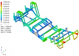
Through modal simulation of the optimized structure, it is known that the first-order frequency of the support frame is 22.35 Hz, which has exceeded the low-frequency resonance zone, effectively improving the resistance to vibration caused by water flow and the transmission system. The high-order modal characteristics of the support frame have little influence on the dynamic characteristics of the structure. In addition, the optimized support frame also meets the strength requirements, with both the maximum stress and maximum displacement showing varying degrees of reduction. It can be applied to various complex and extreme working conditions, and the maximum deformation does not exceed 2 mm. Stiffness and strength are critical factors that significantly influence the safety and comfort of a boat's overall structure. The primary load on the support frame is concentrated in the middle section between the front and rear suspension supports. Consequently, performing a comprehensive stiffness analysis of the entire support frame structure is essential.
Fig. 7Simulation results of optimized structure of modal shapes
a) 1st modal shape (22.35 Hz)
b) 2nd modal shape (23.47 Hz)
4. Conclusions
Through modal analysis of the support frame structure, the natural frequencies and vibration modes of the fishing boat were determined, providing a theoretical basis for structural optimization. On this basis, parametric modeling of the support frame structure was carried out, and dynamic characteristic analysis was conducted using the finite element method. By changing structural parameters such as the size, position and material properties of the beams, effective ways to improve the dynamic performance of the structure were found. The optimization measures mainly include: increasing the number and thickness of the support beams, and optimizing the layout of the beams. These measures help to enhance the stiffness and strength of the fishing boat’s support frame structure, reduce its mass, and thereby improve the dynamic response characteristics of the fishing boat's support frame. The support frame structure optimization method proposed in this paper is effective and can provide a reference for related ship design and manufacturing. Future research can further consider the influence of environmental factors and operating conditions on the dynamic characteristics of mechanical structures to achieve more comprehensive optimization.
References
-
A. Daşdemir, “A modal analysis of forced vibration of a piezoelectric plate with initial stress by the finite-element simulation,” Mechanics of Composite Materials, Vol. 58, No. 1, pp. 69–80, Mar. 2022, https://doi.org/10.1007/s11029-022-10012-7
-
V. Madanipour and F. Najafi, “Innovative hull cleaning robot design and control by Laguerre base model predictive control for impedance and vibration management,” IET Control Theory and Applications, Vol. 18, No. 18, pp. 2705–2724, Jul. 2024, https://doi.org/10.1049/cth2.12716
-
R. Talebitooti, M. Zarastvand, and H. Darvishgohari, “Multi-objective optimization approach on diffuse sound transmission through poroelastic composite sandwich structure,” Journal of Sandwich Structures and Materials, Vol. 23, No. 4, pp. 1221–1252, Jun. 2019, https://doi.org/10.1177/1099636219854748
-
R. Talebitooti, H. D. Gohari, and M. R. Zarastvand, “Multi objective optimization of sound transmission across laminated composite cylindrical shell lined with porous core investigating Non-dominated Sorting Genetic Algorithm,” Aerospace Science and Technology, Vol. 69, No. 1, pp. 269–280, Oct. 2017, https://doi.org/10.1016/j.ast.2017.06.008
-
X. Li, D. Zhao, H. Zhai, M. Chen, and T. Zhang, “Modal analysis of circular arches in rectangular coordinate system,” Structures, Vol. 47, No. 1, pp. 2129–2137, Jan. 2023, https://doi.org/10.1016/j.istruc.2022.12.036
About this article

The authors have not disclosed any funding.
The datasets generated during and/or analyzed during the current study are available from the corresponding author on reasonable request.
The authors declare that they have no conflict of interest.
