Abstract
Leakage accident occurred during the operation of a buried valve blowdown pipe in a natural gas station. After the macroscopic morphology, mechanical properties, chemical composition, metallography, scanning electron microscopy and energy spectrum analysis of the leaking blowdown pipe, it was found that the corrosion perforation was located in the outer wall of the pipe, and the damage of the corrosion layer caused the corrosion components in the saline soil to contact the steel pipe to produce oxygen corrosion. In addition, Cl– ions in the soil played a role in accelerating corrosion, which eventually led to the occurrence of perforation accidents.
1. Introduction
In the long-distance pipeline or petrochemical industry plant, the caliber of the blowdown pipe is usually small, and it is not the main pipeline responsible for the transmission task, so its protection is easy to receive less attention [1-5]. However, the leakage caused by its failure has the same serious consequences as the failure of the main pipeline, including production shutdown, shutdown and welding repair [6]. Once it is not handled in time, it will also cause serious accidents such as explosions. There are many reasons for the failure of such small diameter pipes, such as corrosion protection layer failure, soil environment, third-party damage, welding defects, etc. [7-8]. A comprehensive failure analysis should be conducted, encompassing the pipeline itself, the external environment, materials, and management. This analysis should be exhaustive and exclude factors that are not pertinent to the investigation. The objective is to identify the root cause of the failure [9-10]. This paper presents a case study of a leakage accident and describes the process and principles of failure analysis of underground sewage pipes.
During the comprehensive inspection process, personnel at the compressor station of a pipeline company utilized a laser detector to detect the presence of natural gas in the outbound valve area, with an accompanying odor near ground level. Subsequent testing revealed a combustible gas concentration of 5%LEL. Following this, the buried valve was excavated and examined, confirming a leak in the sewage pipeline approximately 30 cm from the bottom elbow at 1 o'clock direction. Additionally, an approximately 200 mm long continuous corrosion pit was identified on the inner bend of the pipeline.
The valve sewage pipe is SCH160 seamless steel pipe, put into use on December 01, 2009, the specification is Φ33.4 mm×6.35 mm, the material is A53 Grade B, the implementation of standard ASTM A53/A53M-07, sewage pipe transport natural gas condensate water, sewage pipe corrosion layer using solvent-free liquid epoxy coating. In order to find out the cause of leakage, the failure analysis of the failure pipe section is carried out in this paper.
2. Inspection and analysis of pipe
2.1. Macroanalysis
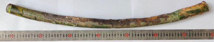
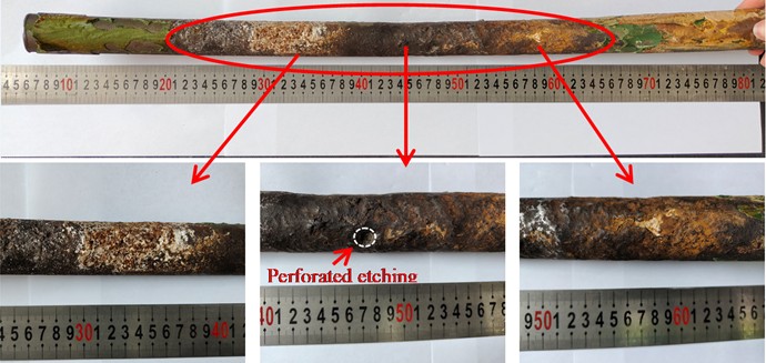
The length of the sampling tube is 680 mm, and the outer surface is covered with green epoxy anticorrosive layer. In some areas, the anti-corrosion coating has been completely removed, while in other areas, there are signs of artificial removal. There was a perforation at the 1 o’clock direction of the bend in the tube body, and a corrosion pit was visible on the outer wall of the perforation position, but no corrosion products were found in the pit, and there were signs of artificial removal. A large area of external corrosion appears within 450 mm from the perforation location, and the tube wall appears black-brown within 100 mm from the pit, and an oil-like substance is attached to the surface. Red and brown corrosion products appeared on other surfaces. White substances were found on the outer wall of the steel pipe at 280-370 mm and 500-640 mm, and yellow and white substances were also attached outside the protective layer at the end of the pipe (as shown in Fig. 1).
Fig. 1The macroscopic morphology of the sample
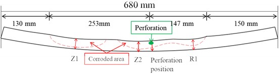
The results of scale detection are presented in Fig. 2. The outer diameter of Z1 measures 31.31 mm, that of Z2 is 31.59 mm, the perforation has an outer diameter of 27.68 mm, and R1 has an outer diameter of 31.78 mm. It is evident that the perforation exhibits the smallest outer diameter, displaying a noticeable thinning phenomenon when compared to the nominal size of 33.4 mm×6.35 mm.
Fig. 2Schematic diagram of measurement position and sample measurement results
2.2. Physical and chemical property test
(1) Vickers hardness of the tube base material. According to ASTM E92-17 [11], the hardness test was carried out with KB 30BVZ-FA hardness tester. The average Vickers hardness of the base material is 124.7HV10, and there is no obvious abnormality in the result.
(2) Chemical composition analysis of tube base material. According to ASTM A751-21 [12], the chemical composition results was obtained using ARL 4460 direct reading spectrometer (as shown in Table 1). Chemical composition meets ASTM A53/A53M-07 [13] standard requirements.
(3) Metallographic analysis of tube base material. According to ASTM E45-18a [14], ASTM E3-11(2017) [15] and ASTM E112-13 [16], the metallographic structure of the tube base material was analyzed using Olympus LEXT OLS4100 microscope, and the results are shown in Fig. 3 and Table 2. The results show no significant anomalies.
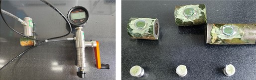
(4) Bonding strength of the coating. The Elcometer 506 pull-off adhesion tester was used to carry out the test, and the results are shown in Fig. 4. The average of the three bond strength test values was 21.03±0.05 MPa. The disengagement surface is the interface between the pull-off test joint and the adhesive used for the test, which indicates that the adhesion of the anticorrosion layer is higher than the test value.
Table 1Chemical composition analysis results of base metal (Wt×10-2)
Element | C | Mn | P | S | Cu | Ni | Cr | Mo | V |
Result | 0.12 | 0.63 | 0.013 | 0.0093 | 0.23 | 0.037 | 0.031 | 0.0046 | 0.0034 |
ASTM A53/A53M-07 | ≤ 0.30 | ≤ 1.20 | ≤ 0.05 | ≤ 0.045 | ≤ 0.40 | ≤ 0.40 | ≤ 0.40 | ≤ 0.15 | ≤ 0.08 |
Table 2Chemical composition analysis results of base metal (Wt×10-2)
Testing items / Position | Nonmetallic inclusion | Metallographic organization | Grain size | |||||||
A | B | C | D | |||||||
Thin | Thick | Thin | Thick | Thin | Thick | Thin | Thick | |||
Results | 0.5 | 0 | 0.5 | 0 | 0 | 0 | 1.0 | 0 | Ferrite and pearlite | 70 % 8.5 30 % 10.5 |
Fig. 3The metallographic structure of the tube base material
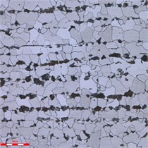
Fig. 4Adhesion test and results
2.3. Analysis of corrosion morphology and microscopic characteristics
No corrosion scale was observed in the corrosion pit of the perforation. Following the cleaning of the sampling surface, the outer surface exhibited reddish-brown and black corrosion products, as illustrated in Fig. 5 and Fig. 6 illustrates the longitudinal line cutting processing along the perforation of the longitudinal planning cross-section morphology. The inner wall of the tube, which was perforated, did not exhibit corrosion. The corrosion pits were observed to be bowl-shaped, with a diameter of 733 μm at the perforation's base. The remaining wall thickness of approximately 3 mm exhibited localized corrosion pits, with the bottom of the pits measuring approximately 1.7 mm in remaining wall thickness, as illustrated in Fig. 7.
Fig. 5Macroscopic appearance of perforation
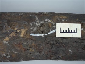
Fig. 7The morphology of the left end of the specimen in Fig. 6
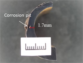
Fig. 6Morphology of longitudinal planing surfaces at perforations
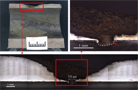
Fig. 8Results of energy spectrum analysis of corrosion products on the inner surface of perforated corrosion pit
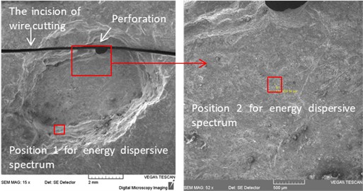
a) The micro-morphology of the inner surface of the perforated corrosion pit and the schematic diagram of the detection position of energy spectrum
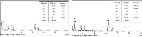
b) The results of energy spectrum analysis
The TESCAN VEGA II scanning electron microscope was employed to examine the morphology of the corroded area, while the XFORD INCA350 energy dispersive spectrometer was utilized for analyzing the substances present in this region. The results are illustrated in Fig. 8 and 9. Energy dispersive spectrum analysis of both the bottom and side walls of the corrosion pit reveals that the primary elements constituting the corrosion products at the bottom include Fe, O, C, Si, and S. In contrast, the scale-like corrosion products found on the side walls predominantly consist of Fe, O, S, Cl, and Si.
The corrosion pit in Fig. 7 was observed and the products were analyzed. As shown in Fig. 9, the corrosion pit was bowl-shaped and filled with corrosion products. The main elements of the products were Fe and O, and the main elements at the bottom of the pit were Fe, O and Cl.
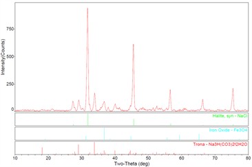
The X-ray diffraction (XRD) analysis results of the materials attached to the tube wall are shown in Fig. 10. The results show that the white substances are mainly NaCl, trona (Na3H(CO3)2H2O), and the reddish-brown corrosion product is Fe3O4.
Fig. 9The morphology of the corrosion pit corresponding to Fig. 7 and the results of energy dispersive spectrum analysis
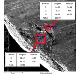
Fig. 10Results of XRD analysis of the materials attached to the outer wall of the tube
3. Investigation of the operation of cathodic protection
According to the investigation, the potentials at worked normally and there is no obvious abnormality in the potential test. The synchronous on-off point around the valve was detected, and no DC interference was found, and the historical AC interference data was in the range of 0.01 V-0.46 V.
4. Analysis of failure cause
The chemical composition, hardness and metallographic structure of the failed pipe were not abnormal. The average corrosion rate is 0.52 mm/ year. The main elements of corrosion products at the bottom of the pit are Fe, O, C, Si and S. The main elements of the scale corrosion products on the pit side wall are Fe, O, S, Cl and Si. The main elements of corrosion products on the outer wall of the pipe near the perforation are Fe, O and Cl. It shows that the corrosion area is mainly oxygen corrosion, and there are chloride ions. XRD analysis results show that there is NaCl on the outer wall of the tube, which can provide Cl– ions. According to the field investigation, the local covered soil is alkaline saline soil, locally rich in Cl– ions and HCO3– ions, which is confirmed by XRD analysis results.
Due to the presence of oxygen and water in the soil, dissolved oxygen and iron form a corroding battery. The electrode potential of iron is lower than that of oxygen, and iron is the anode in ferrite corrosion batteries. Fe in the anode region continues to lose electrons and become ions into the solution, that is, iron is constantly dissolved and corroded, and iron oxides such as Fe3O4 are generated. With the occurrence of oxygen corrosion, the corrosion gradually develops towards wall thickness. As Cl– is contained in the soil, under the condition of water, the production of metal ions will cause the excess amount of positive charge at the corrosion site, resulting in Cl– migrating to the corrosion site to maintain its electrical neutrality, and Cl– outside the corrosion pit will continue to enrich in the corrosion pit, and the solution in the pit is in a state of retention, forming a blocked corrosion battery. The blocking cell promotes the corrosion pit to develop along the wall thickness until it perforates.
The anti-corrosion layer of the pipe body far away from the corrosion area is well combined, and there is no obvious material deterioration. There is a large area of external corrosion thinning near the perforation, and the thinning is the largest at the perforation and gradually decreases to both ends, indicating that the cause of corrosion is the failure of the anticorrosive layer at the perforation. Corrosive substances in the soil penetrate or diffuse from the point of failure to the pipe wall, and contact with the steel pipe leads to corrosion. As the corrosion progresses, loose iron oxide is formed at the interface between the steel pipe and the epoxy anti-corrosion coating, resulting in interface debonding, which provides a channel for the corrosion material to spread inwards and promotes the propagation of corrosion. There are two possible reasons for the failure of the anti-corrosion coating, one is the original defect of the anti-corrosion coating in the manufacturing process, and the other is the damage to the pipe section by a third party, resulting in the penetration and diffusion of the corrosion components in the soil along the defect to the pipe wall.
5. Conclusions
For failure events, the material itself and the external environment are the two most important protagonists, and they directly interact. Therefore, both analyses should be performed. It is important to analyze the structure and composition of the abnormal phenomena and damage sites, as well as the necessary tests to rule out non-possible factors.
In this paper, the cause of failure is found out through necessary and systematic detection and result analysis. The cause of the quality defect of the pipeline material is excluded. Damage to the anti-corrosion layer occurs, resulting in corrosive components in the salty soil contacting the steel pipe to produce oxygen corrosion, and Cl– ions in the soil play a role in accelerating corrosion, ultimately leading to perforation.
To prevent the recurrence of such problems, firstly, it is necessary to ensure that the anti-corrosion layer of the buried pipeline is constructed in accordance with the relevant standards and meets the requisite specifications. Secondly, the compatibility between the preservative layer and the local soil composition characteristics should be considered and investigated in the design stage. Finally, the pipeline backfill should be comprised of less corrosive soil as far as possible.
References
-
M. A. Varnosfaderani, A. Eslami, N. Saiedi, and A. Bahrami, “Metallurgical aspects of a blowdown pipe failure in a petrochemical plant,” Engineering Failure Analysis, Vol. 98, pp. 141–149, Apr. 2019, https://doi.org/10.1016/j.engfailanal.2019.01.068
-
G. Q. Tao, Z. R. Song, J. Hu, J. F. Liu, and S. H. Zhang, “Study on drain and vent of long-distance pipeline valves,” Valve, No. 3, pp. 8–11, 2014.
-
Z. Liu, W. Liao, W. Wu, C. Du, and X. Li, “Failure analysis of leakage caused by perforation in an L415 steel gas pipeline,” Case Studies in Engineering Failure Analysis, Vol. 9, pp. 63–70, Oct. 2017, https://doi.org/10.1016/j.csefa.2017.07.003
-
H. Mansoori, R. Mirzaee, F. Esmaeilzadeh, A. Vojood, and A. S. Dowrani, “Pitting corrosion failure analysis of a wet gas pipeline,” Engineering Failure Analysis, Vol. 82, pp. 16–25, Dec. 2017, https://doi.org/10.1016/j.engfailanal.2017.08.012
-
T.-W. Ni, T.-T. Bi, and Z.-G. Yang, “Failure analysis on abnormal perforation of super large diameter buried gas pipeline nearby metro,” Engineering Failure Analysis, Vol. 103, pp. 32–43, Sep. 2019, https://doi.org/10.1016/j.engfailanal.2019.04.044
-
W. Liu, J. Z. You, K. Liu, J. Guo, and H. K. Wang, “Reasons for corrosion failure of sewage pipe section in hydroprocessing unit,” Corrosion and Protection, Vol. 45, No. 8, pp. 109–113, Aug. 2024.
-
M. Bao et al., “Failure Analysis of Shale Gas Sewage Pipeline,” Journal of Failure Analysis and Prevention, Vol. 24, No. 5, pp. 2422–2431, Aug. 2024, https://doi.org/10.1007/s11668-024-02001-w
-
Y. Chen, L. Tang, and Q. Wang, “Failure analysis of the sewage pipeline on a shale gas platform,” in Journal of Physics: Conference Series, Vol. 2499, No. 1, p. 012015, May 2023, https://doi.org/10.1088/1742-6596/2499/1/012015
-
S. Garg, S. Bansal, and Q. Murtaza, “Failure investigation of an elbow pipe used in sewage water treatment facility,” Materials and Corrosion, Vol. 75, No. 9, pp. 1185–1192, Mar. 2024, https://doi.org/10.1002/maco.202414336
-
X. Liang et al., “Perforation failure analysis of pipeline elbow at a receiving station,” Engineering Failure Analysis, Vol. 158, p. 108071, Apr. 2024, https://doi.org/10.1016/j.engfailanal.2024.108071
-
“Standard Test Methods for Vickers Hardness and Knoop Hardness of Metallic Materials,” ASTM International, ASTM E92-17, 2017.
-
“Standard Test Methods and Practices for Chemical Analysis of Steel Products,” ASTM International, ASTM A751-21, 2021.
-
“Standard Specification for Pipe, Steel, Black and Hot-Dipped, Zinc-Coated, Welded and Seamless,” ASTM International, ASTM A53/A53M-07, 2007.
-
“Standard Test Methods for Determining the Inclusion Content of Steel,” ASTM International, ASTM E45-18a, 2018.
-
“Standard Guide for Preparation of Metallographic Specimens,” ASTM International, ASTM E3-11(2017), 2017.
-
“Standard Test Methods for Determining Average Grain Size,” ASTM International, ASTM E112-13, Jan. 2013.
About this article

This research was funded by the China National Petroleum Corporation (CNPC) Basic and Prospective Scientific and Technological Special Projects for “Research on Basic Materials and Basic Components for Petroleum Engineering” (2023ZZ11), Research Project on Fatigue Life Prediction of Cut-Off Cooling Process Pipeline under Low Temperature Vibration in Tongzhou East Railway Station (Y180023KY01KF0090003), Study on On-Line Composite Repairing Technology for High Temperature Pipeline in Refining and Chemical Industry (2023DQ03-09).
The datasets generated during and/or analyzed during the current study are available from the corresponding author on reasonable request.
The authors declare that they have no conflict of interest.
