Abstract
The article examines the origin and development of vibrotechnologies for the aviation industry within the Lviv school associated with Professor Volodymyr Povidailo. The historical contribution of this school to vibration engineering is outlined, with particular attention paid to the technologies and equipment developed at Lviv Polytechnic. The relevance of vibrotechnologies to aviation is considered in terms of their application in the strengthening, grinding, polishing, and processing of aircraft components made of titanium and high-strength aluminum alloys. The paper also highlights the potential of controlled vibration in the manufacture and assembly of composite structures, as well as in the vibration testing of aircraft components. Several vibration test stands are considered, including a non-resonant eccentric-pendulum stand, a resonant stand with a hydraulic coupling operating on the basis of the Sommerfeld effect, and an inter-resonant stand with an electromagnetic drive. Their structural principles and energy-efficiency advantages are discussed. The developments presented demonstrate the continuity of the Lviv school and its contribution to modern vibration technologies for aviation.
Highlights
- The relevance of vibrotechnologies for aviation is considered through their application to strengthening, grinding, polishing, and processing of aircraft components made of titanium and high-strength aluminum alloys.
- Vibration test stands are considered, including a non-resonant eccentric-pendulum stand, a resonant stand with a hydraulic coupling operating on the Sommerfeld effect, and an inter-resonance stand with an electromagnetic drive.
- The presented developments demonstrate the continuity of the Lviv school and its contribution to modern vibration technologies for aviation.
1. Introduction
It is necessary to clarify a particular feature of the presentation of this paper. The authors of the paper are representatives of the Lviv School of Vibrotechnologies, which has a distinguished history. The founder of this School was Professor Volodymyr Povidailo, whose 100th birth anniversary is commemorated this year. Therefore, the authors consider it appropriate to pay tribute to their Teacher, who was known and respected by scientists in many countries. He always maintained scientific relations with researchers from friendly Lithuania, in particular with his contemporary, Academician Kazimieras Ragulskis. Therefore, this paper is a review article and briefly presents the achievements of Professor Volodymyr Povidailo in the field of aviation [1], which is of particular relevance to Ukraine today. Continuing the scientific traditions of their Teacher, the authors also briefly present some of their own research in this field [2-5]. Therefore, a conventional review and analysis of the relevant literature are not provided in this paper. Thus...
The article is dedicated to the 100th anniversary of the birth of Professor Volodymyr Povidailo.
Fig. 1Professor Volodymyr Povidailo (May 14, 1926 – March 5, 2012)
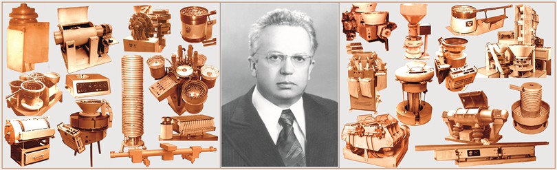
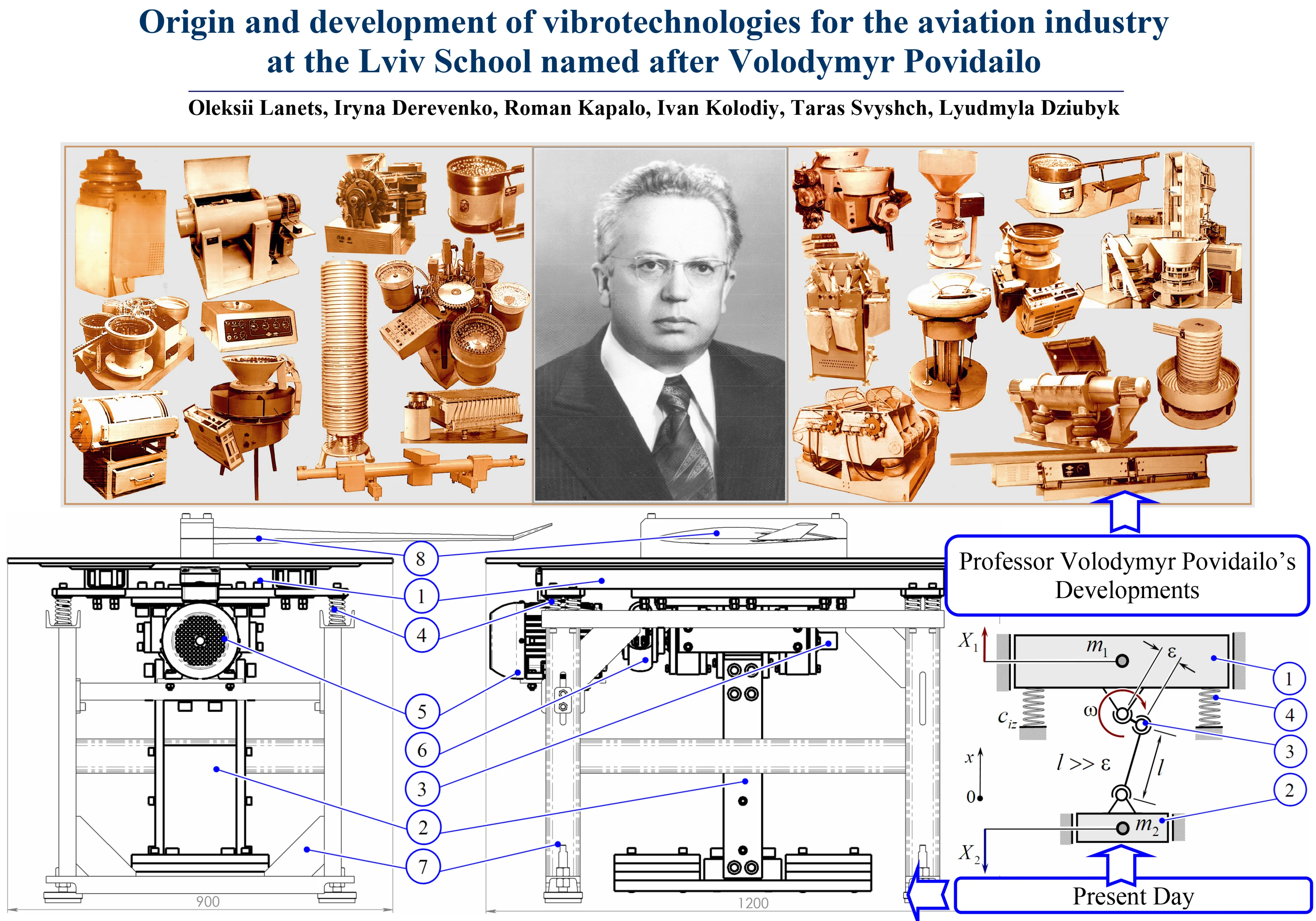
Professor Volodymyr Povidailo was an outstanding scientist and the founder of the Lviv School of Vibrotechnologies. He devoted his life to the study and development of vibration machines, revealing their versatility and unique potential. An excellent teacher and a brilliant designer, Volodymyr Povidailo succeeded in inspiring many of his students with a passion for vibration engineering. Volodymyr Povidailo’s name is associated with an entire era in the formation and flourishing of vibrotechnologies both in the Soviet Union and in Ukraine. As early as the 1960s, a new area of scientific research emerged at Lviv Polytechnic Institute within the Department of Automation and Integrated Mechanization of Machine-Building Industries, focusing on the automation of production processes using vibration engineering. This research area subsequently developed into a scientific school of vibrotechnologies, which became known as the Lviv School of Vibrotechnologies named after Professor Volodymyr Povidailo.
Today, as in the past, Lviv Polytechnic carries out a complete cycle of activities related to the research, design, manufacture, commissioning, and industrial implementation of vibratory technological equipment. Over more than 70 years of its existence, numerous vibration conveyors and hopper feeders have been developed for inspection, assembly, and counting machines, as well as for flexible manufacturing systems. Accumulators and high-precision and high-performance machines for dosing and packaging chemical substances, including highly toxic ones, have also been developed, along with vibration machines for bulk processing, surface strengthening, polishing, and grinding of parts, vibration lapping machines, and other types of equipment.
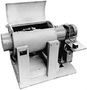
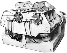
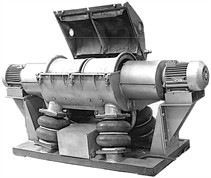
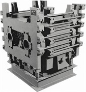
Particular attention within the scientific school is devoted to vibration technologies related to the aviation industry. Vibration strengthening, grinding, polishing, and other methods of processing aircraft components make it possible to improve the quality of their surface layers. This is particularly important when processing titanium alloys and high-strength aluminum alloys, which are widely used in aircraft manufacturing and are difficult to machine using conventional methods. Thus, a series of vibration machines with inertial and electromagnetic drives was developed for the processing of aircraft components (Fig. 2) [1].
Fig. 2Vibration machines for bulk finishing: a), b) with inertial drive for polishing or strengthening small parts; c) with inertial drive for strengthening aircraft wheel rims; d) with electromagnetic drive for strengthening aircraft wing components
a)
b)
c)
d)
At present, research is being conducted on the use of vibration during the manufacture and assembly of composite structures. Controlled vibrations contribute to material compaction, the removal of air inclusions, improved impregnation of the reinforcing filler with the polymer matrix, and increased structural uniformity. In adhesive-bonding and composite-joining technologies, vibration is applied to ensure more uniform adhesive distribution and reduce the likelihood of defect formation. An extremely important area is the vibration testing of aircraft structures. During operation, aircraft are subjected to a wide range of dynamic loads, including vibrations generated by engines and power units, aerodynamic loads, and vibrations generated by onboard equipment. Therefore, the experimental reproduction of such loads using specialized vibration test stands is an essential component of ensuring the strength, stiffness, vibration resistance, and durability of aircraft structures.
For this purpose, a series of research studies aimed at developing reliable, structurally simple, and highly efficient vibration test stands for testing aviation-industry products is being conducted at Lviv Polytechnic. The authors of this paper present the results of these developments.
2. Non-resonant eccentric-pendulum-type vibration test stand [2]
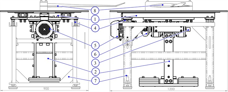
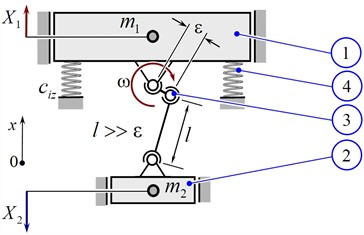
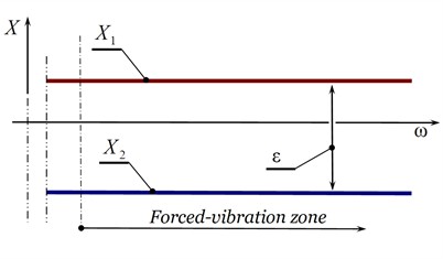
The most structurally simple vibration test stands are non-resonant designs. Their main disadvantage is the high power consumption of the drive. This type of equipment includes the non-resonant eccentric-pendulum vibration test stand, whose projection views are shown in Fig. 3(a). The vibration test stand is designed for testing aircraft components against alternating cyclic loads. Its design incorporates only one electric motor 5 and does not require mechanisms for forced guidance of the oscillatory motion. The oscillatory system of this vibration test stand is a two-mass non-resonant system (Fig. 3(b)).
Fig. 3a) Projection views, b) simplified schematic diagram, and c) amplitude-frequency response of the non-resonant eccentric-pendulum vibration test stand, where: 1 – active oscillating mass; 2 – reactive oscillating mass in the form of a pendulum; 3 – shaft with eccentricity ε; 4 – vibration isolators; 5 – electric motor; 6 – flexible disc coupling; 7 – frame; 8 – glider wing cantilever-mounted to the active oscillating mass 1
a)
b)
c)
The vibration test stand consists of a working body 1 with a mass of , mounted on frame 7 through vibration isolators 4, whose stiffness coefficient is . A shaft 3 is installed inside the housing of the working body 1, with a pendulum 2 of mass mounted on it with an eccentricity . Shaft 3 is driven by asynchronous electric motor 5 through flexible disc coupling 6. The rotational motion of shaft 3 at an angular frequency induces oscillatory motion of the two-mass system. The working body 1 oscillates in antiphase with respect to pendulum 2, while their oscillation amplitudes over the operating frequency range are and , respectively (Fig. 3(c)). The use of an eccentric-pendulum drive ensures rapid start-up and shutdown of the oscillatory system compared with unbalanced drives. The main technical characteristics of this vibration test stand are presented in Table 1.
Table 1Main parameters of the vibration test stands
Parameter | Vibration test stand shown in: | ||
Fig. 2 | Fig. 3 | Fig. 4 | |
Amplitude value of acceleration at the working body | 4 g | 7 g | 9 g |
Angular frequency of forced vibrations, , rad/s | 300 | 300 | 628 |
Mass of the working body, , kg | 313 | 168 | 207 |
Drive power consumption, | 3000 | 1500 | 300 |
More detailed information on the operating principle of this type of equipment can be found in [2]. The parameters given in Table 1 for this vibration test stand were determined through mathematical modeling of the oscillatory system represented by a set of six autonomous second-order differential equations and were confirmed by experimental studies [5].
Resonant vibration test stand with an inertial drive and hydraulic coupling based on the Sommerfeld effect [3]
Vibration test stands operating in a pre-resonant mode relative to the system’s natural frequency are becoming increasingly widespread in industry. This operating mode makes it possible to significantly reduce the power consumption of the drive. In such vibration test stands, control systems are used to stabilize the rotational speed of the unbalanced rotor in the vicinity of the resonance peak, which considerably increases the cost of the equipment and its maintenance.
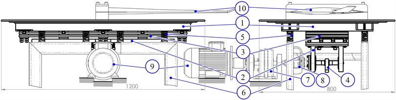
The authors of this paper have developed a resonant vibration test stand with an inertial drive actuated through a hydraulic coupling (Fig. 4(a)). The vibration test stand is designed for testing aircraft components 10 under alternating cyclic loads. The driving shaft of hydraulic coupling 7 is driven by electric motor 9. The driven shaft of hydraulic coupling 7 is connected to unbalance 4. This configuration allows the rotor of asynchronous electric motor 9 to reach its nominal operating conditions, while the rotational speed of unbalance 4 becomes “locked” in the vicinity of the resonance peak due to processes associated with the Sommerfeld effect. This makes it possible to automatically “fix” the forced-vibration frequency with near-pre-resonant tuning, thereby implementing energy-efficient operating modes in the oscillatory system of the vibration test stand. Expensive control systems are not required.
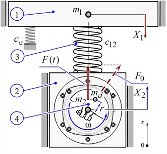
The vibration test stand consists of a working body 1 (active oscillating mass), whose inertial value is , and a reactive oscillating mass 2, whose inertial value is . The active oscillating mass 1 is connected to the reactive oscillating mass 2 through a resonant elastic unit 3, whose stiffness coefficient is . An unbalance 4 with a mass is mounted below the reactive oscillating mass 2 in a bearing assembly. The structure is mounted on a stationary base through vibration isolators 5, whose stiffness coefficient is . The vibration isolators are attached to the active oscillating mass 1.
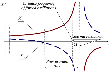
The oscillatory system is driven as follows. The rotor of asynchronous electric motor 9 drives the input shaft of hydraulic coupling 7. The rotational motion from the output shaft of the hydraulic coupling is transmitted to unbalance 4 through flexible disc coupling 8. Due to the forced rotation of the unbalance with an angular frequency , with mass whose center of mass is located at an eccentricity relative to the shaft rotation axis, a time-varying centrifugal force arises , whose amplitude vector rotates with an angular frequency (Fig. 4(b)). This produces an alternating force excitation of reactive oscillating mass 2 along the -axis. The motion of reactive oscillating mass 2 is transmitted to active oscillating mass 1 through elastic unit 3. Oscillating masses 1 and 2 move in antiphase with amplitudes and , respectively (Fig. 4(c)). The main technical parameters of the test stand are presented in Table 1.
Fig. 4a) Projection views, b) simplified schematic diagram, and c) amplitude-frequency response of the resonant vibration test stand with an unbalanced drive, where: 1 – active oscillating mass; 2 – reactive oscillating mass; 3 – resonant elastic unit; 4 – unbalance; 5 – vibration isolators; 6 – frame; 7 – hydraulic coupling; 8 – flexible disc coupling; 9 – asynchronous electric motor; 10 – glider wing cantilever-mounted to the active oscillating mass 1
a)
b)
c)
More detailed information about the operating principle of vibration equipment based on the Sommerfeld effect can be found in publication [5]. The parameters given in Table 1 for this vibration test stand were determined through mathematical modeling of the oscillatory system represented by a set of six autonomous second-order differential equations [3].
3. Inter-resonant vibration test stand with an electromagnetic drive [4]
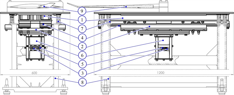
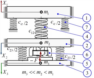
Three-mass oscillatory systems can provide significantly higher operating efficiency compared with conventional two-mass systems. This is associated with the effect of resonance superposition, which enables the release of an extremely high dynamic potential of the system. The methodology for calculating such oscillatory systems is well described in [5]. One practical implementation of this approach is the inter-resonance vibration test stand with an electromagnetic drive shown in Fig. 5(a, b). Like the previously described vibration test stands, this stand is designed for testing aircraft components 10 under alternating cyclic loads.
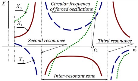
The test stand consists of a working body 1 (active oscillating mass), whose inertial value is , an intermediate oscillating mass 2, whose inertial value is , and a reactive oscillating mass 3, whose inertial value is . The active 1, intermediate 2, and reactive 3 oscillating masses are pairwise connected through resonant elastic units 4 and 5, whose stiffness coefficients are and , respectively. The structure is mounted on a stationary base through vibration isolators 7, whose stiffness coefficient is . The vibration isolators are attached to the working body 1. The force excitation of the oscillations at the angular frequency of forced vibrations is generated by electromagnetic vibration exciters 6. Their armatures are attached to the reactive mass 3, while the cores with coils are attached to the intermediate mass 2. The active 1, intermediate 2, and reactive 3 oscillating masses oscillate with amplitudes , , and , respectively (Fig. 5(c)). The main technical parameters of the test stand are presented in Table 1.
Fig. 5a) Projection views, b) simplified schematic diagram, and c) amplitude-frequency response of the inter-resonant vibration test stand with an electromagnetic drive, where: 1, 2, and 3 – active, intermediate, and reactive oscillating masses, respectively; 4, 5 – resonant elastic units; 6 – electromagnetic vibration exciter; 7 – vibration isolators; 8 – frame; 9 – glider wing cantilever-mounted to the active oscillating mass 1
a)
b)
c)
The principle of developing such high-efficiency vibration equipment is described in [4, 5]. The parameters given in Table 1 for this vibration test stand were determined through mathematical modeling and confirmed by experimental studies [5].
It should be noted that the Lviv scientific school is not limited to the research presented in this paper. Representatives of this school have published papers on the development of new high-efficiency vibration technological equipment [6-9].
4. Conclusions
The development of vibrotechnologies at the Lviv School founded by Professor Volodymyr Povidailo has laid an important foundation for modern aviation applications. Vibration strengthening and finishing technologies improve the functional quality of aircraft components, while vibration test stands enable the efficient investigation of cyclic loads and dynamic behavior. The non-resonant, resonant, and inter-resonant systems considered in this study demonstrate different approaches to achieving high dynamic efficiency and reducing energy consumption in aviation testing and research.
References
-
V. Povydailo, Vibration Processes and Equipment. (in Ukrainian), Lviv, Ukraine: Lviv Polytechnic Publishing House, 2004.
-
T. Svyshch, O. Lanets, P. Maistruk, I. Derevenko, I. Nazar, and I. Khomych, “Modeling the operation of an eccentric-pendulum resonant vibration stand for testing aviation industry products,” Vibroengineering Procedia, Vol. 59, pp. 34–40, Sep. 2025, https://doi.org/10.21595/vp.2025.25064
-
R. Kapalo, O. Lanets, P. Maistruk, A. Voitovich, I. Nazar, and I. Khomych, “Mathematical modeling of the operation of a resonant vibration stand with an inertial exciter and hydraulic coupling for testing aviation industry products,” Vibroengineering Procedia, Vol. 59, pp. 28–33, Sep. 2025, https://doi.org/10.21595/vp.2025.25059
-
I. Kolodiy, O. Lanets, P. Maistruk, I. Derevenko, I. Nazar, and I. Khomych, “Modernization of the electromagnetic vibration stand for testing aviation industry products,” Vibroengineering Procedia, Vol. 59, pp. 21–27, Sep. 2025, https://doi.org/10.21595/vp.2025.25065
-
O. Lanets, Fundamentals of analysis and design of vibratory machines. (in Ukrainian), Lviv, Ukraine: Lviv Polytechnic Publishing House, 2018, p. 612.
-
V. Gursky, P. Krot, V. Korendiy, and R. Zimroz, “Dynamic analysis of an enhanced multi-frequency inertial exciter for industrial vibrating machines,” Machines, Vol. 10, No. 2, p. 130, Feb. 2022, https://doi.org/10.3390/machines10020130
-
V. Gursky, I. Kuzio, P. Krot, and R. Zimroz, “Energy-saving inertial drive for dual-frequency excitation of vibrating machines,” Energies, Vol. 14, No. 1, p. 71, Dec. 2020, https://doi.org/10.3390/en14010071
-
V. Korendiy, O. Lanets, O. Kachur, P. Dmyterko, and R. Kachmar, “Determination of inertia-stiffness parameters and motion modelling of three-mass vibratory system with crank excitation mechanism,” Vibroengineering Procedia, Vol. 36, pp. 7–12, Mar. 2021, https://doi.org/10.21595/vp.2021.21924
-
V. Korendiy, O. Yaniv, R. Predko, I. Laushnyk, A. Dzyubyk, and S. Hrevtsov, “Trajectory-based synthesis of a three-mass vibratory system excited by a dual phase-controlled crank-slider mechanism,” Vibroengineering Procedia, Vol. 62, pp. 41–50, Jun. 2026, https://doi.org/10.21595/vp.2026.26165
About this article

The authors have not disclosed any funding.
The datasets generated during and/or analyzed during the current study are available from the corresponding author on reasonable request.
The authors declare that they have no conflict of interest.

