Abstract
Rectilinear locomotion of a semidefinite vibration-driven system on an inclined surface is studied using a one-coordinate stick-slip model and a physical prototype. The chassis and rotating assembly are treated as separate rigid bodies. General force balances retain angular-acceleration terms, and the rotor equation defines the instantaneous torque required for constant speed. A third balance resolves the two longitudinal support reactions. The reported prototype geometry and corrected mass properties yield a conservative lower bound of 0.130 N for each support-pair reaction over the investigated frequency and inclination ranges at nominal friction, conditional on the prescribed-speed planar model. The equations are transformed using the unbalance mass ratio , frequency parameter , friction coefficients and , inclination angle , and the excitation-to-weight ratio . Explicit validity conditions are established for continuous contact and bounded downhill motion, and an analytical condition for forward frictional breakaway is derived. Numerical integration uses an explicit stick-slip state-switching algorithm with transient removal and step-size verification. The frequency- and inclination-dependent predictions are compared with the experimental markers obtained for a prototype driven by a 3650-type DC vibration motor and instrumented with two WitMotion BWT901CL inertial units. The experimentally obtained points give a combined dimensionless-velocity RMSE of 0.00091 and a maximum absolute discrepancy of 0.00266. The resulting model is intended for continuous-contact, predominantly translational regimes and provides dimensionless criteria for selecting excitation and friction parameters.
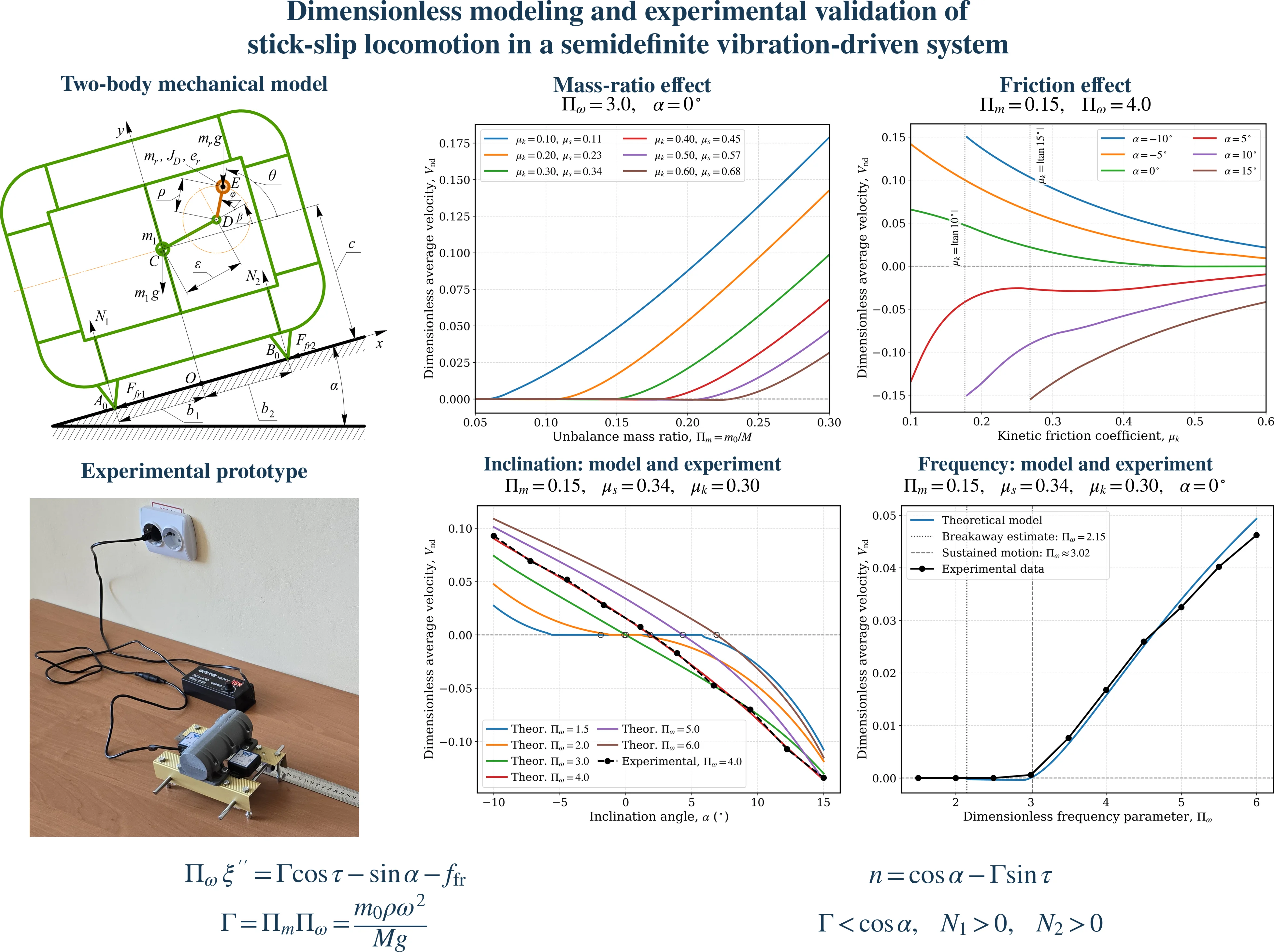
Highlights
- A dimensionless stick-slip model links rotating-unbalance excitation, dry friction and surface inclination to mean locomotion velocity.
- Continuous-contact translation requires positive reactions at both longitudinal support pairs, beyond a positive resultant normal force.
- For a horizontal surface with Πm = 0.15, μs = 0.34 and μk = 0.30, first forward breakaway occurs at Πω ≈ 2.15, whereas positive mean drift emerges near Πω ≈ 3.02.
- Constant-speed rotor operation requires a phase-dependent drive torque, which is explicitly linked to chassis acceleration.
- Predicted mean velocities are compared with prototype measurements across frequency and inclination sweeps, with five repeats per operating point.
1. Introduction
Vibration-driven locomotion systems constitute a class of semidefinite mechanical systems that move without conventional wheels, tracks, or leg mechanisms. Net translation is produced by the nonlinear interaction between an internal periodic force and dry friction at the external contact [1]-[3]. Rotating unbalances are attractive because they provide a compact, continuously driven excitation source and have been investigated in planar, pipeline, capsule, and vibro-impact robots [4]-[7]. The principal challenge is that sticking, forward sliding, backward sliding, and loss of contact are separated by state-dependent boundaries; consequently, the average velocity cannot be inferred from the harmonic force amplitude alone [8]-[11].
Recent studies have addressed discontinuous-friction modeling, sliding bifurcations, parameter optimization, and actuation design [8], [9], [11], [13], while a recent review systematizes the associated non-smooth phenomena [14]. Nevertheless, many results remain prototype-specific, and the boundaries of model validity are not always stated explicitly. In particular, a dimensionless formulation should distinguish the unbalance mass ratio from the force-to-weight excitation ratio, enforce a non-negative normal reaction, and separate the threshold of first frictional breakaway from the threshold of sustained non-zero mean locomotion.
The present study develops a reduced translational model for a two-body chassis-rotor system on an inclined surface. Its contributions are the force and moment balances needed to assess the reduction, explicit support-reaction and drive-torque conditions, and a dimensionless stick-slip formulation. Existing frequency- and inclination-dependent results are interpreted as reduced-model predictions; their experimental admissibility requires the geometric and drive checks specified below.
2. Mathematical model and validity conditions
2.1. Bodies, coordinates and constraints
The mechanical system comprises two rigid bodies: the chassis, legs and motor stator of mass , with center of mass , and the complete rotating assembly of mass , with center of mass and axial moment of inertia about shaft center . Thus . The original excitation inputs and denote an effective eccentric mass and its radius, with static moment and rotor center-of-mass offset . In general, and ; balanced rotating parts contribute to and without contributing to .
The -axis points along the surface uphill and the -axis points normally away from it. In the contact-preserving reference configuration, , , where and . The rotor phase is measured counterclockwise from the line through parallel to the positive -axis, independently of the fixed angle . Therefore . The contacts have coordinates relative to given by and .
An unconstrained planar chassis–rotor mechanism has four configuration coordinates. Sustained contact at two separated points fixes chassis normal displacement and pitch, leaving and . Prescribing leaves one independent dynamical coordinate, ; sticking temporarily fixes it. This reduction requires positive reactions at both supports, planar motion and a drive capable of realizing the prescribed phase history.
Fig. 1Semidefinite vibration-driven system and manufactured prototype
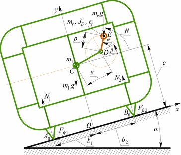
a) General two-body model and support geometry
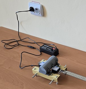
b) Experimental prototype
2.2. Force, rotor and support moment balances
Let be the signed friction resistance, so that the physical tangential contact resultant is , with . Let be the net drive couple on the rotor, where is electromagnetic motor torque and is internal mechanical resistance; the chassis receives the opposite couple. Before prescribing rotor speed, the balances in two-contact translational state are:
The terms proportional to in Eqs. (1)-(2) are the tangential components of rotor acceleration. They vanish exactly when is imposed. They are not omitted because the complete mechanism is rigid. The moment of inertia is that of the full rotating assembly, not merely the point-mass estimate . Zero angular acceleration of the chassis does not eliminate its moment balance. Resolving the shaft force and the reaction couple, and taking moments about , gives the required support moment :
The term accounts for the lever arm of the contact friction, and includes the effect of the motor reaction on the chassis. Combining Eq. (4) with yields:
The strictly maintained two-contact state requires, throughout the complete phase history:
At , that contact reaches the boundary of this model; a negative computed is inadmissible for a unilateral contact. Loss of one support permits rocking before complete separation occurs. Subsequent lift-off, flight and impact require a model with chassis normal and angular motion. For the four-tip prototype, and represent longitudinal support-pair resultants under transverse symmetry and negligible roll. Their positivity alone does not prove positive loading of all four individual tips.
Constant-speed drive and dimensionless admissibility
When and , Eqs. (1)-(2) reduce to the original harmonic force balances. Eq. (3) specifies the instantaneous net couple needed to realize that reduction:
The actual electromagnetic demand is . It must remain within the speed-dependent motoring and braking capability of the drive, with adequate response during stick-slip transitions. A constant torque larger than the maximum load does not by itself produce constant speed. If phase-resolved speed cannot be prescribed or verified, Eq. (3) must be integrated together with Eq. (1), using the measured motor characteristic and . For constant speed, substitution of Eq. (7) into Eq. (4) also gives an explicit geometry-dependent moment balance:
Define , , , , and . After division by the system weight, the original reduced force Eq. (1)-(2) become:
The inequality ensures a positive resultant for every phase, but it must be supplemented by Eq. (6). To screen the geometry in dimensionless form, introduce , , , and . Eq. (8) gives:
Thus the original force parameters do not alone specify the complete admissibility domain: , , , , and also enter support retention. Each simulated operating point must satisfy and , preferably with a margin for parameter uncertainty. For downward slopes, is retained only as a conservative screening restriction against persistent downhill sliding; it is not a contact condition or a universal requirement for every stick-slip orbit.
2.3. Friction and performance measures
With identical friction coefficients at both supports and pure chassis translation, the total sliding resistance depends on . Let . Static and kinetic friction are distinguished by and . The original piecewise law is retained:
For forward breakaway from sticking, the maximum of must exceed the gravity-plus-friction resistance. This gives the analytical condition:
The corresponding critical frequency estimate is:
The average dimensionless velocity is a kinematic performance criterion. After discarding the transient interval, it is evaluated over excitation periods as:
3. Experimental and numerical methodology
The experimental prototype was equipped with a 3650-type DC vibration motor with adjustable eccentric weights and powered by a ZY-009 regulated DC power supply. Two WitMotion BWT901CL nine-axis inertial measurement units were rigidly mounted at symmetrical locations on the chassis. The supporting track was made of smooth melamine-laminated particleboard, while the prototype contacted the track through four polished steel rod tips. The inclination angle was set using a digital inclinometer with an estimated uncertainty of ±0.2°. The static and kinetic friction coefficients were identified for the actual steel-laminated-particleboard contact pair using a combined experimental procedure. The static friction coefficient was determined from the critical inclination angle corresponding to the onset of sliding, whereas the kinetic friction coefficient was evaluated through constant-velocity pull tests performed using a digital force gauge. The measurements were averaged over ten repetitions, yielding nominal values of 0.34 and 0.30, respectively.
The primary estimate of the average locomotion velocity was obtained by dividing the measured travel distance of 0.50 m by the corresponding travel time recorded using a digital stopwatch. The actual rotor frequency was determined from the dominant spectral peak of the mean longitudinal acceleration signal rather than inferred solely from the supply voltage. The rotor-frequency variation during each experimental run did not exceed 2 %. The IMU signals were sampled at 200 Hz. Initial synchronization was performed by aligning the software timestamps of the sensors, followed by cross-correlation of the longitudinal acceleration signals during post-processing. Before further analysis, the signals were corrected for sensor bias and gravity projection and then processed using a fourth-order zero-phase Butterworth low-pass filter with a cut-off frequency of 25 Hz. The mean value of the two longitudinal acceleration signals was treated as the translational acceleration of the chassis. Their difference and the measured angular velocities provide diagnostics for chassis rotation, but no quantitative pitch bound or individual contact-force history is reported here. Each operating point was tested five times. The initial transient interval corresponding to the first ten excitation cycles was excluded when evaluating the steady-state average locomotion velocity.
The stated frequency variation concerns the reported run-level frequency estimate. A spectral peak does not bound intracycle angular acceleration or demonstrate the instantaneous torque balance in Eq. (3). Verification should report the phase history and the dimensionless indicators and . The different experimental and numerical transient windows must also be checked against convergence of the measured cycle averages.
The original numerical procedure tracked sticking, forward sliding and backward sliding, with return-to-stick events located within a phase step . It discarded 50 cycles and evaluated 100 subsequent cycles using Eq. (15). Its step-halving change was at most 1.2×10⁻⁴. The recomputed frequency panel uses analytic integration over each slip interval, with event roots located at zero velocity or static breakaway, and the same 50-cycle transient and 100-cycle observation windows. It assumes 0.34, 0.30, 0.15 and . The dimensionless velocity tolerance was 10-9. After a slip-stop event was located, residual velocities satisfying were set to zero. A sticking interval was accepted only when the static-friction condition was also satisfied, where the additive tolerance accounts for floating-point roundoff. Table 1 distinguishes the experimental prototype mass from the idealized parameter sweeps; Table 2 supplies the additional geometric and inertial inputs.
The experimental prototype and SolidWorks data give 0.070 m, 0.085 m and 0, so that . The convention may be adopted because its value has no effect when the offset vanishes. The nonzero 0.015 m is the shortest distance from the rotating mass center to the shaft; it is distinct from . For the calculations below, the reported 0.15 kg, central inertia and are interpreted as properties of the same rotating assembly, giving , and 0.83 kg. The total mass remains 0.98 kg.
Table 1Physical parameters, dimensionless ranges, and numerical settings
Parameter description | Symbol | Value / Range | Parameter description | Symbol | Value / Range |
Total mass | 0.98 kg | Mass ratio | 0.05…0.30 (0.15 nominal) | ||
Unbalanced mass | 0.15 kg | Frequency parameter | 1.5…6.0 (4.0 nominal) | ||
Eccentricity radius | 0.015 m | Inclination angle | –10°…+15° | ||
Friction coefficients | / | 0.10…0.68 (0.34 / 0.30 nominal) | Integration | ; ; | π/1000; 50; 100 |
Table 2Experimental prototype geometry and corrected rotating mass properties
Quantity | Meaning | Value |
, | Longitudinal support distances | 70 mm each |
Normal height of chassis center of mass C | 85 mm | |
, | Shaft offset from C; angle convention | mm; |
, | Reported rotating mass and mass-center eccentricity | 150 g; 15 mm |
Reported central inertia about an axis parallel to D | 14440 g∙mm² | |
Inertia transferred to shaft axis D | 48140.5 g∙mm² | |
Static unbalance used in prototype calculations | 0.0022467 kg∙m |
The central inertia is 1.444×10⁻⁵ kg∙m2. The parallel-axis theorem gives the shaft-axis inertia required in Eq. (3):
Thus the corrected prototype mass ratio is 0.15/0.98 = 0.153. The parameter sweeps with 0.15 remain idealized reference curves. Predictions compared quantitatively with the prototype must use its identified static moment and exact normalization. The following support calculation uses the corrected prototype values.
Set 0.002292551 m. Substituting Eqs. (1)-(2) into Eq. (7) at constant speed, and using , gives:
The friction law satisfies during sticking and sliding, provided . Since , maximizing over phase produces the sufficient support bound:
For 0.34, 0.03132144 m is less than 0.070 m. Hence positive implies positive reactions at both longitudinal support pairs for this geometry. Over –10° 15° and 1.5 6, the minimum possible resultant satisfies:
These conservative bounds apply to every rotor phase, including translational transients, within the prescribed-speed planar model. They are not measured reaction minima. At the nominal 0, 4, each reaction is at least 1.0323 N. Even the larger friction value 0.68 gives 0.06057238 m and a positive lower bound of 0.03166 N for each pair over the same frequency-inclination rectangle. The result therefore addresses local longitudinal unloading as well as complete separation, while remaining conditional on the reported geometry, unbalance, friction law and constant rotor speed.
Eq. (17) also gives a conservative envelope for the ideal net rotor torque. With and nominal friction:
This envelope bounds the required net couple within the stated model; it does not demonstrate that the actual motor can supply it. Electromagnetic demand must include losses, and operation must be assessed against the torque-speed characteristic, current limits and control response. Startup also introduces the term. Phase-resolved speed records, or a coupled rotor calculation using the measured drive characteristic, are needed to assess the constant-speed approximation. The two positive pair resultants do not independently establish the loading of all four physical tips; coplanarity and transverse symmetry remain assumptions of the planar reduction.
4. Results and discussion
Fig. 2(a) shows the influence of the unbalance mass ratio. The frequency parameter is set to 3 so that the complete range 0.30 remains inside the continuous-contact domain at 0°. Increasing increases and therefore raises the average velocity after the frictional breakaway threshold is exceeded. The dependence is nonlinear and monotonic within each displayed branch; no polynomial law is assumed. Individual support reactions must also satisfy Eq. (11). With the reported symmetric geometry, Eq. (18) provides a sufficient test using for each mass ratio. The ranges in Table 1 describe separate parameter sweeps; their unrestricted Cartesian product need not preserve contact.
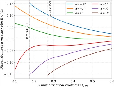
Fig. 2(b) confirms the strong sensitivity to friction. The dotted limits 0.176 and 0.268 are conservative screening boundaries for persistent gravity-directed sliding, not additional contact conditions. For = –10°, the interval 0.176 is excluded from the reported parameter sweep according to the adopted conservative screening condition . This condition restricts the investigated parameter domain to reduce the possibility of persistent gravity-directed sliding; it does not establish the non-existence of bounded stick-slip motion throughout the excluded interval. Outside the excluded intervals, the remaining curves approach zero as friction increases, while positive inclinations can produce negative average motion when the gravity component dominates. Local changes of slope are consistent with changes in the sequence and duration of sticking and sliding states, but a detailed bifurcation classification is outside the present reduced model.
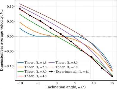
The inclination sweep in Fig. 2(c) identifies the stall and reversal region directly from the intersections with . Increasing generally expands the uphill capability, but the effect is constrained by . Black markers are means of five experimental repeats at 4.0; error bars are one sample standard deviation. Their increase near reversal reflects the sensitivity of switching times to small parameter perturbations.
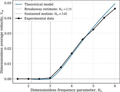
In Fig. 2(d), Eq. (14) predicts the first possible forward breakaway at 2.15 for 0.15, 0.34, 0.30 and 0°. The numerically observed reversal toward positive mean drift is higher, 3.02, because the first slip events do not necessarily produce a positive displacement balance over the complete excitation period. This distinction prevents the frictional breakaway threshold from being misidentified as the locomotion threshold.
Table 3Validation metrics obtained from the plotted experimental markers
Validation sweep | Points | RMSE | MAE | Maximum absolute error |
Inclination angle | 10 | 0.00118 | 0.00091 | 0.00266 |
Frequency parameter | 10 | 0.00051 | 0.00043 | 0.00105 |
Combined | 20 | 0.00091 | 0.00067 | 0.00266 |
Quantitative errors were evaluated from the experimentally obtained markers (see Table 3). The inclination sweep gives RMSE = 0.00118 and a maximum absolute discrepancy of 0.00266; the frequency sweep gives RMSE = 0.00051 and a maximum discrepancy of 0.00105. The combined RMSE is 0.00091. These absolute metrics are preferable to percentage error near the onset and stall points, where the reference velocity approaches zero.
It is necessary to mention that the considered numerical results are obtained within the prescribed-speed reduction, conditional on support admissibility. The velocity comparison is restricted to the measured kinematic observable. Exact RMSE, MAE and maximum-error values require a reconciled set of paired predictions and original repeated measurements, with the same mass ratio and normalization. The agreement of mean velocities cannot establish positive individual support reactions or negligible intracycle rotor acceleration. Therefore, further numerical and experimental investigations should be conducted.
Fig. 2Dimensionless numerical dependencies and experimental markers
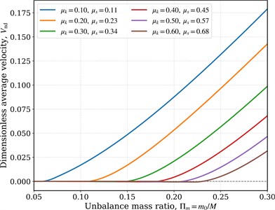
a) Dimensionless average velocity versus mass ratio (3.0, )
b) Dimensionless average velocity versus friction coefficient ( 0.15, 4.0)
c) Average velocity versus surface inclination angle ( 0.15, 0.34, 0.30)
d) Velocity versus frequency parameter ( 0.15, 0.34, 0.30, 0°)
5. Conclusions
A consistent chassis-rotor model has been formulated with separate rigid bodies, general angular-acceleration terms, rotor dynamics and a support moment balance. The original harmonic force equations follow when the rotor phase is prescribed and both supports remain active. The inequality controls only the resultant normal reaction; the additional inequalities and are required to prevent local lift-off and rocking within the planar reduction. Constant-speed operation additionally requires the phase-dependent net torque in Eq. (7), rather than an unspecified constant motor torque.
Using the reported symmetric support geometry and corrected static unbalance, the analytical check yields , 0.12989 N over the investigated frequency-inclination rectangle at nominal friction. The corrected shaft-axis inertia is 4.81405×10⁻⁵ kg∙m2 under the stated interpretation of the CAD assembly. These results establish contact admissibility within the prescribed-speed planar model. Drive characteristics and phase-resolved measurements remain necessary to verify that the experiment realizes this regime. For the idealized mass ratio 0.15, first forward breakaway near 2.146 remains distinct from reversal toward positive mean drift near 3. Flight, impact, appreciable chassis rotation and variable rotor speed require the corresponding extended equations.
References
-
X. Zhan, J. Xu, and H. Fang, “A vibration-driven planar locomotion robot-Shell,” Robotica, Vol. 36, No. 9, pp. 1402–1420, 2018, https://doi.org/10.1017/s0263574718000383
-
R. Zhu, Y. Zhang, and H. Wang, “Miniature mobile robot using only one tilted vibration motor,” Micromachines, Vol. 13, No. 8, p. 1184, Jul. 2022, https://doi.org/10.3390/mi13081184
-
S. M. Mousavi and V. Fakhari, “Design and development of closed-loop controllers for trajectory tracking of a planar vibration-driven robot,” Journal of Vibration and Control, Vol. 31, No. 17-18, pp. 3691–3704, Sep. 2024, https://doi.org/10.1177/10775463241276026
-
V. Korendiy, V. Gursky, O. Kachur, P. Dmyterko, O. Kotsiumbas, and O. Havrylchenko, “Mathematical model and motion analysis of a wheeled vibro-impact locomotion system,” Vibroengineering Procedia, Vol. 41, pp. 77–83, Apr. 2022, https://doi.org/10.21595/vp.2022.22422
-
V. Korendiy et al., “Motion simulation and impact gap verification of a wheeled vibration-driven robot for pipelines inspection,” Vibroengineering Procedia, Vol. 41, pp. 1–6, Apr. 2022, https://doi.org/10.21595/vp.2022.22521
-
V. Gursky, I. Kuzio, and V. Korendiy, “Optimal synthesis and implementation of resonant vibratory systems,” Universal Journal of Mechanical Engineering, Vol. 6, No. 2, pp. 38–46, Aug. 2018, https://doi.org/10.13189/ujme.2018.060202
-
V. Korendiy, O. Kotsiumbas, V. Borovets, V. Gurey, and R. Predko, “Mathematical modeling and computer simulation of the wheeled vibration-driven in-pipe robot motion,” Vibroengineering Procedia, Vol. 44, pp. 1–7, Aug. 2022, https://doi.org/10.21595/vp.2022.22832
-
Z. Du, H. Fang, X. Zhan, and J. Xu, “Experiments on vibration-driven stick-slip locomotion: a sliding bifurcation perspective,” Mechanical Systems and Signal Processing, Vol. 105, pp. 261–275, Dec. 2017, https://doi.org/10.1016/j.ymssp.2017.12.001
-
B. Diao, X. Zhang, H. Fang, and J. Xu, “Bi-objective optimization for improving the locomotion performance of the vibration-driven robot,” Archive of Applied Mechanics, Vol. 91, No. 5, pp. 2073–2088, Jan. 2021, https://doi.org/10.1007/s00419-020-01870-5
-
P. Vartholomeos and E. Papadopoulos, “Analysis, design and control of a planar micro-robot driven by two centripetal-force actuators,” in Proceedings 2006 IEEE International Conference on Robotics and Automation, 2006. ICRA 2006, pp. 649–654, 2006, https://doi.org/10.1109/robot.2006.1641784
-
H. Fang and J. Xu, “Stick-slip effect in a vibration-driven system with dry friction: sliding bifurcations and optimization,” Journal of Applied Mechanics, Vol. 81, No. 5, p. 051001, May 2014, https://doi.org/10.1115/1.4025747
-
V.-D. Nguyen and N.-T. La, “An improvement of vibration-driven locomotion module for capsule robots,” Mechanics Based Design of Structures and Machines, Vol. 50, No. 5, pp. 1658–1672, May 2022, https://doi.org/10.1080/15397734.2020.1760880
-
J. Xue, S. Zhang, and J. Xu, “Modelling and actuation optimization of a self-propelled robot subject to discontinuous friction,” Acta Mechanica Sinica, Vol. 41, No. 10, Aug. 2025, https://doi.org/10.1007/s10409-024-24567-x
-
Y. Liu, “Non-smooth dynamics of vibration-driven robots: A review,” International Journal of Non-Linear Mechanics, Vol. 188, p. 105377, Apr. 2026, https://doi.org/10.1016/j.ijnonlinmec.2026.105377
About this article

The authors have not disclosed any funding.
The datasets generated during and/or analyzed during the current study are available from the corresponding author on reasonable request.
Prof. Vitaliy Korendiy is a chair of the 78th International Conference on Vibroengineering and was not involved in the editorial review and/or the decision to publish this article.

