Abstract
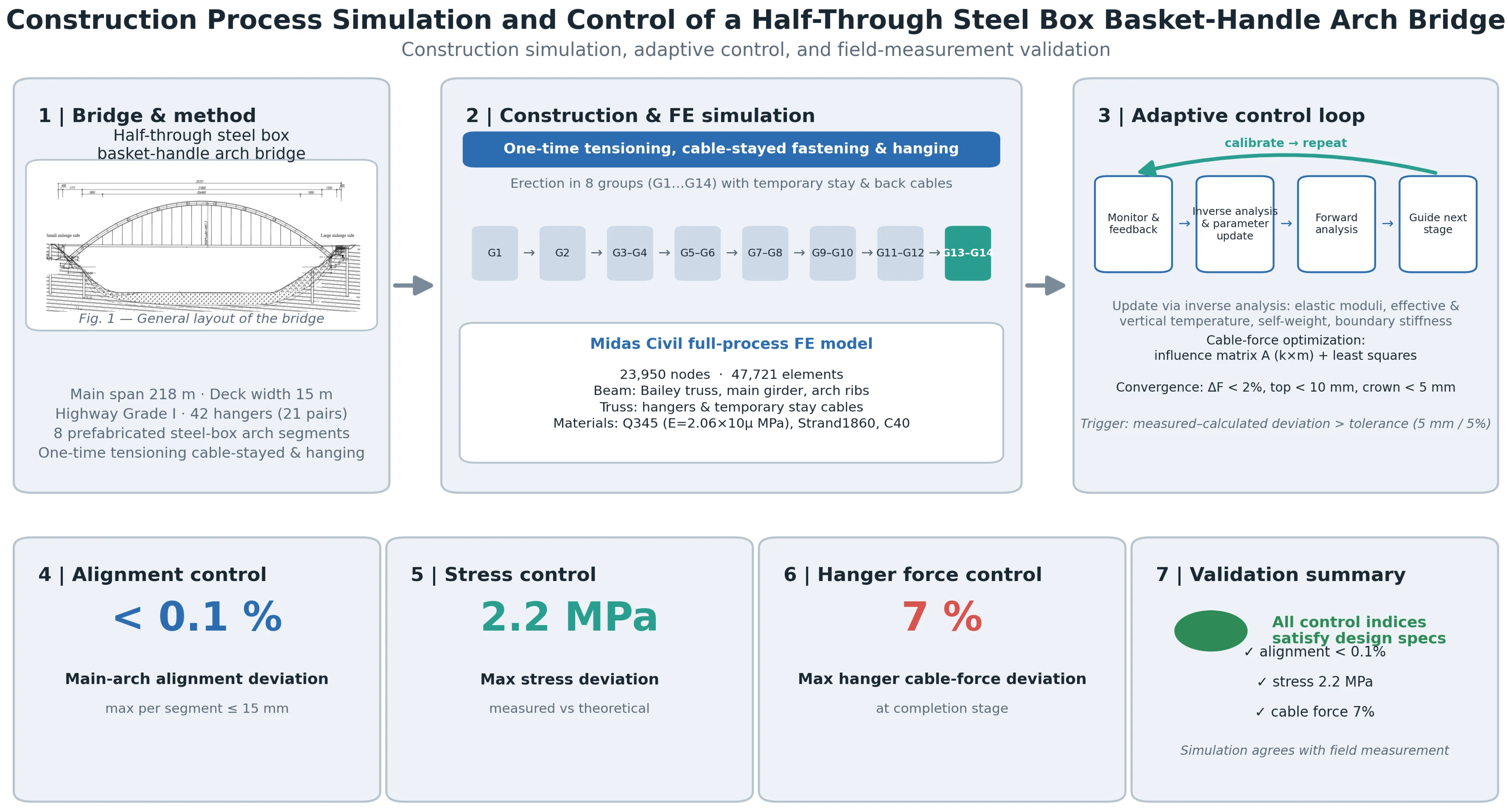
To investigate the key technical challenges in the construction control of steel box basket-handle arch bridges, this paper takes a half-through steel box basket-handle arch bridge as the engineering background. The bridge is constructed using the one-time tensioning cable-stayed fastening and hanging method. A full-bridge finite element model is established using Midas Civil to conduct simulation analysis of the entire construction process, and the numerical results are compared with field measurements. The results indicate that the overall deviation of the main arch alignment is less than 0.1 %; the maximum deviation between measured and theoretical stresses in the main arch is 2.2 MPa; and the maximum deviation between measured and theoretical hanger cable forces at the completion stage is 7 %. All these control indices satisfy the requirements of the design specifications. The proposed method can provide theoretical basis and technical reference for the construction control of similar bridges.
Highlights
- The one-time tensioning cable-stayed fastening and hanging method is adopted, combined with an influence matrix and least-squares optimization of cable forces. Adaptive control is introduced to achieve accurate simulation and control throughout the construction process.
- The maximum deviation of the main arch alignment is less than 0.1%, the maximum deviation between measured and theoretical stresses is only 2.2 MPa, and the maximum deviation of hanger cable forces in the completed bridge is 7%, all meeting code requirements.
- Taking a 218 m half-through steel box basket-handle arch bridge as a case study, the effectiveness of the one-time tensioning method is verified, providing technical reference and theoretical basis for construction control of similar bridges.
1. Introduction
Steel box basket-handle arch bridges have been widely adopted in long-span bridge construction due to their superior structural performance and aesthetic appeal[1]. However, their construction process is complex, particularly when employing cable crane erection combined with cable-stayed fastening and cantilever assembly techniques. In such cases, the determination of cable forces in the temporary stay cables and the positioning elevations of the arch segments constitute the core challenges in construction control [2-4]. Traditional methods often require multiple tensioning and adjustment cycles, which not only result in low efficiency but may also lead to cable force loss or even slippage due to strand relaxation [5-7].
In recent years, the cable-stayed buckle (fastening and hanging) method has become a predominant technique for erecting long-span arch bridges worldwide owing to its limited site occupation and millimeter-level installation precision [8]. Considerable international research has therefore been devoted to the associated construction-control problems. On the optimization of temporary cable forces, Zhang et al. [9] developed a constrained optimization of buckle and anchor cable forces under one-time tensioning for a 310 m asymmetric steel truss arch bridge, showing that an influence-matrix-based formulation achieves the target arch shape without repeated adjustments. Hou et al. [10] introduced a dynamic, stage-by-stage cable-force optimization based on particle-swarm algorithms to maintain geometric and stress control throughout the assembly. Concerning the cable-stayed fastening hardware. Huang et al. [11] presented an analytical method for the tower load in large-span arch bridge cable-lifting construction. However, most existing studies have focused on concrete-filled steel-tube arch or truss arch structures, and research on construction control for mid-supported steel-box basket-arch bridges built using the one-time tensioning cable-stayed and suspended method remains limited. To address this, this paper takes a specific medium-span steel-box basket-arch bridge as its engineering case study. The bridge was constructed using the single-stage tensioning, cable-anchoring, and suspension method. Through a comparative analysis of measured and theoretically calculated values, this study verifies the validity of this construction method and provides a technical reference for the construction of similar bridges.
2. Project overview
This study considers a half-through steel box basket-handle arch bridge with a 218 m main span, 15 m deck width, and Highway Grade I loading. Its steel box arch rib is prefabricated in eight segments, the longest about 18 m, and erected by cable crane cantilever assembly combined with the cable-stayed fastening and hanging method. The bridge has 21 pairs (42) of hangers tensioned in three stages. Fig. 1 shows the general layout.
Fig. 1General layout of the bridge (unit: cm)
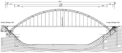
a) Elevation view
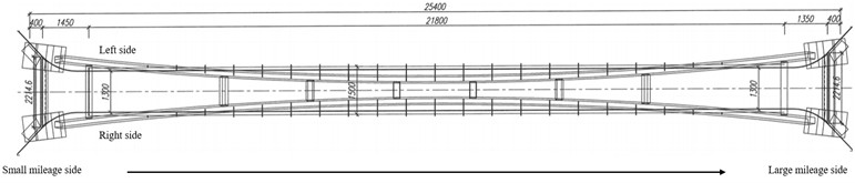
b) Plan view
3. Construction control theory and method
3.1. Basic principle of the one-time tensioning method
The one-time tensioning method refers to a construction technique in which, during the installation of each arch box segment, the corresponding temporary stay cable is actively tensioned once to a target cable force, with no subsequent adjustments. Its core objective lies in determining the appropriate initial tensioning force, so that the arch rib alignment and internal forces after bridge completion closely approximate the design bare-arch state.
Consider a half-span structure with a total of temporary stay cables, corresponding to arch box segments (excluding the closure segment). Let the initial tensioning force of the -th temporary stay cable be denoted as . The determination method is as follows: the installed segments are assumed to be rigidly connected, and the cable force of the first segment is solved based on static equilibrium conditions. For the -th segment, a tensioning force is applied to the -th cable on the existing structural system (which includes the first -1 cables already in place), so that the leading end of this segment reaches the design bare-arch alignment. The resulting cable force at this stage is taken as .
3.2. Cable force optimization method
Given that multiple control objectives (such as arch crown elevation, pylon displacement, cable force deviation, etc.) are involved in actual construction, the initial tensioning forces need to be optimized and adjusted. Assuming a total of control parameters and m cables, an influence matrix is constructed, in which each element denotes the increment of the -th control parameter due to a unit tensioning force applied to the -th cable. Let the target control parameter vector be denoted as , and the control parameter vector obtained from forward analysis under the current cable force vector be . The deviation vector is then expressed as . The cable force adjustment vector is to be determined such that the following condition is satisfied:
Since the number of equations generally exceeds the number of unknowns, the least squares method is adopted for the solution, i.e., to minimize the sum of squared residuals as follows:
This iterative process continues until the specified convergence criteria are satisfied: the maximum relative change in cable force between two consecutive iterations is strictly less than 2 %, the tower-top displacement is less than 10 mm, and the crown elevation error is less than 5 mm. A 2 % upper limit is adopted as a single, unified convergence tolerance to ensure closure accuracy and alignment control precision.
3.3. Determination of erection elevations for arch rib segments
The erection elevation of arch rib segment is obtained by subtracting the cumulative deformation at that node during subsequent construction stages from the design bare-arch elevation , i.e., , where is computed through forward analysis with temperature corrections taken into account.
3.4. Construction control method
The construction control of this bridge adopts an adaptive control method, the basic principle of which is to identify key parameters from feedback data measured during construction and to continuously update the model accordingly. This allows the analytical model to automatically adapt to the actual structural behavior after being calibrated against the real structure, thereby effectively reducing model errors. Once the simulation model can accurately reflect the actual construction process, it is then employed to guide the subsequent construction stages.
In this project, the MIDAS Civil model is updated via inverse analysis of measured feedback and structural parameters: (1) elastic moduli of steel and cast-in-place concrete; (2) effective temperature and vertical temperature gradient; (3) self-weight and geometric stiffness of erected arch segments; and (4) boundary/support stiffness at arch ends and measured tensions of temporary and back cables, all used as correction terms. Model updating is triggered when the measured–calculated deviation at a control section (typically cantilever-end displacement or monitored flange stress) exceeds a predefined tolerance (e.g., 5 mm or 5 %). Least-squares parameter identification then minimizes the residuals; the identified parameters are written back, and a new forward analysis is performed before guiding the next construction stage.
4. Finite element modeling
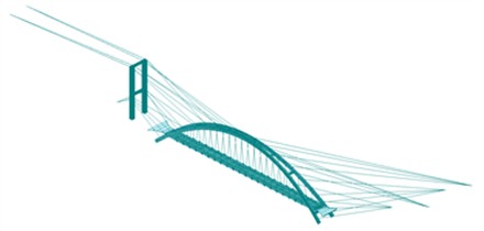
Taking a half-through steel box basket-handle arch bridge as the engineering background, this paper establishes a construction finite element model using Midas Civil, as shown in Fig. 2. The model consists of 23,950 nodes and 47,721 elements. The Bailey trusses, main girder, and main arch ribs are simulated using beam elements, while the hangers and temporary stay cables are modeled using truss elements. The coordinate system is defined as follows: denotes the longitudinal direction, the transverse direction, and the vertical direction. At both ends of the main girder, translations in the and directions and rotation about the axis are constrained. Full fixed supports are applied to the Bailey trusses, the bases of the main arch ribs, and the outer ends of the temporary stay cables. The hangers are connected to the main girder via lifting lugs and cross beams. The Bailey trusses are made of 16Mn steel with an elastic modulus of 2.10×10⁵MPa; the main girder and main arch ribs are made of Q345 steel with 2.06×10⁵MPa; the hangers and temporary stay cables are made of Strand1860 steel strands with 1.95×10⁵MPa; and the cast-in-place slabs are made of C40 concrete with 3.25×10⁴MPa.
The arch ribs are erected by the cable-stayed fastening and hanging method. Main procedures: excavate foundation pits and construct prestressed anchor blocks; place reinforcement and segmentally cast arch seats. After tower cranes are installed, assemble the cable-stayed tower and cable crane tower and arrange wind guy cables. Hoist arch rib segments in eight groups (G1, G2, G3-G4, G5-G6, G7-G8, G9-G10, G11-G12, G13-G14), simultaneously tensioning temporary stay cables and back cables and adjusting elevations. Then cast in-segment concrete and tension prestressing tendons. After hoisting and welding closure segment G14, release temporary stay and back cables in a “last-installed, first-dismantled” order to complete the superstructure, followed by hanger tensioning and main girder completion.
Fig. 2Construction finite element model
5. Construction control results and analysis
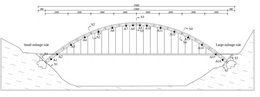
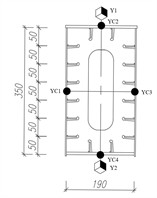
To effectively control and reasonably adjust the key parameters during the entire construction process, including the arch rib alignment, structural internal forces, and hanger cable forces, the monitoring points are arranged based on the construction characteristics of this bridge and the principle of the most unfavorable loading conditions, as described below.
Fig. 3Layout of monitoring points (unit: cm)
a) Longitudinal layout of monitoring points
b) Monitoring point layout on main arch cross-sections
For main arch alignment monitoring, surface-bonded strain gauges (Y1-Y2) are installed at the upper and lower flanges of critical sections (two arch springings, L/4, L/2, and 3L/4), totaling 20 points for the bridge. For geometry monitoring, welding prisms (YC1-YC4) are placed at the midpoints of the four sides of each arch rib cross-section per erected segment, with 16 points (A1-A16) per arch rib and 32 for the bridge; YC4 displacement data are mainly used. Additionally, one point per hanger measures cable force, totaling 42 points. The layout is shown in Fig. 3.
5.1. Main arch alignment control results
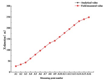
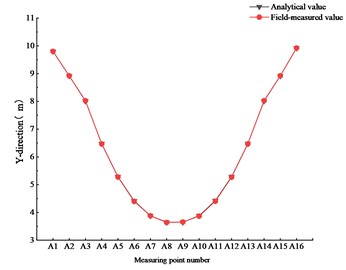
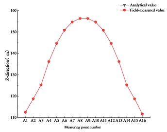
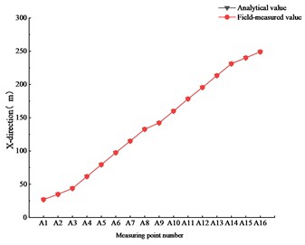
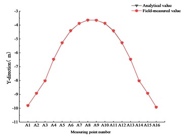
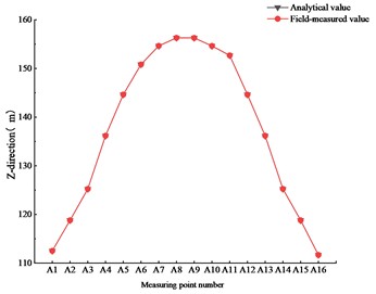
To monitor the alignment of the main arch ring after hoisting, Fig. 4 compares the alignment control results of the left and right main arches after removal of the buckle cables.
As shown in Fig. 4, the in-situ measurements of the main arch erection positions during the bridge construction process indicate that the maximum deviation between the measured and theoretical spatial positions of each segment is within 15 mm, and the overall alignment deviation is less than 0.1 %. These monitoring results satisfy the requirements of the design specifications.
Fig. 4Comparative control of main arch alignment
a)-direction (left arch)
b)-direction (left arch)
c)-direction (left arch)
d)-direction (right arch)
e)-direction (right arch)
f)-direction (right arch)
5.2. Main arch stress control results
To monitor the stress condition of the main arch ring after hoisting, Fig. 5 compares the stress control results of the left and right main arches after removal of the buckle cables.
As shown in Fig. 5, the actual stress variations of the structure are found to be generally consistent with the theoretical predictions. The maximum deviation between the measured and theoretical stresses of the main arch is 2.2 MPa, indicating that the stress monitoring results satisfy the requirements of the design specifications.
Fig. 5Comparative control of main arch stress
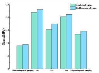
a) Stress at the upper flange of the left-side arch
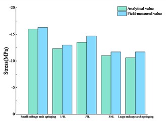
b) Stress at the lower flange of the left-side arch
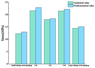
c) Stress at the upper flange of the right-side arch
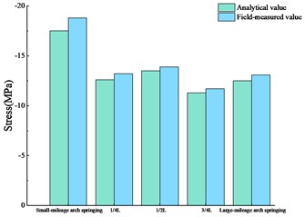
c) Stress at the lower flange of the right-side arch
5.3. Hanger cable force control results
To monitor the hanger cable forces at the completion stage, Fig. 6 presents the comparative control results of the cable forces for each hanger on both the left and right sides of the bridge. From the small mileage side to the large mileage side, the hangers on the left side are designated as Z1 to Z21, and those on the right side as Y1 to Y21.
Fig. 6Comparative control of hanger cable forces
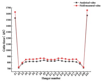
a) Hanger cable forces of the left arch
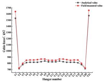
b) Hanger cable forces of the right arch
After the completion of hanger tensioning, the cable forces of all hangers on the bridge are measured. The maximum deviation between the measured and theoretical cable forces at the completion stage is 7 %, indicating that the cable force monitoring results satisfy the requirements of the design specifications.
6. Conclusions
Based on the engineering practice of a half-through steel box basket-handle arch bridge, this paper establishes a construction monitoring scheme and conducts full-process tracking monitoring of structural stresses and geometric alignment. The following conclusions are drawn:
1) The measured alignment variation of the main arch rib is generally consistent with the theoretical trend, with only minor deviations. After completion, the main arch alignment is smooth and meets the desired expectation.
2) The measured and theoretical stress variations are in good agreement, with deviations within the allowable range. The monitored sections remain in a state of full-section compression, and the maximum measured stress is far below the code-specified limit, indicating a substantial safety margin and a safe and reliable structural condition.
3) The measured hanger cable forces at the completion stage agree well with the theoretical values, with a maximum deviation of 7 %, demonstrating satisfactory control performance and compliance with the design specifications.
4) The one-time tensioning cable-stayed fastening and hanging method adopted in this study can serve as a reference for the construction of similar bridge structures.
References
-
Y. Y. Li and W. H. Dai, “Sensitivity analysis of construction parameters for half-through steel box basket-handle arch bridge,” (in Chinese), Western Transportation Science and Technology, No. 3, pp. 169–172+176, 2026, https://doi.org/10.13282/j.cnki.wccst.2026.03.044
-
J. Zhang and K. Y. Zheng, “Construction control of hanger tensioning for inclined basket-handle arch bridge,” (in Chinese), Building Structure, Vol. 52, No. S1, pp. 3191–3196, 2022, https://doi.org/10.19701/j.jzjg.22s1542
-
H. Xiao, “Structural performance analysis of long-span wide-deck steel box basket-handle arch bridge,” (in Chinese), Western Transportation Science and Technology, No. 7, pp. 150–152, 2025, https://doi.org/10.13282/j.cnki.wccst.2025.07.045
-
Y. Li, “Determination method of hanger cable forces at the completion stage for long-span steel box basket-handle tied arch bridge,” (in Chinese), Engineering Technology Research, Vol. 10, No. 9, pp. 12–14, 2025, https://doi.org/10.19537/j.cnki.2096-2789.2025.09.004
-
H. J. Feng, “Study on novel monitoring technology for construction alignment of long-span steel box basket-handle arch bridge,” (in Chinese), Progress in Steel Building Structures, Vol. 27, No. 3, pp. 103–110, 2025, https://doi.org/10.13969/j.jzgjgjz.20240401001
-
H. X. Feng, B. D. Pei, and C. X. Li, “Study on cable removal sequence in cable-stayed fastening and hanging construction for steel box arch bridges,” (in Chinese), Journal of Transportation Science and Engineering, Vol. 40, No. 3, pp. 56–64, 2024, https://doi.org/10.16544/j.cnki.cn43-1494/u.202203022024061998
-
J. J. Zhou, J. Zhang, and J. C. Wang, “Installation and construction technology of arch ribs for half-through steel box basket-handle arch bridge,” (in Chinese), Urban Roads, Bridges and Flood Control, No. 5, pp. 130–132+136+19, 2023, https://doi.org/10.16799/j.cnki.csdqyfh.2023.05.033
-
M. Yu, X. Yao, L. Wang, T. Hao, and N. Deng, “Rib alignment control of long-span arch bridge in cable-stayed buckle by multi-objective optimization,” Buildings, Vol. 14, No. 10, p. 3281, Oct. 2024, https://doi.org/10.3390/buildings14103281
-
X. Zhang, X. Ma, W. Chen, W. Xu, Y. Kang, and Y. Wu, “Constrained optimization for the buckle and anchor cable forces under one-time tension in long-span arch bridge construction,” Buildings, Vol. 15, No. 9, p. 1529, 2025, https://doi.org/10.3390/buildings15091529
-
Hou Z. et al., “Dynamic optimization method for stay cable force of long-span CFST arch bridge,” (in Chinese), Journal of Highway and Transportation Research and Development, Vol. 42, No. 12, p. 138, 2025, https://doi.org/10.3969/j.issn.1002-0268.2025.12.015
-
Q. Huang, X. Wu, Y. Zhang, and M. Ma, “Proposed new analytical method of tower load in large-span arch bridge cable lifting construction,” Applied Sciences, Vol. 12, No. 18, p. 9373, Sep. 2022, https://doi.org/10.3390/app12189373
About this article

The authors have not disclosed any funding.
The datasets generated during and/or analyzed during the current study are available from the corresponding author on reasonable request.
The authors declare that they have no conflict of interest.

