Abstract
We developed a mathematical model for the motion of a body in the trough of a vibratory conveyor that undergoes harmonic oscillations in two mutually perpendicular directions. Modelling accounts for inertial forces, gravity, reactions from the bottom and side walls of the trough, and dry friction forces between contacting surfaces. Differential equations of motion are derived for the individual stages of the body's interaction with the trough elements, and the conditions for the transition from joint motion with the trough to sliding along its surfaces are determined. Based on the developed model, the patterns of influence of amplitudes, oscillation frequencies, and friction coefficients on the velocity and nature of the body’s motion are established. To verify the adequacy of the mathematical model, we conducted experiments on a laboratory setup capable of generating harmonic oscillations of the trough in two mutually perpendicular directions. The results obtained can be utilised in the design and optimisation of vibratory conveyors for various technological applications.
Highlights
- This article develops a mathematical model for the body motion within the trough of a vibratory conveyor that undergoes harmonic oscillations in two mutually perpendicular directions.
- Differential equations of motion are derived for the distinct stages of the body's interaction with the trough elements, and the conditions for the transition from joint motion with the trough to sliding along its surfaces are determined.
- Experimental studies of the body's motion within the trough of a laboratory installation have confirmed the validity of the proposed mathematical model.
- The developed design of the vibrating conveyor can be used in practice to carry out various technological processes.
1. Introduction
The fundamental principles of vibratory conveying theory were established by Blekhman [1], who formulated the basic laws governing the motion of material on vibrating surfaces and substantiated the influence of vibration parameters on the conveying process. In [2], the results of many years of research in the field of vibrational technologies are summarised, and the prospects for their application in the development of highly efficient transport machines are demonstrated. Reference [3] investigated the motion of individual bodies on a longitudinally vibrating surface and proposed a mathematical description of the trajectory of movement as a function of vibration parameters. H. Gaberson identified the relationships of particle motion on vibratory conveyors and demonstrated the possibility of applying models of individual-body motion to describe the transport of bulk materials [4]. Hunnekens et al. investigated the process of self-alignment of solid bodies on a vibrating surface and demonstrated the possibility of controlling the direction of movement by means of friction forces [5]. M. Popov investigated the effect of normal vibrations on the magnitude of the frictional force and demonstrated that external high-frequency disturbances can significantly reduce sliding resistance [6]. The authors of [7] analysed the effect of transverse vibrations on the frictional force and identified the conditions under which the greatest reduction in contact resistance is achieved. In subsequent studies, these same authors carried out a comparative analysis of hard and soft control of friction forces and established their energy efficiency [8]. S. Kilikevičius et al. developed a method for controlling dry friction during the transport of miniature parts on a harmonically oscillating platform and experimentally confirmed its effectiveness [9]. In a subsequent paper by these authors, the transport of micro-components under sinusoidal platform oscillations was investigated, and the influence of friction control modes on the transport speed was determined [10]. Further developments in this area are presented in [11], where a mathematical model of cargo motion in the trough of an inertial conveyor under combined friction is proposed. In the authors' subsequent work, the motion of a body in the trough of a vibratory conveyor with asymmetric oscillations of the side walls was investigated, and the influence of the oscillatory process parameters on the transport patterns was established [12].
In [13], V. Korendiy et al. proposed ways to improve vibrating transport and handling machinery, analysed their kinematic and dynamic characteristics, and identified design solutions aimed at enhancing the efficiency of product transport. In subsequent research, V. Korendiy et al. developed a mathematical model of a two-mass vibratory conveyor with an electromagnetic vibrator and conducted an experimental study of its operating modes [14]. The results confirmed the adequacy of the model and demonstrated the possibility of increasing transport productivity through the rational selection of the oscillatory system's parameters.
Despite the significant number of studies carried out, most existing mathematical models describe the motion of material under uniaxial vibrations or use simplified assumptions regarding the contact interaction between the body and the trough surfaces. The issue of a body's motion within a trough undergoing harmonic oscillations simultaneously in two mutually perpendicular directions has not yet been sufficiently addressed, which necessitates the development of an appropriate mathematical model. The aim of this work is to develop a mathematical model of the motion of a body in a vibratory conveyor trough undergoing harmonic oscillations in two mutually perpendicular directions, to experimentally verify the adequacy of the proposed model, and to evaluate the effect of oscillation parameters and dry friction forces on the transport process.
2. Methodology
2.1. Theoretical research
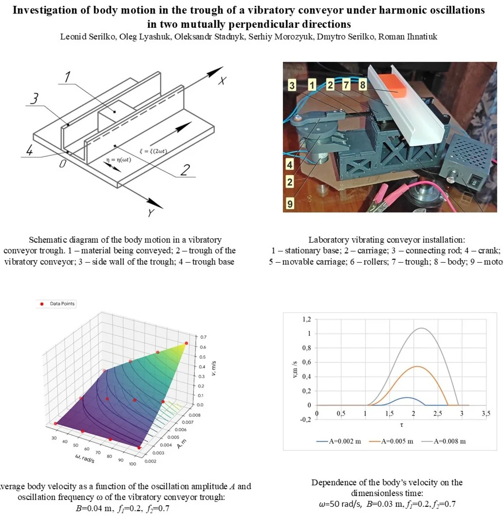
To investigate the transport process, we consider the motion of a body in the trough of a vibratory conveyor, consisting of a base and two side walls (Fig. 1).
Fig. 1Schematic diagram of the body motion in a vibratory conveyor trough: 1 – material being conveyed; 2, 3 – side walls of the trough; 4 – trough base
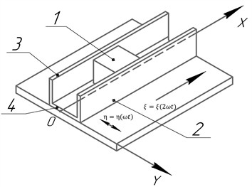
It is assumed that the trough undergoes harmonic oscillations in the plane simultaneously in two mutually perpendicular directions:
where and are the amplitudes of the oscillations along the and axes respectively, is the angular frequency of the oscillations, and is time.
Fig. 2Dependence of the velocity and acceleration of the vibratory conveyor trough on dimensionless time
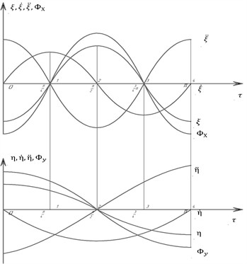
This combination of oscillations produces a periodic change in the magnitude and direction of the inertial forces, which determine the nature of the interaction between the transported body and the surfaces of the trough.
Differentiation of Eqs. (1) and (2) gives the expressions for the velocity and acceleration of the trough’s oscillations as functions of time:
Fig. 2 shows the velocity and acceleration profiles of the trough as a function of dimensionless time ().
The following forces act on the body: is gravity, is the reaction from the bottom of the trough, is the frictional force between the body and the bottom of the trough, is the reaction from the wall of the trough, is the frictional force between the body and the wall of the trough, , are inertial forces.
If the body moves in a horizontal plane, then:
where is the coefficient of friction between the body and the bottom of the trough:
where is the friction coefficient between the body and the wall of the trough. If:
then, due to the friction the body will move along with the trough until the inertial force exceeds the friction force (, – static coefficients of friction). When:
The instant , at which the inertial force equals the frictional force and the body begins to slide along the surface of wall 2 is determined under the condition:
On section () the body will move under the influence of inertial force, and the differential equation of relative motion will take the form:
Integrating the differential Eq. (14) with the initial conditions , , we obtain the dependences of the relative velocity and the movement of the body along the surface of the chute on time. At the time the relative velocity will again be equal to 0, the body is pressed against wall 3 and again moves together with the chute.
Considering the time of relative motion along the surface of the gutter and the displacement of the body , we determine the average velocity of the body.
Thus, the mathematical model developed allows us to describe all the main stages of the body's motion in the trough of a vibratory conveyor, including joint motion with the trough, the onset of sliding, movement along the bottom, contact with the side walls, and the body’s re-engagement with the trough’s motion. The analytical relationships obtained can be used to determine the parameters of the body’s motion under various conveyor operating modes and form the basis for further experimental verification of the mathematical model's adequacy.
2.2. Experimental research
To verify the results of the theoretical studies, a laboratory setup was developed; its schematic diagram is shown in Fig. 3. It consists of a stationary base 1 and a carriage 2, which is mounted so as to be able to move in the horizontal plane along the -axis by means of a connecting rod 3 hinged to a crank 4.
Fig. 3Laboratory vibrating conveyor installation: 1 – stationary base; 2 – carriage; 3 – connecting rod; 4 – crank; 5 – movable carriage; 6 – rollers; 7 – trough; 8 – body; 9 – motor
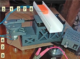
The base 1 has grooves on its sides, into which the movable carriage 5 is guided by rollers 6. A trough 7 is rigidly attached to the movable carriage, along which the body 8 moves. The grooves in the base are designed such that, as the rollers 6 move along them, the carriage performs harmonic oscillations along the -axis. As the crank 4 rotates, the trough 7 performs mutually perpendicular movements, the amplitude of which depends on the radius of the crank and the dimensions of the grooves in the base 1. In our case, the amplitude of the oscillations along the -axis was 2.5 mm, and along the -axis 22.5 mm. The rotational movement of the crank 4 is driven by motor 9, the rotational speed of which can be varied. A plastic block measuring 50×35×15 mm is used as the transported object. To vary the coefficients of friction between the surface of the transported object and the trough wall, strips of different materials were affixed.
The coefficients of static friction of the object against the surfaces of the trough floor and walls were determined using the inclined plane method. The time taken for the body to travel along the trough surface was determined using video recording.
3. Results and discussion
3.1. Results of the theoretical research
The results of theoretical studies of the average velocity of the body moving along the trough surface are shown in Fig. 4.
Fig. 4Average body velocity as a function of the oscillation amplitude A and oscillation frequency ω of the vibratory conveyor trough: B= 0.04 m, f1= 0.2, f2= 0.7
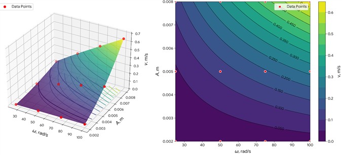
The graphs indicate that the average velocity of the body, and consequently the productivity of the vibratory conveyor, is significantly influenced by the amplitude and frequency of the longitudinal oscillations. Thus, at 85 rad/s, 0.005 m, 0.22 m/s, whilst at 85 rad/s, 0.008 m, 0.55 m/s. The results of theoretical studies determining the dependence of the relative velocity of a body moving along the surface of a vibratory conveyor trough on the dimensionless time (Fig. 5).
Fig. 5Dependence of the body’s velocity on the dimensionless time: B= 0.03 m, f1= 0.2, f2= 0.7
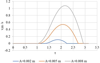
a) ω=50 rad/s
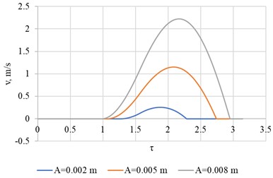
b) 100 rad/s
Analysis of the obtained relationships leads to the conclusion that the relative motion of the body along the surface of the trough occurs over the time interval .
3.2. Results of the experimental research
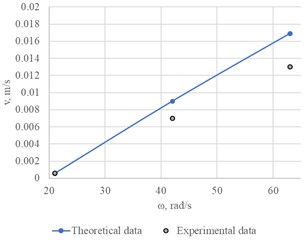
Fig. 6 shows the graphical dependences of the average speed of movement of the body in the trough of the vibrating conveyor on the frequency of oscillations obtained experimentally. The maximum relative error between the theoretical and experimental values of the body’s average speed is 23 %. The obtained experimental values of the average velocity of the body are lower than the theoretical ones, since in the mathematical modeling of the body motion in the conveyor chute we assumed that the coefficients of static and sliding friction between the body and the bottom and walls of the conveyor chute are the same.
Fig. 6Experimental values of the average body velocity as a function of the oscillation frequency ω of the vibratory conveyor trough: A= 0.0025 m, B= 0.0225 m, f1= 0.26, f2= 0.57
4. Conclusions
This paper considers the problem of body motion in the chute of a vibrating conveyor that performs both longitudinal and transverse oscillations, with the frequency of longitudinal oscillations of the chute being twice the frequency of transverse oscillations. As a result of the mathematical modeling of the body’s motion, the dependences of the body’s motion velocity in the conveyor chute on both the kinematic parameters (frequency and amplitude of oscillations) and the friction coefficients of the body’s sliding along the chute surface were obtained. Experimental studies conducted on the developed laboratory installation confirmed the results of mathematical modeling of body motion using the proposed method of vibration displacement. The agreement between theoretical and experimental values of body motion in a vibration trough exceeds 77 %.
References
-
I. I. Blekhman, L. I. Blekhman, L. A. Vaisberg, and V. B. Vasilkov, “Energy performance of vibrational transportation and process machines,” in Lecture notes in mechanical engineering, Singapore: Springer Nature Singapore, 2020, pp. 29–46, https://doi.org/10.1007/978-981-15-8049-9_2
-
L. Vaisberg, “Vibration technology research achievements of the Mekhanobr scientific school and their practical implementation,” Vibroengineering Procedia, Vol. 25, pp. 76–82, Jun. 2019, https://doi.org/10.21595/vp.2019.20820
-
D. Reznik, J. Canny, and K. Goldberg, “Analysis of part motion on a longitudinally vibrating plate,” in Proceedings of the 1997 IEEE/RSJ International Conference on Intelligent Robot and Systems. Innovative Robotics for Real-world Applications. IROS ’97, Vol. 1, pp. 421–427, 2002, https://doi.org/10.1109/iros.1997.649098
-
H. A. Gaberson, “Particle motion on oscillating conveyors-part 2. practical solutions to the equations of motion and the extension of the theory to beds of granular material,” Journal of Engineering for Industry, Vol. 94, No. 1, pp. 57–63, 1972, https://doi.org/10.1115/1.3428155
-
B. G. B. Hunnekens, R. H. B. Fey, A. Shukla, and H. Nijmeijer, “Vibrational self-alignment of a rigid object exploiting friction,” Nonlinear Dynamics, Vol. 65, No. 1-2, pp. 109–129, Nov. 2010, https://doi.org/10.1007/s11071-010-9878-0
-
M. Popov, V. L. Popov, and N. V. Popov, “Reduction of friction by normal oscillations. I. influence of contact stiffness,” Friction, Vol. 5, No. 1, pp. 45–55, 2017, https://doi.org/10.1007/s40544-016-0136-4
-
J. Benad, K. Nakano, V. L. Popov, and M. Popov, “Active control of friction by transverse oscillations,” Friction, Vol. 7, No. 1, pp. 74–85, Mar. 2018, https://doi.org/10.1007/s40544-018-0202-1
-
J. Benad, M. Popov, K. Nakano, and V. L. Popov, “Stiff and soft active control of friction by vibrations and their energy efficiency,” Forschung Im Ingenieurwesen, Vol. 82, No. 4, pp. 331–339, 2018, https://doi.org/10.1007/s10010-018-0281-1
-
S. Kilikevičius, A. Fedaravičius, V. Daukantienė, K. Liutkauskienė, and L. Paukštaitis, “Manipulation of miniature and microminiature bodies on a harmonically oscillating platform by controlling dry friction,” Micromachines, Vol. 12, No. 9, p. 1087, Sep. 2021, https://doi.org/10.3390/mi12091087
-
S. Kilikevičius, A. Fedaravičius, V. Daukantienė, and K. Liutkauskienė, “Analysis on conveying of miniature and microparts on a platform subjected to sinusoidal displacement cycles with controlled dry friction,” Mechanics, Vol. 28, No. 1, pp. 38–44, 2022, https://doi.org/10.5755/j02.mech.28195
-
L. Serilko, O. Lyashuk, D. Chasov, D. Serilko, and R. Ihnatiuk, “Body movement along the surface of an inertial conveyor chute under combined friction,” Journal of Engineering Sciences, Vol. 12, No. 1, pp. D1–D8, Apr. 2025, https://doi.org/10.21272/jes.2025.12(1).d1
-
L. Serilko, O. Lyashuk, O. Stadnyk, D. Serilko, D. Mironov, and S. Morozyuk, “Investigation of body motion in the trough of a vibratory conveyor with asymmetric oscillations of walls,” Vibroengineering Procedia, Vol. 60, pp. 24–31, Dec. 2025, https://doi.org/10.21595/vp.2025.25234
-
V. Korendiy, V. Shenbor, O. Havrylchenko, and V. Brusentsov, “Improvement of vibratory conveying and manipulating machines,” Scientific Journal of the Ternopil National Technical University, Vol. 92, No. 4, pp. 68–82, 2019, https://doi.org/10.33108/visnyk_tntu2018.04.068
-
V. Korendiy, O. Kachur, I. Hurey, R. Predko, R. Palash, and O. Havrylchenko, “Modelling and experimental investigation of the vibratory conveyor operating conditions,” Vibroengineering Procedia, Vol. 47, pp. 1–7, Dec. 2022, https://doi.org/10.21595/vp.2022.23057
About this article

The authors have not disclosed any funding.
The datasets generated during and/or analyzed during the current study are available from the corresponding author on reasonable request.
The authors declare that they have no conflict of interest.

