Abstract
Distributed drive electric vehicles face vibration and noise challenges due to the coupling of high-frequency electromagnetic excitation, time-varying meshing stiffness, and thermal deformation, forming a typical electromechanical-thermal multi-field coupled vibration. A systematic investigation into this coupling mechanism and suppression strategy is presented. An electromechanical-thermal multi-field dynamic model is established to reveal multi-field interactions. A hierarchical collaborative suppression method is proposed: structural optimization reduces transmission vibration; control-level model predictive control with harmonic current injection mitigates electromagnetic excitation; thermal-level coolant regulation suppresses thermally induced vibration. Dynamometer tests show that the proposed method reduces critical component vibration by 5 dB(A), significantly improving NVH performance. This study offers a complete technical pathway for low-noise design from mechanism analysis to suppression implementation.
1. Introduction
Distributed electric drive systems offer major advantages for vehicle electrification but present serious NVH problems due to their high-power density and integration [1]. The key reason lies in the coupling among mechanical, electrical, and thermal fields [2].
Electromagnetically, motors generate complex force waves from air-gap field harmonics [3, 4]. Mechanically, time-varying stiffness and errors in dual-planetary transmissions produce vibrations that couple with electromagnetic excitations, creating modulation effects that amplify the response [5-6]. Thermally, high loads cause temperature rises and deformation, altering meshing conditions and stiffness via thermo-elastic coupling [7, 8].
Because the three fields interact spatially and temporally, conventional single-field analyses cannot capture this multi-field mechanism, nor can passive measures adequately address it [9]. Therefore, investigating electromechanical-thermal coupling and developing active suppression methods are essential for improving NVH [10]. This paper addresses the problem by establishing a coupled dynamic model, proposing a hierarchical collaborative suppression method, and validating it through simulations and dynamometer tests.
2. Electromechanical-thermal coupling modeling of distributed electric drive systems
2.1. Research object and coupling mechanism
Since the subject of this paper is an innovative distributed electric drive system combining a permanent magnet motor, a dual-planetary gear train, and a final reduction gear, its configuration is shown in Fig. 1.
Fig. 1Schematic of the distributed electric drive system configuration
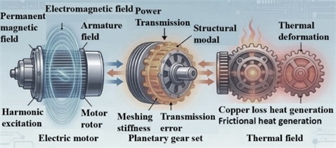
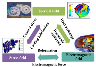
The three fields interconnect: electromagnetic force waves act on structures; mechanical deformation alters the air gap, affecting electromagnetic distribution; thermal changes modify material properties; and power loss links electromagnetic and thermal fields.
2.2. Electromagnetic-mechanical-thermal multi-field coupled dynamic model
2.2.1. Electromagnetic field model
The electromagnetic field of the permanent magnet motor can be described by Maxwell's equations. Based on solving the time-varying electromagnetic field using the finite element method, the radial electromagnetic force density in the air gap is expressed as:
where and are the radial, tangential components of the air-gap flux density, respectively, and is the vacuum permeability.
Since the current time harmonics caused by the inverter supply are known, it is natural to write the stator current as follows:
where is the harmonic order and is the fundamental electrical angular frequency. The interaction between time and spatial harmonics produces electromagnetic force wave components with orders and amplitudes. These force waves, which exert force density on the stator tooth surfaces, serve as the primary excitation source for structural vibrations.
2.2.2. Mechanical field model
The dual-planetary gear compound transmission system can be simplified as a multi-degree-of-freedom lumped parameter model, and its dynamic equation is given as:
where is the generalized displacement vector; , , and are the mass matrix, damping matrix, and time-varying stiffness matrix of the system, respectively; is the electromagnetic force vector; and is the external excitation vector.
The time – varying meshing stiffness of the gear pair can be represented as a Fourier series:
where represents the meshing angular frequency, denotes the average stiffness, and indicates the amplitude of the th harmonic.
2.2.3. Thermal field model
The heat conduction equation governs the system’s temperature field distribution:
where is the heat source term per unit volume, which primarily includes copper loss, iron loss and mechanical loss. The density is represented by , is the specific heat capacity, and is the thermal conductivity.
2.3. Coupled dynamic equations and decoupling strategy
Since the models of the three physical fields are integrated, it is natural to write down the complete coupled dynamic equations of the system:
FEM for electromagnetic field, Newmark- integration for mechanical response, and finite difference for thermal field, with iterative data exchange at each time step.
3. Electromechanical-thermal coupling vibration mechanism analysis
3.1. Electromechanical-thermal coupling mechanism
Coupled vibration analysis is naturally based on the mutual feedback between physical fields: electromagnetic forces induce mechanical vibration, and structural deformation affects the electromagnetic forces, while temperature changes modify material properties, thereby altering both mechanical stresses and electromagnetic parameters. Hence Figs. 2 and 3 show the system schematic and the coupling mechanism. A co-simulation platform with an appropriate data transfer interface is used to perform coupled iterative calculations, guaranteeing convergence and stability of the multi-field interaction.
3.2. Electromechanical-thermal coupling vibration analysis
Vibration orders of the motor, gears, and bearings are analyzed to assess superposition risk. The motor exhibits orders of 8, 40, and 56; gear meshing orders range 3.6-36.9; bearing orders range 3.77-22.36. The motor's fundamental electromagnetic frequency is 400-533 Hz, while gear and bearing meshing frequencies are 1850-3075 Hz. No overlap among orders or frequencies is observed under operating conditions, indicating no three-way resonance coupling.
Fig. 2Schematic of the electric drive system
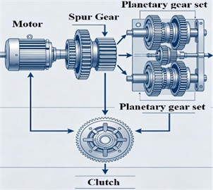
Fig. 3Electromechanical-thermal coupling mechanism of the electric drive system
The free modal analysis provides the fundamental frequencies of the core components P1 sun gear at 9338 Hz, P2 sun gear at 595 Hz, and G1 final reduction gear at 3597 Hz. These all avoid typical meshing frequencies, confirming no resonance risk.
Table 1First-order modal frequencies of core components
Component | P1 sun gear | P2 sun gear | G1 final gear |
First-order modal frequency | 9338 Hz | 595 Hz | 3597 Hz |
First-order mode shape | 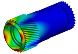 | 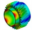 |  |
Fig. 4Contact stress of gear
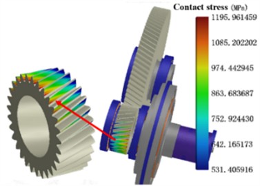
Fig. 5Transmission error of gear
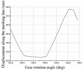
Considering both electromagnetic excitation and thermal effects, the contact stress and transmission error of the gears are obtained through analysis. Fig. 4 shows the contact stress of Gear 1, with a maximum value of 1196 MPa. Fig. 5 presents the transmission error of Gear 1, with a peak-to-peak value of 5.2 μm. These results indicate the potential for further optimization.
4. Hierarchical collaborative vibration suppression method
From the foregoing mechanism analysis, a hierarchical collaborative vibration suppression method framework is naturally and logically proposed in Fig. 6, together with a clear statement that the method performs collaborative suppression along the three dimensions: structural, control, and thermal management.
Control-level harmonic injection augments MPC with harmonic states. Current reference combines fundamental and 5th/7th/11th/13th harmonics, optimized to minimize force distortion. MPC tracks all references, summing compensation with feedforward before inverter output to suppress specific-order force-wave vibrations. At the thermal management level, coolant flow rate is regulated to achieve precise temperature control of critical components. At the structural level, profile and lead adjustments are applied to reduce the maximum tooth surface load of the gears. Table 2 provides a summary of the gear micro-modification technique. Changes are implemented in both the profile and lead directions.
Fig. 6Framework of the hierarchical collaborative vibration suppression method
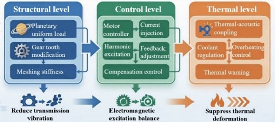
Table 2Gear micro-modification parameters
Modification parameter | Value before optimization | Value after optimization |
Lead slope | 1 μm | 3.5 μm |
Lead crown | 3 μm | 10 μm |
Involute slope | 1 μm | 3.5 μm |
Involute crown | 3 μm | 10 μm |
Parabolic tip relief | 2 μm | 6.5 μm |
Transmission error | 5.2 μm | 1.93 μm |
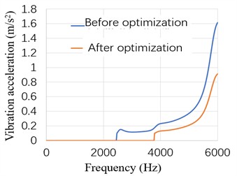
A genetic algorithm with 1000 iterations was employed to optimize the gear profile and lead modifications, compensating for structural deformation under load and reducing transmission error and meshing impact. Objective: , where is the dynamic transmission error and is the housing vibration acceleration. Constraints: 1200 MPa. Convergence: objective change < 10⁻3 over 50 generations. The resulting modification parameters are presented in Table 2. As shown in Figs. 7 and 8, after optimization, the dynamic transmission error is reduced to within 1.5 μm, and the housing vibration acceleration decreases by 0.15 m/s2 compared to the baseline, demonstrating the effectiveness of the optimization.
Fig. 7Dynamic transmission error before and after gear modification
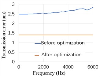
Fig. 8Vibration acceleration amplitude of the housing before and after gear modification
5. Experimental validation
A test bench for the distributed electric drive system was constructed, with a dynamometer applied to simulate vehicle driving conditions. The tests were performed under typical operating conditions, and the collected data were averaged for analysis. As shown in Fig. 9, the accuracy of the coupled model and the proposed vibration suppression method is validated.
Fig. 9Vibration and noise test results of the gear pair before and after optimization
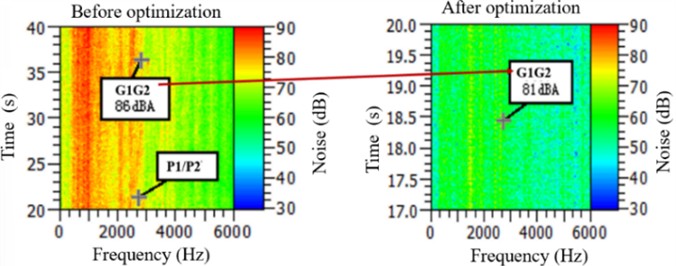
Since the measured noise level is 86dB before optimization and 81 dB after, a 5 dB reduction is achieved, and the temperature monitoring data clearly show that the adopted thermal management strategy kept winding temperature below 105 °C and magnet temperature below 80 °C, hence thermally induced vibration amplification is effectively suppressed.
6. Conclusions
The main conclusions may be neatly and clearly summarized as follows.
1) The three-field coupling vibration mechanism of the distributed electric drive system, in which electromagnetic, mechanical, and thermal couplings are all taken into account, has been clearly presented.
2) A hierarchical collaborative vibration suppression method which combines the structural, control, and thermal management levels is presented.
3) From the test results it is clearly and convincingly shown that the proposed three-level collaborative suppression method suppresses vibration response at the transmission components by 5 dB (A).
Steady-state thermal validation is confirmed, while transient data and on-road AI suppression remain future work. The method applies to other distributed configurations.
References
-
X. Sun, Z. Shi, Y. Cai, G. Lei, Y. Guo, and J. Zhu, “Driving-cycle-oriented design optimization of a permanent magnet hub motor drive system for a four-wheel-drive electric vehicle,” IEEE Transactions on Transportation Electrification, Vol. 6, No. 3, pp. 1115–1125, Jul. 2020, https://doi.org/10.1109/tte.2020.3009396
-
Z. Zhao, H. Taghavifar, H. Du, Y. Qin, M. Dong, and L. Gu, “In-wheel motor vibration control for distributed-driven electric vehicles: a review,” IEEE Transactions on Transportation Electrification, Vol. 7, No. 4, pp. 2864–2880, Apr. 2021, https://doi.org/10.1109/tte.2021.3074970
-
L. Alberti, E. Fornasiero, N. Bianchi, and S. Bolognani, “Rotor losses measurements in an axial flux permanent magnet machine,” IEEE Transactions on Energy Conversion, Vol. 26, No. 2, pp. 639–645, Feb. 2011, https://doi.org/10.1109/tec.2010.2096818
-
T. Liu, W. Zhao, and J. Ji, “Review of computational methods for electromagnetic vibration and noise in inverter-fed permanent magnet synchronous machines,” Acta Aeronautica Et Astronautica Sinica, Vol. 47, No. 1, p. 332127, 2026.
-
A. Kahraman, “Free torsional vibration characteristics of compound planetary gear sets,” Mechanism and Machine Theory, Vol. 36, No. 8, pp. 953–971, Jul. 2002, https://doi.org/10.1016/s0094-114x(01)00033-7
-
S. Dhouib, R. Hbaieb, F. Chaari, M. S. Abbes, T. Fakhfakh, and M. Haddar, “Free vibration characteristics of compound planetary gear train sets,” Proceedings of the Institution of Mechanical Engineers, Part C: Journal of Mechanical Engineering Science, Vol. 222, No. 8, pp. 1389–1401, Aug. 2008, https://doi.org/10.1243/09544062jmes870
-
S. Mo et al., “The thermo-mechanical coupling dynamic analysis of gear-rotor-bearing system with multiple dynamic clearances,” Mechanism and Machine Theory, Vol. 215, p. 106169, Aug. 2025, https://doi.org/10.1016/j.mechmachtheory.2025.106169
-
Y. Lu, J. Li, R. Qu, D. Ye, and H. Lu, “Electromagnetic force and vibration study on axial flux permanent magnet synchronous machines with dual three-phase windings,” IEEE Transactions on Industrial Electronics, Vol. 67, No. 1, pp. 115–125, Jan. 2019, https://doi.org/10.1109/tie.2018.2890494
-
Z. Song et al., “Torque distribution strategy for multi-PMSM applications and optimal acceleration control for four-wheel-drive electric vehicles,” Journal of Dynamic Systems, Measurement, and Control, Vol. 142, No. 2, p. 021001, 2020, https://doi.org/10.1115/1.4045321
-
J. Guanetti, Y. Kim, and F. Borrelli, “Control of connected and automated vehicles: state of the art and future challenges,” Annual Reviews in Control, Vol. 45, pp. 18–40, May 2018, https://doi.org/10.1016/j.arcontrol.2018.04.011
About this article

This work is supported by the Open Fund of State Key Laboratory of Engine and Powertrain System (skleps-sq-2024-079), the Science and Technology Plan of Inner Mongolia (2025YFDZ0020).
The datasets generated during and/or analyzed during the current study are available from the corresponding author on reasonable request.
The authors declare that they have no conflict of interest.

