Abstract
To achieve the dual improvement of weight reduction and vibration damping of brake discs on the premise that heat transfer performance and strength performance were not attenuated, a multi-objective optimization scheme based on the response surface algorithm was proposed. Firstly, considering the influence of thermal stress on the natural frequency of brake discs, a thermal-structural-modal coupling analysis model of the braking system was established. The transient temperature field, transient stress field and pre-stress modal response characteristics were obtained, and the accuracy of the finite element model was verified through temperature and modal tests. Secondly, experimental design was carried out based on Central Composite Design (CCD), and the quadratic response surface method was introduced to construct a surrogate model, so as to realize the mathematical expression of natural frequency, peak temperature, peak stress and mass. Finally, a multi-dimensional optimization mathematical model was constructed. With the minimum mass as the objective, combined with the Sequential Quadratic Programming (SQP) algorithm, the first-order natural frequency was optimized to the range of 1400-1800 Hz on the premise that the peak thermal stress was not increased. The research results showed that under the condition of meeting the multi-objective optimization requirements, the mass of the brake disc could be reduced by more than 3.5 %. The proposed thermal-structural-modal coupling analysis model solved the problem that the traditional modal calculation had a large deviation from the actual boundary conditions. The applied quadratic response surface surrogate model realized multi-objective collaborative optimization, which had important engineering value for improving the NVH performance of automobiles, alleviating the continuous excitation of the brake disc friction pair and the modal coupling resonance between components, and promoting the development of automotive lightweighting and intelligentization.
Highlights
- Compared to existing research, a thermo-structural-modal coupled analysis model of the brake system is established by considering the influence of thermal stress on the natural frequency of the brake disc.
- Compared to existing research, the quadratic response surface methodology is introduced into the multi-objective optimization scenario of disc brakes to construct a highly reliable surrogate model.
- Compared to existing research, a multi-dimensional optimized mathematical model is constructed.
1. Introduction
As the automotive industry undergoes a profound transformation towards intelligentization and high-end development, the overall vehicle ride comfort and NVH (Noise, Vibration and Harshness) performance have emerged as core evaluation criteria for judging the comprehensive quality of automobiles [1-3]. Under actual braking conditions, the continuous excitation of the brake disc friction pair and the modal coupling resonance between components are extremely prone to inducing vibration and noise hazards such as high-frequency brake squeal, steering wheel shudder and body chatter [4-6]. These problems not only drastically degrade the driving and riding experience; the alternating stresses generated by long-term resonance also accelerate the fatigue damage of the brake disc and shorten the service life of components. Meanwhile, the braking process is accompanied by intense heat conduction and thermal stress concentration, where the heat transfer efficiency and structural strength of the brake disc directly determine braking stability and safety. Moreover, the automotive industry’s stringent requirements for the lightweighting of unsprung mass further exacerbate the contradiction in the collaborative optimization of four critical indicators: vibration and noise reduction, heat dissipation performance, structural strength and lightweight design. How to realize the dual enhancement of weight reduction and vibration damping for brake discs on the premise of guaranteeing no attenuation in heat transfer and strength performance has become an urgent technical bottleneck to be conquered in the current research and development of automotive braking systems.
At present, experts and scholars have carried out extensive research on the vibration and noise, structural optimization and thermal characteristic analysis of disc brakes, and achieved fruitful outcomes in the fields of brake disc modal simulation, vibration damping structure improvement, heat dissipation flow field optimization and so on. Representative studies are presented as follows: Fahimeh [7] obtained the modal parameters of the brake disc-pad assembly under different braking pressures via experimental modal analysis, and accordingly constructed and revised the finite element model of the brake disc with contact characteristics. This research realized the accurate prediction of the dynamic characteristics of the braking system, providing a high-precision simulation foundation for the analysis of brake vibration and noise and structural optimization. Gräbner [8] employed the complex eigenvalue analysis in Abaqus to simulate the effect of damping on the unstable modes of the system. By comparing the simulation results with the test data, the effectiveness of damping measures was verified, and a combined test-simulation approach for the damping evaluation of brake squeal was established. Agrawal [9] adopted an integrated method of analytical calculation and experimental test to systematically investigate the heat transfer characteristics, temperature distribution and variation law of thermal stress of ventilated disc brakes during operation. On the basis of the analytical results, the structure of ventilated disc brakes was optimized to enhance their thermal performance, which offers theoretical support and experimental verification for the efficient design of ventilated disc brakes.
Currently, research focusing on multi-objective collaborative optimization still presents significant shortcomings and fails to meet the demands of practical engineering applications. Most studies solely concentrate on the optimization of brake vibration reduction, noise suppression or lightweight design, while neglecting the constraints of brake heat transfer efficiency and structural stress. Consequently, the optimized schemes are prone to problems such as deteriorated heat dissipation, insufficient strength and degraded thermal stability, rendering them inapplicable for engineering practice [10-12]. The application of response surface methodology in brake optimization is mostly limited to single performance indicators, and a high-precision surrogate model that simultaneously considers vibration response, modal characteristics, heat transfer performance, structural stress and lightweight property has not yet been established, which hinders efficient optimization seeking under multiple constraints. The differences between this study and existing mainstream brake disc optimization research are mainly reflected in four core aspects. In terms of coupling level, most existing studies adopt single-field or two-field simplified analysis to independently analyze modal vibration, thermal characteristics or structural stress, ignoring the coupling effect of thermal stress on brake disc modal characteristics and leading to obvious simulation deviation, while this paper constructs a complete thermo-structural-modal multi-field coupled analysis model to fully capture the multi-field interactive correlation and eliminate calculation errors caused by simplified boundary conditions. In terms of objective set, previous researches mainly focus on single-objective optimization including independent vibration and noise reduction, thermal performance improvement or structural lightweighting, which cannot balance multiple core braking performances, whereas this study implements multi-objective collaborative optimization to synchronously achieve lightweight design and vibration suppression while guaranteeing reliable thermal and structural performance. In terms of constraint formulation, existing studies adopt single and one-sided constraint conditions that only limit individual performance indicators, easily causing attenuation of other unconstrained performances after optimization; by contrast, this paper establishes multi-dimensional composite constraint equations, taking peak temperature and peak stress as rigid constraints to maintain heat dissipation and structural strength, and combining natural frequency range constraints to ensure dynamic stability. In terms of optimization strategy, traditional optimization relies on simple test verification or conventional finite element simulation, and response surface methods are only applied to single-performance fitting without multi-performance coupled high-precision surrogate models, resulting in low optimization efficiency and accuracy, while this paper innovatively introduces quadratic response surface methodology into brake multi-objective optimization and builds a high-precision surrogate model covering natural frequency, peak temperature, peak stress and structural mass to realize efficient and accurate multi-constraint collaborative optimization.
Based on the above comprehensive comparison, this paper breaks through the limitations of traditional single-field analysis, single-objective optimization and simple constraint strategies in existing studies via multi-field coupling analysis and multi-dimensional collaborative optimization, effectively solving the engineering problems of unbalanced comprehensive performance and poor practicability of optimized brake disc structures. The main innovations of this paper are embodied as follows:
(1) Compared to existing research, a thermo-structural-modal coupled analysis model of the brake system is established by considering the influence of thermal stress on the natural frequency of the brake disc, which solves the problem of large deviation between traditional modal calculation results and actual boundary conditions.
(2) Compared to existing research, the quadratic response surface methodology is introduced into the multi-objective optimization scenario of disc brakes to construct a highly reliable surrogate model, realizing the mathematical expression of natural frequency, peak temperature, peak stress and mass.
(3) Compared to existing research, a multi-dimensional optimized mathematical model is constructed. Without increasing the peak temperature and peak stress, the mass is reduced within the optimal range of natural frequency, thus achieving efficient multi-objective collaborative optimization.
2. Establishment and analysis of thermal-structural-modal coupling model
2.1. Load and operating parameters of braking system
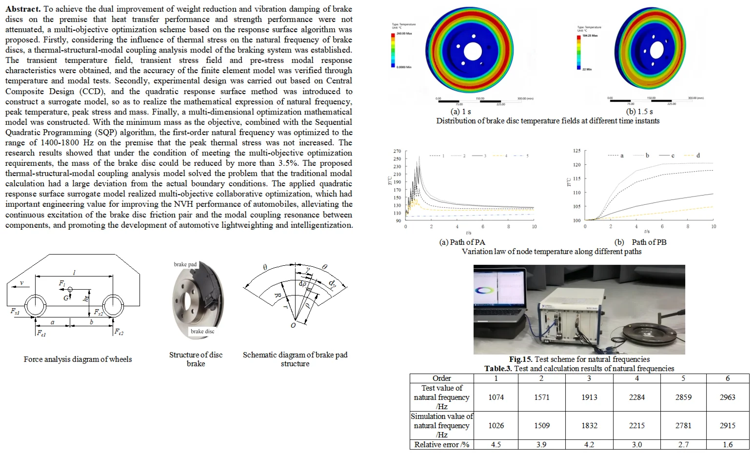
Assuming that a fully loaded vehicle brakes on a smooth and relatively hard road surface, the force analysis diagram of the wheel is established as shown in Fig. 1.
Fig. 1Force analysis diagram of wheels
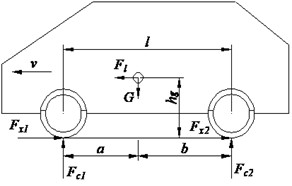
Fig. 2Structure of disc brake
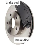
Fig. 3Schematic diagram of brake pad structure
According to the principle of moment equilibrium, the moment equilibrium equations for the front and rear wheels can be derived as:
where denotes the supporting force of the front wheels, denotes the supporting force of the rear wheels, is the height of the center of mass, is the gravity of the vehicle, is the wheelbase of the vehicle, is the distance from the center of mass to the front axle, is the distance from the center of mass to the rear axle, is the driving speed, and is time.
When the vehicle is fully loaded, / ≈ 2 and ≈ 0.9 m. Therefore, the maximum braking force on the front axle can be obtained as:
where denotes the pavement adhesion coefficient.
The structure of the disc brake is illustrated in Fig. 2, which consists of brake pad and brake disc, and the main dimensions of friction pairs is shown in Table 1. The structural parameter model of the brake pad is established as shown in Fig. 3, based on which the differential frictional torque per unit area can be derived as:
where is the friction coefficient, is the pressure per unit friction surface, is the unit friction area, is the radial dimension of the brake pad.
Table 1Main dimensions of friction pairs
Friction pairs | Inner diameter / mm | Outer diameter / mm | Thickness / mm | wrap angle / ° |
Brake disc | 160 | 330 | 25 | 360 |
Brake pad | 175 | 284 | 13 | 66.5 |
According to the braking principle, the sliding friction between the brake disc and the brake pad is a typical form of dry friction. As indicated by the solid friction mechanism, the generation of friction force between friction pairs is primarily attributed to three effects: interlocking effect, adhesion effect and ploughing effect. Owing to the certain surface roughness of the friction pair, relative sliding will induce a specific mechanical deformation resistance in the asperities of the contact surfaces, which is defined as the interlocking friction resistance. Based on the mechanical-molecular interaction theory, the friction force produced by the interlocking effect can be expressed as:
where is the interlocking friction resistance, is the interlocking area of the contact surfaces, is the tangential stress, is the normal load coefficient, is the compressive stress, is an exponent approaching unity.
Under the action of braking pressure, the contact stress sustained by the asperities on the friction pair surfaces will exceed the compressive yield strength, thereby inducing plastic deformation and adhesion at the contact points. The resistance generated by the plastic deformation of the adhesion junctions is referred to as the adhesive friction force , which can be calculated as:
where is the actual contact area of friction under sliding conditions, is the adhesive shear strength.
When the brake is in operation, the surfaces of the friction pair will inevitably shed or trap some hard particles. Under the action of braking pressure, these particles exert a ploughing effect on the surfaces. There are various types of ploughing models. Taking the conical model with a half-angle as an example, when the penetration depth of the hard particles is , the frictional resistance caused by the ploughing effect is given by:
where is the projected area of the ploughing model on the vertical plane, is the radius of the conical model, is the yield strength of the softer material.
2.2. Mathematical description of the coupling model
To reveal the coupling mechanism of thermal, structural and modal fields during the braking process of disc brakes, and to tackle key problems such as thermal fade, vibration and noise, the thermal-structure-modal coupling analysis model for disc brakes are proposed, which can fully describe the interactions among temperature, stress and modal characteristics [13, 14].
For the coupled calculation of stress and modal characteristics, it is assumed that the structure is initially subjected to the static prestress , and the stress is coupled with the modal equation via the geometric stiffness (stress stiffness) , whose expression is given as:
where is the generalized modal coordinate, is the mass matrix, is the damping matrix, is the elastic stiffness matrix, is the stress stiffness matrix, which is also the linear function of the initial stress , is the external load.
To facilitate the description of the thermo-stress coupling problem, the two-dimensional plane is adopted as the analytical domain, and the physical constitutive equations correlating stress, strain and temperature are expressed as follows:
where is the temperature, and are the normal strains, is the shear strain, and are the normal stresses, is the shear stress, is the Poisson’s ratio, is the modulus of elasticity, is the thermal expansion coefficient.
During braking, a large amount of heat flux generated by friction is transferred and diffused through the brake disc. Parameters including heat transfer efficiency, temperature distribution uniformity, material thermal conductivity and structural topology determine the distribution pattern of the internal temperature field. Non-uniform heat transfer results in drastic temperature gradients, which induce thermal stress. When superimposed with the mechanical stress generated by braking pressure, a complex stress field is formed, and an irrational structural design will further exacerbate stress concentration. There is an intrinsic correlation between stress distribution and natural frequency. The natural frequency of the brake disc is governed by factors such as mass distribution and stiffness properties, while the stress state modifies the equivalent stiffness of the structure. Tensile stress enhances the structural stiffness and thus elevates the natural frequency, whereas compressive stress reduces the stiffness and lowers the frequency; extreme compressive stress may even trigger structural buckling. Non-uniform stress distribution gives rise to spatial discrepancies in stiffness, which changes the intervals of each order of natural frequencies and induces mode localization. Besides, the periodic variation of dynamic thermal stress causes nonlinear fluctuations in natural frequencies, forming a closed-loop coupling of heat-stress-natural frequency. If the natural frequency falls within the range of the excitation frequency under braking conditions, resonance is likely to be triggered, leading to intensified vibration and noise. The superposition of alternating stress and thermal stress accelerates the propagation of fatigue cracks, and may even result in the cracking and failure of the brake disc. Therefore, collaborative optimization of the brake disc is required.
2.3. Establishment of finite element model
The three-dimensional geometric model of the disc brake is established, as shown in Fig. 4. Technological features that have no effect on heat transfer and structural force transmission, such as the threads of bolt holes and decorative chamfers on the outer edge, are removed during modeling. Meanwhile, geometric repair is carried out in SpaceClaim to adapt to the thermal-structural coupling analysis, in which free edges, interfering surfaces and sharp corners are eliminated to prevent interpolation errors in data transmission [15]. Named selections including the frictional contact surfaces and constraint mounting surfaces are predefined, which contributes to the efficient application of boundary conditions. In terms of mesh generation, hexahedral swept meshes are adopted for the core contact zones of the friction pair, and four layers of elements are divided along the thickness direction to accurately capture the temperature and stress gradients. A hybrid mesh composed of hexahedral and tetrahedral elements with a size of 2 mm is utilized for secondary critical regions such as the brake disc body and the steel back plate, while free tetrahedral meshes with a size of 5 mm are employed for non-critical regions including the hub mounting zone. The contact pairs are defined with CONTA174/TARGE170 elements, and the thermal contact conduction function is activated. The mesh generation result is displayed in Fig. 5, and the final number of elements and nodes is determined to be 680211 and 842565, respectively.
Fig. 4The three-dimensional geometric model
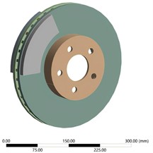
Fig. 5Mesh division results
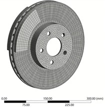
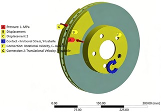
The transient thermomechanical strong coupling analysis of the disc brake is conducted in ANSYS Workbench. A triangular bidirectional coupling data stream is constructed by dragging the Transient Structural, Transient Thermal and System Coupling components in the project setup, and the data interconnection among the three fields is completed. For contact configuration, frictional contact pairs between the brake disc and brake pads are created in the structural field; the frictional contact type and the augmented Lagrange contact algorithm are adopted, and the output of contact pressure and slip rate results is enabled to support the calculation of frictional heat generation [16, 17]. In the coupling solution setup, the coupling interface of the friction pair is defined in System Coupling, and bidirectional data transfer of temperature and displacement is established. With respect to the imposition of constraints and loads, a fixed support constraint is applied to the end face of the hub mounting area to simulate the rigid connection with the hub, as presented in Fig.6. A cylindrical constraint is imposed on the brake pads, with only the axial translational degree of freedom reserved. The rotational speed amplitude of the brake disc is set to 46.4 rad/s. For thermal loads, convective heat transfer boundaries are applied to the outer surface and cooling ribs of the brake disc, a forced convective heat transfer coefficient of 200 W/(m2·℃) is defined, and black body radiation boundaries are supplemented for high-temperature zones. A surface pressure of 1 MPa is applied through the brake pads as the mechanical load to simulate the clamping force, with a loading time of 1 s and a total analysis time of 10 s. The heat generation rate is imposed on the frictional contact surfaces and distributed to the brake disc and brake pads at a ratio of 6:4, so that the accurate transfer of thermal-structural coupling loads is realized. After the transient thermomechanical strong coupling analysis of the disc brake is finished, the solution results of the Transient Structural system are connected to the Modal analysis system in ANSYS Workbench. The structural stress of thermomechanical coupling are imported as the structural prestress field, and the prestressed modal solution is performed. Eventually, the natural frequencies and corresponding mode shapes of the brake under the action of thermal stress can be obtained.
Fig. 6Setting of constraints and loads
The brake disc and brake pad investigated in this paper are made of HT250 gray cast iron and semi-metallic composite material (ferrous metals < 50 %), respectively. Their basic temperature-dependent physical parameters are listed in Table 2. Specifically, the density of the brake disc material is 7220 kg/m3 with an average Poisson’s ratio of 0.25, while the density of the brake pad is 1550 kg/m3 with an average Poisson's ratio of 0.16.
Table 2Main thermodynamic parameters of friction pairs
Friction pairs | Temperature / ℃ | Thermal conductivity / W·m-1·K-1 | Specific heat capacity / J·kg-1·K-1 | Thermal expansion coefficient / 10-6 K-1 | Young’s modulus / GPa |
Brake disc | 20 | 42.38 | 503 | 4.39 | 105 |
100 | 43.06 | 530 | 11.65 | 95 | |
200 | 44.23 | 563 | 12.84 | 90 | |
300 | 45.55 | 611 | 13.58 | 90 | |
Brake pad | 20 | 0.9 | 1200 | 10 | 2.2 |
100 | 1.1 | 1250 | 18 | 1.3 | |
200 | 1.2 | 1295 | 30 | 0.53 | |
300 | 1.15 | 1320 | 32 | 0.32 |
2.4. Temperature and stress field analysis
During the braking process, frictional work is converted into thermal energy by the relative sliding between the brake pads and the brake disc, and such thermal action is equivalent to a moving heat source traveling along the circumferential direction of the brake disc. As the brake pads only cover a local sectorial region of the brake disc and the brake disc rotates continuously, the acting position of the heat source on the disc surface is varied constantly with time. Meanwhile, the contact pressure distribution is featured with discreteness affected by factors including the morphology of the frictional interface and clamping force deviation, which eventually leads to remarkable spatial non-uniformity in the temperature field and stress field of the disc. This non-uniformity is recognized as one of the core inducements for thermal fatigue, warping deformation and NVH problems of the brake disc.
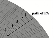
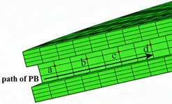
To accurately quantify this non-uniformity, two critical analysis paths are defined on the disc body in the research, namely the end-face radial path PA and the rib-side radial path PB, as illustrated in Fig. 7. Path PA is arranged along the radial direction of the frictional working end face of the brake disc, extending from the edge of the hub mounting flange to the outer edge of the brake disc and penetrating the core zone of frictional heat generation and the transition zone of heat diffusion, and it is employed to extract the temperature and equivalent stress at positions with different radii. Path PB is arranged along the radial direction of the side faces of the brake disc ribs, covering the main heat dissipation channels inside the disc body. It is adopted to reveal the temperature and stress responses of the rib structure in the process of heat conduction and evaluate the influence of the internal heat dissipation structure on the overall thermal uniformity.
Fig. 7Setting of paths in different directions
a) Path of PA
b) Path of PB
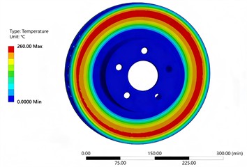
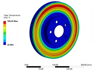
The transient temperature fields of the brake disc at different time instants are shown in Fig. 8. It can be observed that at the moment when the braking pressure loading is completed (1 s), the temperature of the annular friction band in contact between the brake disc and the brake pad is significantly elevated, with the maximum temperature reaching 260 ℃, and a high-temperature ring zone centered on the outer friction edge is formed. The temperature is decreased gradually from the outside to the inside, and the lowest temperature is monitored in the regions of the central mounting hole and bolt holes. The isotherms exhibit a clear concentric ring pattern, which manifests the instantaneous state that frictional heat generation is merely concentrated in the contact area and has not been fully conducted towards the internal structure of the disc. After unloading, at the moment of 1.5 s, no external frictional heat is imported into the brake disc. Under the combined actions of heat conduction, convective heat transfer and radiative heat dissipation, the overall temperature level of the brake disc is significantly attenuated, and the maximum temperature is reduced to 184.25 ℃. Meanwhile, the high-temperature ring zone is slightly diffused towards the inner side, and the temperature of the central low-temperature region is slightly raised. The isotherms still retain a ring-shaped distribution but with a gentler gradient, which reflects the process that heat is homogenized inside the disc and dissipated to the ambient environment.
Fig. 8Distribution of brake disc temperature fields at different time instants
a) 1 s
b) 1.5 s
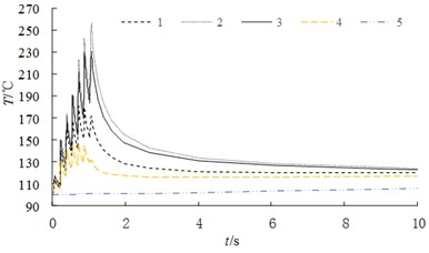
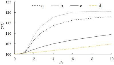
The variations in node temperatures along different paths of the brake disc are presented in Fig. 9. It can be observed that the temperature of Path PA adjacent to the outer friction edge rises rapidly with intense high-frequency fluctuations during the braking loading phase of 0-1 s. Furthermore, the nodes closer to the outer edge are featured by stronger fluctuations and higher peak temperatures. Such serrated oscillations are directly recognized as the thermal signatures of unstable vibrations at the braking interface, such as stick-slip vibration and normal vibration. After unloading (1-10 s), the temperature is reduced rapidly and tends to be stabilized, and the fluctuations are completely eliminated. The temperature of inner Path PB distant from the friction interface shows a smooth and monotonic increment without any fluctuations, and the temperature is increased slowly merely through heat conduction. It is demonstrated that vibrations are concentrated in the friction contact region and attenuate rapidly towards the inner side in the radial direction, whereas the non-contact region is not involved in the thermo-vibrational coupling.
Fig. 9Variation law of node temperature along different paths
a) Path of PA
b) Path of PB
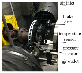
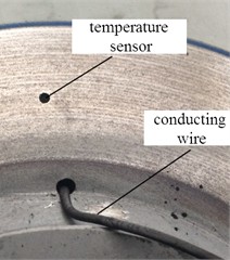
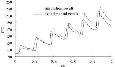
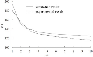
To verify the accuracy of the thermo-mechanical coupled model of the brake disc, temperature data in the friction region of the brake disc is collected in real time by mounting temperature sensors, pressure sensors and ventilation ducts on the brake assembly, as shown in Fig. 10. The experimental and simulation results are compared, as displayed in Fig. 11. The results indicate that during the braking loading phase of 0-1 s, both the simulation and experimental curves are characterized by a stepwise temperature rise accompanied by high-frequency fluctuations, and the peak values and fluctuation tendencies are highly consistent. During the unloading and heat dissipation phase of 1-10 s, a monotonic temperature attenuation followed by gradual stabilization is observed for both sets of data, and the variation rate is basically consistent with the final steady-state temperature level. Overall, the simulation results are in good agreement with the experimental data in terms of the temperature evolution law, peak magnitude and fluctuation characteristics, which confirms that the established thermo-mechanical coupled model can accurately describe the dynamic variation of the temperature field during the braking process.
Fig. 10Experimental validation scheme for the thermo-mechanical coupled model
a) Mounting of the brake assembly
b) Mounting of temperature sensor
Fig. 11Validation of node temperature values
a) 0-1 s
b) 1-10 s
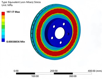
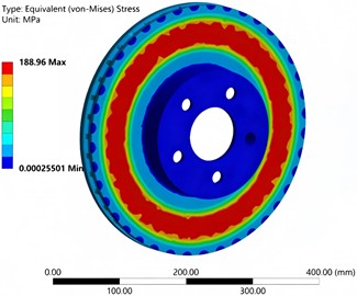
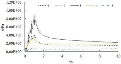
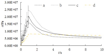
The equivalent stress field distributions of the brake disc at different time instants are presented in Fig. 12, which generally exhibits a concentric annular characteristic featuring high stress in the outer friction band and low stress in the central mounting zone. At the end of braking loading, the maximum equivalent stress reaches 197.17 MPa, and the high-stress region is concentrated on the annular friction surface in contact with the brake pad, with distinct and well-graded isostress contours. At 0.5 s after unloading, the maximum equivalent stress is reduced to 188.96 MPa, the high-stress annular band is slightly diffused inward, and the overall stress level is attenuated slightly, which reflects the process of stress relaxation and thermal stress redistribution after the unloading of braking load. The variation laws of node stress along different paths are illustrated in Fig. 13.
Fig. 12Distribution of brake disc stress fields at different time instants
a) 1 s
b) 1.5 s
Fig. 13Variation law of node stress along different paths
a) Path of PA
b) Path of PB
It can be observed that the stress of Path PA adjacent to the outer friction edge rises rapidly with high-frequency fluctuations during the 0-1 s loading phase; the nodes closer to the outer edge present higher stress peaks and more intense fluctuations, and the stress is rapidly attenuated and tends to be stable after unloading. Path PB, which is far away from the friction interface, features a lower stress peak, gentler fluctuations and a slower stress attenuation rate after loading, indicating that the braking stress is concentrated in the friction contact region and attenuates significantly with the increase in radial distance. Meanwhile, the high-frequency fluctuations of the stress curve are highly synchronized with the oscillation characteristics of the temperature curve, which further verifies the strong correlation between thermo-mechanical coupling and vibration during the braking process.
2.5. Modal analysis
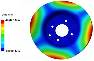
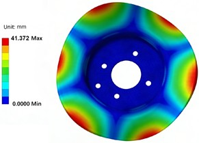
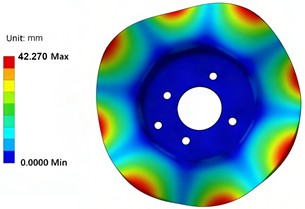
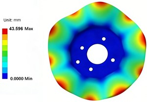
The first four mode shapes of the brake disc are presented in Fig. 14. All mode shapes are characterized by extremely small displacement in the central mounting region and remarkable displacement in the outer friction region. The first-order mode manifests a two-lobed elliptical bidirectional bending deformation; the second-order mode exhibits a four-lobed quincuncial in-plane bending-torsion coupled deformation; the third-order mode corresponds to a five-lobed irregular polygonal local bending deformation; and the fourth-order mode presents a six-lobed symmetric polygonal deformation. With the elevation of the modal order, the number of lobes in the circumferential direction is increased gradually, and the vibration morphology evolves from global bending to local refined deformation. This phenomenon is highly consistent with the boundary conditions of the brake disc, in which the outer edge is free and the center is constrained, and also reveals the mechanical mechanism underlying the tendency of brake vibration and noise to concentrate in the outer friction region.
Fig. 14The first four modal shapes
a) The first order
b) The second order
c) The third order
d) The fourth order
To verify the accuracy of the dynamic characteristics of the finite element model for the brake disc, modal testing is conducted by adopting the hammer impact method, and the experimental scheme is shown in Fig. 15. Transient excitation is exerted on the brake disc through an impact hammer, and vibration response signals are acquired by acceleration sensors. After being processed by the data acquisition system and modal analysis software, the first six orders of natural frequencies are identified and verified through comparison with the simulation calculation results. Table 3 lists the test and simulation results of the first six natural frequencies of the brake disc. It can be observed from the table that the experimental values are in good agreement with the simulation values for each order of natural frequency, and all the relative errors are controlled within 4.5 %. In addition, the relative error shows an overall downward trend with the increase of modal order, and the relative error of the sixth order is merely 1.6 %. The small relative errors demonstrate that the established calculation model for the natural frequencies of the brake disc possesses high accuracy and reliability.
Fig. 15Test scheme for natural frequencies
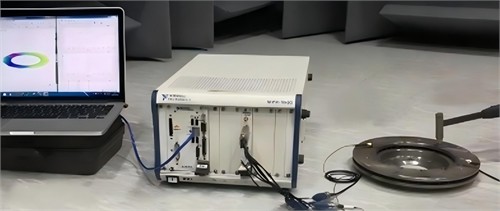
Table 3Test and calculation results of natural frequencies
Order | 1 | 2 | 3 | 4 | 5 | 6 |
Test value of natural frequency / Hz | 1074 | 1571 | 1913 | 2284 | 2859 | 2963 |
Simulation value of natural frequency / Hz | 1026 | 1509 | 1832 | 2215 | 2781 | 2915 |
Relative error / % | 4.5 | 3.9 | 4.2 | 3.0 | 2.7 | 1.6 |
According to the modal analysis results, the first-order natural frequency of the brake disc ranges from 1000 to 1100 Hz. In accordance with T/CAAMTB 90-2022 Test Method and Evaluation Index for Natural Frequency of Automotive Brake Discs, this natural frequency does not fall within the optimal range of 1400-1800 Hz. When the first-order natural frequency is within this range, it can effectively avoid the brake judder excitation band of 0-80 Hz and the sensitive coupling frequency band of brake squeal at 3-12 kHz, ensuring sufficient modal separation from system components such as calipers and brake pads, and significantly improving the brake NVH performance. Meanwhile, this range can notably enhance the out-of-plane stiffness of the brake disc and the structural safety margin, taking into account the frequency attenuation margin of gray cast iron under high-temperature conditions to ensure thermal modal stability, without causing issues such as increased unsprung mass and deteriorated heat dissipation performance due to excessive structural reinforcement. It is the optimal balance range that comprehensively considers brake NVH, structural stiffness, thermo-mechanical performance, and vehicle chassis matching. Therefore, this natural frequency range can be set as the optimization target for vibration reduction.
3. Structural optimization based on multi-objective method
3.1. Design of optimization plan
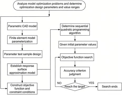
To improve the vibration suppression performance of the brake disc, an optimization strategy combining parametric modeling and response surface surrogate model is proposed, as shown in Fig. 16. The strategy is formulated on the premise that the peak stress and peak temperature are not increased, aiming to search for the structural parameters that satisfy the range of 1400-1800 Hz for the first-order natural frequency, with the minimum mass set as the optimization objective. Firstly, the model optimization problem is analyzed, and the optimal design parameters as well as their value ranges are determined. A parametric CAD model of the brake is established, and the parametric modification of the finite element model is completed, thereby realizing the driven update of the geometric and simulation models by the design variables. Subsequently, the design of experiments (DOE) is carried out based on the design parameters, and a response surface approximation model is constructed to replace the time-consuming finite element simulation [18-21]. The mathematical optimization model is established in combination with the constraint conditions and the objective function. On this basis, the Sequential Quadratic Programming (SQP) algorithm is selected as the core optimization algorithm, and the search for the objective function is performed after the initial parameter values are assigned. The precision criterion verification is implemented for the results of each search iteration. If the convergence target is not satisfied, the parameters are updated and the iteration is restarted until the optimization objective is achieved and the search is terminated. Finally, the optimal combination of structural parameters satisfying the constraint conditions is obtained. By integrating the surrogate model with the high-efficiency mathematical programming algorithm, the proposed method enables the efficient synergistic improvement of the lightweight design and dynamic performance of the brake on the premise that the mechanical and thermal performance constraints are guaranteed.
Fig. 16The optimization process of structural parameters for the brake disc
3.2. Establishment of response surface model and error calibration
The coupling effects of key geometric parameters of the ventilated brake disc on its thermo-mechanical properties, natural modal characteristics and mass index are comprehensively considered, and the total thickness , ventilation groove height , fin inclination angle and number of fins of the brake disc are selected as the core design variables for the present optimization design. The structural positions and geometric definitions of each variable are illustrated in Fig. 17. Meanwhile, the reasonable value ranges of the above design variables are determined in combination with vehicle assembly constraints, casting manufacturability and mechanical performance boundary conditions, and the specific ranges are specified in Table 4. Given that the ventilation structure of the brake disc is characterized by central rotational symmetry, the symmetrical distribution law of its structural parameters is proven to exert a significant influence on thermal field uniformity, vibration response characteristics and performance stability.
Table 4Range of design variable
Design variable | / mm | / mm | / ° | N |
Initial value | 25 | 10 | 3 | 26 |
Lower limit value/Upper limit value | 20/30 | 7/13 | 2/4 | 22/30 |
To more comprehensively and accurately reflect the action mechanism of the variation in symmetrical structural parameters on the comprehensive performance of the brake disc, the classical Central Composite Design (CCD) in the field of experimental design is adopted in this study to implement discrete data sampling. As an efficient sampling approach for response surface optimization, multidimensional key information including the correlation of sample variables and the distribution law of sample errors can be obtained with the minimum number of experimental iteration cycles and simulation computational cost. Moreover, the influence laws of structural variation on the brake disc performance under the action of single parameters and parameter interactions can be more remarkably revealed compared with conventional sampling methods. Through the design of sample data, the response relationship curves of mass and first-order natural frequency can be calculated as shown in Fig. 18 and Fig. 19, respectively. It can be seen that each response value does not have the characteristics of linearity and monotonicity.
Fig. 17Definition of design variables
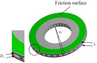
Fig. 18The response of structural parameters to mass
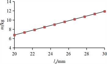
a) Response of to
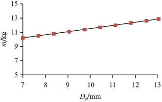
b) Response of to
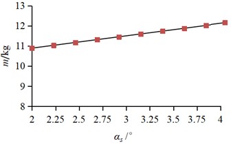
c) Response of to
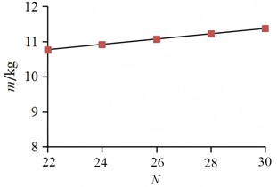
d) Response of to
As a classical approximate modeling technique in structural optimization design, the Response Surface Methodology (RSM) establishes its corresponding mathematical model termed as the fitting function. Relying on the discrete sampling data acquired from the Design of Experiments (DOE), this modeling approach can efficiently construct the mapping relationship between design variables and optimization objectives, thereby accomplishing the fitting construction of the objective function. In the multi-parameter optimization of the brake disc, the output response of the objective function and the design parameters do not follow a simple continuous linear mapping law, but present complicated nonlinear coupling characteristics. Consequently, the first-order linear response model fails to accurately characterize the real response properties of the system. In view of the engineering characteristics that the interval of the optimal scale search space is relatively narrow and the sensitivity of the response surface output to the variation of independent variables is low in this brake disc optimization, the second-order response surface formulation is ultimately adopted in this paper as the fitting function to precisely characterize the response law of the objective function, with a comprehensive trade-off between the model fitting accuracy and numerical computational efficiency.
Fig. 19The response of structural parameters to the first natural frequency
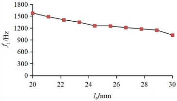
a) Response of to
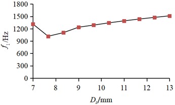
b) Response of to
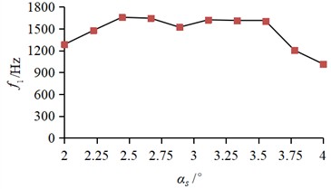
c) Response of to
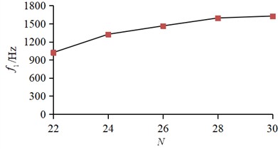
d) Response of to
Define as , as , as and as , the fitting objective function can be expressed as:
where , , are undetermined regression coefficient.
According to the least square method, the regression analysis of error ε can be obtained:
where is actual discrete response value, is the number of samples.
The formula of regression coefficient is:
By approximate fitting, the response surface function can be obtained:
where is the mass fitting function, is the first natural frequency fitting function.
In the research involving numerical analysis and optimal design based on the response surface model, fitting deviations inevitably exist between this model and the actual response model, and the magnitude of such deviations directly determines the reliability and accuracy of the overall optimal design results. To effectively ensure the prediction accuracy of the constructed fitting function and prevent excessive fitting errors from exerting adverse impacts on the conclusions of subsequent analyses, strict accuracy verification of the fitting performance is indispensable. When the error value derived from the verification lies within the reasonable range permitted by engineering applications, it can be verified that the fitting function features outstanding reliability and practical feasibility. In this paper, the fitting accuracy of response surface function is evaluated by fitting decision coefficient , correcting decision coefficient and root mean square error RMS. The computational formula is shown as follows:
where is actual response value of optimization objective, is average response value, is term number of fitting function.
Employing the identical response surface construction methodology, the fitting functions for peak stress and peak temperature can be derived as:
where is the peak temperature fitting function, is the peak stress fitting function.
The fitting decision coefficient , correcting decision coefficient and root mean square error RMS of optimization objectives can be calculated as in Table 5. It can be seen that the response surface functions of mass, first-order natural frequency, temperature peak, and stress peak all have good fitting accuracy, with a maximum deviation of less than 3.5 %, which can effectively ensure the reliability of the optimization results.
Table 5Evaluation parameter of error
Error checking parameter/ Optimization objective | (the ideal value is 1) | (the ideal value is 1) | RMS (the ideal value is 0) |
0.99598 | 0.99111 | 0.00802 | |
0.97894 | 0.95383 | 0.04168 | |
0.90454 | 0.91337 | 0.17410 | |
0.91409 | 0.92247 | 0.20181 |
Since the data for multi-objective optimization is obtained from finite element analysis (FEA), it is essential to verify the deviation between the fitting function and the simulation results. The corresponding verification results are listed in Tables 6-8. It can be concluded that the fitting scheme employing the response surface function exhibits high reliability and satisfactory model accuracy.
Table 6Results of comparison between fitting function and FEA model for f1
Number | Calculation type | / mm | / ° | / mm | / Hz | Calculation error of fitting function / % | |
1 | fitting function | 23.48 | 2.23 | 8.25 | 26 | 1473 | 1.3 |
FEA model | 1454 | ||||||
2 | fitting function | 22.55 | 3.00 | 8.80 | 30 | 1492 | 1.6 |
FEA model | 1468 |
Table 7Results of comparison between fitting function and FEA model for Tmax
Number | Calculation type | / mm | / ° | / mm | / ℃ | Calculation error of fitting function / % | |
1 | fitting function | 24.02 | 2.29 | 8.26 | 30 | 264.013 | 0.8 |
FEA model | 266.36 | ||||||
2 | fitting function | 24.56 | 2.08 | 8.16 | 26 | 267.983 | 2.1 |
FEA model | 262.20 |
Table 8Results of comparison between fitting function and FEA model for σmax
Number | Calculation type | / mm | / ° | / mm | / MPa | Calculation error of fitting function / % | |
1 | fitting function | 22.87 | 3.47 | 8.38 | 30 | 202.34 | 1.7 |
FEA model | 198.86 | ||||||
2 | fitting function | 22.76 | 2.16 | 8.05 | 30 | 196.65 | 3.5 |
FEA model | 190.07 |
3.3. Solution of optimization mathematical model
Based on the integrated simulation environment of ANSYS Workbench, a multidisciplinary constrained optimization workflow is constructed via the Design Explorer optimization module, and a complete optimization mathematical model is established as shown in Eq. (20) and Eq. (21). Multiple constraint criteria are specified in this optimization design: the peak temperature and peak stress of the structure shall not exceed the initial design baseline, and the first-order natural frequency must meet the design interval requirement of 1400 Hz 1800 Hz; the optimization objective function is set as the minimization of the structural mass. To ensure the optimization search efficiency and solution stability under nonlinear constraints, the Sequential Quadratic Programming (SQP) algorithm is selected as the core solution algorithm. Leveraging the quadratic approximation property of the algorithm for the objective function and constraint conditions, a global optimization search is performed in the design space, and the optimal design scheme with the minimum mass that satisfies all constraints is finally obtained:
where is the design variable matrix, is the response function of mass, is the response function of the first natural frequency, is the response function of peak temperature, is the stress peak response function, is lower limit of design variables; is upper limit of design variables (search results of x4 need to be integers).
Through continuous iterative computation, ANSYS provides three recommended optimization results, as listed in Table 9. It can be observed that under the strict constraints that the peak temperature and peak stress do not increase, this multi-objective optimization successfully reduces the structural mass by 1.74 %-3.59 %, while increasing the first-order natural frequency by 4 %-9 % and stabilizing it within the range of 1400-1800 Hz. The collaborative optimization of lightweight design and dynamic performance is realized, providing feasible schemes and theoretical basis for the efficient design of such structures.
The applicability of the three optimization schemes can be evaluated from three aspects: processability, cost and comprehensive NVH performance. In terms of processability, Scheme B has the largest fin inclination angle and compact structural layout, which results in smaller casting errors. In terms of manufacturing cost, Scheme A features the lightest structural mass, so its overall cost is relatively low. With regard to NVH performance, Scheme B achieves the highest natural frequency and therefore possesses the optimal anti-vibration performance.
Table 9Multi-objective optimization results
Parameter | / mm | / ° | / mm | / kg | / Hz | / ℃ | / MPa | |
Result A | 27.86 | 8.44 | 2.28 | 30 | 8.87 | 1456 | 260.0 | 197.0 |
Result B | 26.10 | 8.12 | 2.34 | 30 | 9.04 | 1526 | 260.0 | 197.0 |
Result C | 24.56 | 8.16 | 2.08 | 30 | 8.89 | 1488 | 259.9 | 197.0 |
4. Conclusions
1) The established thermal-structural-modal coupling analysis model of the braking system took the influence of thermal stress on the natural frequency of the brake disc into account, and the problem that the results of traditional modal calculation had a relatively large deviation from the actual boundary conditions was successfully solved. Verified by tests, the maximum error between the simulated temperature field of the brake disc and the test data was 3.5 %, the relative errors between the simulated values and test values of the first to sixth order natural frequencies were all controlled within 4.5 %, and the deviation between the simulated peak value of the stress field and the test value was less than 5 %. This model could accurately describe the coupling mechanism of thermal, structural and modal fields during the braking process, and a high-precision simulation basis was provided for subsequent optimization.
2) Experimental design was completed based on Central Composite Design (CCD). The surrogate model constructed by the quadratic response surface method had excellent fitting accuracy. This model could effectively characterize the nonlinear coupling relationship between design variables and multiple performance indicators of the brake disc, and a reliable mathematical basis was provided for efficient multi-objective optimization.
3) With the minimum mass of the brake disc as the objective, multi-objective collaborative optimization was completed by combining the Sequential Quadratic Programming (SQP) algorithm. On the premise of strictly restricting the peak temperature ≤ 260 ℃ and peak stress ≤ 197 MPa (not exceeding the initial design benchmark), the first-order natural frequency was successfully optimized to the optimal range of 1400-1800 Hz. After optimization, the mass of the brake disc was reduced by 1.74 %-3.59 % compared with the initial design, and the first-order natural frequency was increased by 4 %-9 %, realizing the dual improvement of lightweight and vibration damping performance. The brake disc is manufactured by casting, so only minor local modifications are adopted in the structural optimization. Its optimized fin inclination ranges from 2.08° to 2.34°, lower than the original value of 3°, which reduces demoulding difficulty and enhances casting accuracy to some extent. Since the original production processes, moulds and machining procedures are retained, the structural adjustments will not raise processing costs. In contrast, the weight reduction effectively lowers material costs. Furthermore, following the selection principles for design variables, the external assembly dimensions and spatial layout relative to adjacent parts stay the same. The brake disc causes no assembly interference with other chassis components and fully satisfies practical engineering demands.
4) The current structural optimization study of brake discs is mainly carried out under emergency braking conditions. This working condition setting is suitable for basic theoretical research and can effectively support the exploration and verification of the multi-field coupling optimization method for brake discs, which demonstrates sufficient rationality and scientificity of the research setup. To make the research outcomes adaptable to more practical braking scenarios, we will further improve the research system in future work. Various complex and variable braking boundary conditions, including different braking speeds, braking pressures, friction coefficients, heat dissipation environments, and repeated braking processes, will be comprehensively considered to conduct performance analysis and optimization iteration under multi-parameter coupling, thereby further expanding the applicable scope of the proposed optimization technical scheme.
References
-
J. Huang and J. Liu, “Strength constrained topology optimization of hyperealstic structures with large deformation-induced frictionless contact,” Applied Mathematical Modelling, Vol. 126, No. 2, pp. 67–84, Oct. 2023, https://doi.org/10.1016/j.apm.2023.10.032
-
D. Zhu et al., “Noise and vibration performance of automotive disk brakes with laser-machined M-shaped grooves,” Proceedings of the Institution of Mechanical Engineers, Part D: Journal of Automobile Engineering, Vol. 237, No. 5, pp. 978–990, May 2022, https://doi.org/10.1177/09544070221085972
-
H. Li, G. Wang, B. Wei, H. Liu, and W. Huang, “Improved variational mode decomposition method for vibration signal processing of flood discharge structure,” Journal of Vibration and Control, Vol. 28, No. 19-20, pp. 2556–2569, May 2021, https://doi.org/10.1177/10775463211016132
-
S. Gaygol and K. Wani, “Modal analysis of plate to analyze the effect of mass stiffeners using the Chladni plate approach,” Materials Today: Proceedings, Vol. 72, No. 3, pp. 1314–1321, Sep. 2022, https://doi.org/10.1016/j.matpr.2022.09.305
-
X. Li, D. Zhao, H. Zhai, M. Chen, and T. Zhang, “Modal analysis of circular arches in rectangular coordinate system,” Structures, Vol. 47, No. 1, pp. 2129–2137, Dec. 2022, https://doi.org/10.1016/j.istruc.2022.12.036
-
R. F. Zhou, M. X. Feng, M. Z. Jiang, and K. X. Dong, “Research on fatigue damage of sucker rod based on damage mechanics,” Applied Mechanics and Materials, Vol. 633-634, pp. 1117–1123, Aug. 2014, https://doi.org/10.4028/www.scientific.net/amm.633-634.1117
-
F. Noohi, A. Nikoobin, and M. R. Ashory, “Developing an accurate finite element model for brake disc in contact with the pad using experimental modal analysis,” Proceedings of the Institution of Mechanical Engineers, Part D: Journal of Automobile Engineering, Vol. 239, No. 13, pp. 6522–6533, Nov. 2024, https://doi.org/10.1177/09544070241295411
-
N. Gräbner, D. Schmid, and U. Von Wagner, “On drum brake squeal-assessment of damping measures by time series data analysis of dynamometer tests and complex eigenvalue analyses,” Machines, Vol. 11, No. 12, p. 1048, Nov. 2023, https://doi.org/10.3390/machines11121048
-
V. K. Agrawal et al., “Optimizing ventilated disk brake design for enhanced thermal performance: an analytical and experimental approach,” Multiscale and Multidisciplinary Modeling, Experiments and Design, Vol. 8, No. 4, pp. 213–213, Mar. 2025, https://doi.org/10.1007/s41939-025-00797-0
-
H. Lee and H.-S. Yoon, “Acoustic radiation from modal vibration of automotive brake drum,” Journal of Mechanical Science and Technology, Vol. 31, No. 7, pp. 3211–3218, Aug. 2017, https://doi.org/10.1007/s12206-017-0610-6
-
R. N. Ferreira, J. C. Falleiros, P. R. Zampieri, J. V. Ferreira, and M. L. Bittencourt, “Experimental and numerical fatigue evaluation of lightweight crankshafts,” Results in Engineering, Vol. 23, p. 102730, Aug. 2024, https://doi.org/10.1016/j.rineng.2024.102730
-
S. M. Radu, F. D. Popescu, A. Andraș, Z. Virág, I. Brînaș, and M.-I. Draica, “A thermo-mechanical stress based fatigue life evaluation of a mine hoist drum brake system using COMSOL Multiphysics,” Materials, Vol. 15, No. 19, p. 6558, Sep. 2022, https://doi.org/10.3390/ma15196558
-
O. Jassinbekov, M. Isametova, and G. Kaldan, “Development of a technique for computer simulation of the stress state of the drive drum shell of a belt conveyor to optimize its design parameters,” Eastern-European Journal of Enterprise Technologies, Vol. 2, No. 7 (110), pp. 31–39, Apr. 2021, https://doi.org/10.15587/1729-4061.2021.229213
-
H. K. Celik, I. Akinci, N. Caglayan, and A. E. W. Rennie, “Structural strength analysis of a rotary drum mower in transportation position,” Applied Sciences, Vol. 13, No. 20, p. 11338, Oct. 2023, https://doi.org/10.3390/app132011338
-
L. Quynh, Z. Jianrun, N. Liem, B. Cuong, L. X. Long, and D. T. Phuong, “Experimental modal analysis and optimal design of cab’s isolation system for a single drum vibratory roller,” Vibroengineering Procedia, Vol. 31, pp. 52–56, May 2020, https://doi.org/10.21595/vp.2020.21325
-
J. Wang, C. Xu, Y. Xu, X. Qi, Z. Liu, and H. Tang, “Vibration analysis and parameter optimization of the longitudinal axial flow threshing cylinder,” Symmetry, Vol. 13, No. 4, p. 571, Mar. 2021, https://doi.org/10.3390/sym13040571
-
S. de Carolis, A. Messina, and L. Soria, “Modal analysis through response-based FRFs: additional modes for local diagnoses,” Journal of Sound and Vibration, Vol. 549, No. 1, p. 117574, Jan. 2023, https://doi.org/10.1016/j.jsv.2023.117574
-
R. Talebitooti, M. Zarastvand, and H. Darvishgohari, “Multi-objective optimization approach on diffuse sound transmission through poroelastic composite sandwich structure,” Journal of Sandwich Structures and Materials, Vol. 23, No. 4, pp. 1221–1252, 2019, https://doi.org/10.1177/1099636219854748
-
R. Talebitooti, H. D. Gohari, and M. R. Zarastvand, “Multi objective optimization of sound transmission across laminated composite cylindrical shell lined with porous core investigating Non-dominated Sorting Genetic Algorithm,” Aerospace Science and Technology, Vol. 69, No. 1, pp. 269–280, Jun. 2017, https://doi.org/10.1016/j.ast.2017.06.008
-
H. D. Chalak, A. M. Zenkour, and A. Garg, “Free vibration and modal stress analysis of FG-CNTRC beams under hygrothermal conditions using zigzag theory,” Mechanics Based Design of Structures and Machines, Vol. 51, No. 8, pp. 4709–4730, Aug. 2023, https://doi.org/10.1080/15397734.2021.1977659
-
A. Daşdemir, “A modal analysis of forced vibration of a piezoelectric plate with initial stress by the finite-element simulation,” Mechanics of Composite Materials, Vol. 58, No. 1, pp. 69–80, Mar. 2022, https://doi.org/10.1007/s11029-022-10012-7
About this article

The paper is supported by provincial scientific research projects (62874155).
The datasets generated during and/or analyzed during the current study are available from the corresponding author on reasonable request.
The authors declare that they have no conflict of interest.