Abstract
To investigate the transient flow characteristics and flow field hysteresis mechanism within a centrifugal pump during variable speed regulation, this paper selects a double-volute, semi-open impeller centrifugal pump as the research object, through the Pro/E software modeling for centrifugal pump 3-d full port, choosing Renault N-S equation and standard - turbulence model, using CFX software perform numerical simulations process of centrifugal pump up or slow down the transient flow characteristics to carry on the numerical simulation, the evolution law of flow field in centrifugal pump during variable speed adjustment is studied and analyzed. The results demonstrate that the internal pressure, flow velocity, turbulent kinetic energy, and vorticity within the centrifugal pump exhibit distinct transient characteristics during variable speed regulation. During the acceleration phase, as the rotational speed elevates, the internal pressure of the pump increases along with an expanded pressure fluctuation range, the vorticity within the impeller passage increases, the vorticity in the volute chamber decreases, and the fluid velocity and turbulent kinetic energy change obviously in the middle region of the blade working face and the blade tip region. In the process of deceleration, with the decrease of rotational speed, the pressure in the centrifugal pump decreases, the vorticity in the impeller passage decreases, and the vorticity in the volute increases first and then weakens. When 0.4 s, pressure on the outlet wall of the volute of the centrifugal pump increases obviously, and the flow velocity and turbulent kinetic energy likewise change obviously in the middle region of the blade working face and the blade tip region. Quantitative comparison further reveals an obvious transient hysteresis effect: under identical rotational speed, the overall pressure and turbulent kinetic energy in deceleration process are higher than those in acceleration process, which provides a new physical understanding of flow discrepancy between two variable-speed modes lacking in previous qualitative researches.
1. Introduction
Centrifugal pumps, as one of the key equipment in water transportation systems, are widely used in various fields such as water supply and drainage [1-4]. With the continuous development of science and technology, the operational stability of centrifugal pumps has garnered extensive attention [5-8]. Generally, the operating conditions of centrifugal pumps are relatively stable. However, with the continuous development of technology, merely operating under stable conditions can no longer meet the demands [9-12]. Therefore, the research on the transient process of centrifugal pumps under variable operating conditions has become particularly important. Compared with some transient operations of centrifugal pumps (such as rapid startup, power-off shutdown, and valve adjustment, etc.), research in this area has developed relatively slowly. Ma et al. [13] investigated the transient flow features inside the centrifugal pump during its startup phase by simulating the full speed variation process of the unit, and found that during the initial stage of the pump startup, both the transient head and the transient efficiency exhibited pulsation phenomena. Liang et al. [14] explored the transient external features of a centrifugal pump throughout startup and shutdown, and found that during variable-frequency startup, the time required for inlet and outlet pressure stabilization rose notably as the relative flow rate approached the rated value, which did not occur during power-frequency startup. Ye et al. [15] proposed a modified partially averaged Navier-Stokes model (MSST PANS) and used it to study the unstable turbulence in a centrifugal pump considering the curvature and rotation effects, assessing the reliability of the MSST PANS model and analyzing the flow instability in the centrifugal pump. They concluded that the high-velocity gradient flow at the inlet of the blade passage and the backflow phenomenon at the impeller outlet were the primary causes of the high turbulent kinetic energy in the impeller. Yang et al. [16] explored the influence mechanism of flow separation and vortex phenomena observed in the blade diffuser of a centrifugal pump under near-stall operating conditions, and found that when the pump unit operated under near-stall conditions, the dominant frequency was primarily governed by the large-scale vortex structures in the volute diffuser. Chen et al. [17] conducted shell vibration and shaft vibration tests on the centrifugal pump unit under different operating conditions. The vibration intensity of the shell vibration showed fluctuations with the increase of flow rate, while it generally increased with the increase of rotational speed. Wang et al. [18] investigated the pressure pulsation characteristics in the flow passage and the transient stress characteristics of the impeller during the shutdown phase of the centrifugal pump unit. They simulated the transient shutdown process of the centrifugal pump unit and analyzed the structural stress and deformation behavior of the impeller using a one-way fluid-structure coupling method. Zhao et al. [19] analyzed the pressure pulsation characteristics under different startup speeds by combining numerical simulation with experimental verification. These findings can provide important theoretical guidance for the design and safe operation of large-scale water pumping systems. Gangipamula Rajavamsi et al. [20] used DES to simulate the transient process of low specific speed pumps and studied the hydrodynamic characteristics of narrow channel centrifugal pumps. During the transient operation of centrifugal pumps under variable working conditions, if the operation is improper, it will lead to energy waste, reduced pump service life, and even possible major accidents, posing safety hazards.
From the above, it can be seen that although there are some achievements in the transient research of centrifugal pumps, most of the research results are focused on the startup and shutdown processes of centrifugal pumps, and there are relatively few studies on the variable speed regulation of centrifugal pumps, and most of them are limited to the pressure pulsation characteristics of centrifugal pumps. Existing studies rarely conduct synchronous comparative analysis of multi-physical fields including velocity, vorticity and turbulent kinetic energy; furthermore, the differential flow evolution mechanism and hysteresis phenomenon between acceleration and deceleration under the same rotational speed have not been quantitatively revealed, which fails to support refined control of variable-speed pumps. The flow field evolution law inside the centrifugal pump during variable speed regulation remains relatively complex. During the regulation process, improper regulation may affect the operational stability of the centrifugal pump and even seriously threaten the security of the centrifugal pump system, which has significant research significance. Therefore, based on the research achievements of predecessors, this paper selects the Reynolds-averaged N-S equation and the standard - turbulence model, and uses ANSYS CFX software to perform meshing on the centrifugal pump. Unsteady numerical simulation calculations are conducted for the acceleration and deceleration processes of the centrifugal pump. The pressure field and velocity field cloud diagrams and variation curves inside the pump are obtained. The turbulent kinetic energy and vorticity cloud diagrams at the impeller and the streamlines at the volute are drawn to obtain the research results of the internal flow features of the centrifugal pump during the transient phase of centrifugal pump under variable operating conditions, providing a reference for the variable speed regulation operation of the centrifugal pump. Different from previous single-index qualitative analysis, this study quantitatively compares flow parameters at multiple monitoring points, clarifies opposite vortex evolution rules of impeller and volute in two speed-changing processes, and supplements novel mechanistic insights for variable-speed transient flow research.
2. Research object and numerical method
2.1. Centrifugal pump geometry model
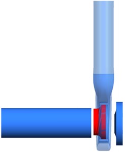
This paper adopts a single-stage, single-suction semi-open impeller centrifugal pump as the research object, with a rated flow rate 380 m3/h, a rated head 76 m, and a rated speed 2950r/min, number of impeller blades 6, efficiency 82.8 %, specific speed 136, impeller inlet diameter 200 mm, impeller outer diameter 259 mm Hub diameter 75 mm. A three-dimensional full-flow passage model of the centrifugal pump was established using Pro/E. Shown in Fig. 1.
Fig. 1Three-dimensional geometry model of the centrifugal pump
2.2. Mesh generation and verification of mesh independence
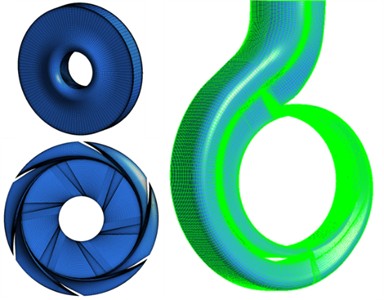
Mesh generation for the centrifugal pump's three-dimensional geometry was performed using ICEM CFD 18.0. To ensure the accuracy of the calculation, structured meshing was carried out for the entire flow passage of the centrifugal pump. The established mesh model of the centrifugal pump is shown in Fig. 2.
Fig. 2Meshing of the three-dimensional model of the centrifugal pump
Grid independence verification for the full flow passage of the centrifugal pump at rated operating conditions. As shown in Table 1, when the number of grids is 2.53 million, the relative error of head is 2.21 % and that of efficiency is 1.00 %; when the number of grids is 3.08 million, the relative error of head is 1.97 % and that of efficiency is 0.39 %; when the number of grids is 3.63 million, the relative error of head is 1.95 % and that of efficiency is 1.55 %. By comparing the discrepancies in head and efficiency across different grid resolutions, when the grid number reached 3.08 million, the accuracy of head and efficiency calculation improved little and even showed a downward trend. Therefore, considering the computing resources and time costs comprehensively, 3.08 million calculation units were selected for calculation.
Table 1Verification of grid independence
Number of grid nodes | Head /m | Efficiency / % |
2530690 | 77.68 | 83.63 |
3080630 | 77.50 | 83.12 |
3632720 | 77.48 | 84.08 |
2.3. Numerical calculation method
A pressure inlet boundary condition is applied at the pump inlet, while a mass flow rate boundary condition is specified at the outlet. To ensure reliable results, the centrifugal pump runs at a constant speed for 0.1 s before the rotational speed transient. The calculation step is set to 0.000225989 s. To guarantee absolute convergence at each time step, the maximum inner iterations are set to 50, and the convergence accuracy is set to 1×10⁻⁵. Select the standard - turbulence model that can simulate complex flows well. Supplementary explanation for model selection: The studied pump operates within 0.6-1.0 without severe stall and large-scale flow separation, and the curvature effect of the semi-open impeller is moderate. The standard - model owns good computational stability and low computing cost for long-time unsteady transient simulation, and has been widely adopted in similar centrifugal pump steady and variable-speed simulations in published literatures. Admittedly, this model has limitations in predicting strong rotational curvature and separation vortex compared with SST k−ω or DES; follow-up sensitivity analysis on advanced turbulence models will be carried out in further research. Set the speed variation time to 0.3 [8-9] seconds and the speed variation mode to linear. To ensure the accuracy of the calculation, when 0.1 s, the centrifugal pump operates stably at the target speed, and when 0.1 s, the speed of the centrifugal pump begins to change, as expressed by Eqs. (1-2).
Formula for variation in the speed-increasing process under variable conditions:
Formula for deceleration under variable conditions:
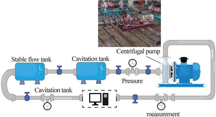
Validation of the centrifugal pump’s hydraulic performance was conducted on a closed-loop test bench at the university, whose layout is shown in Fig. 3.
2.4. Model test verification
The head and efficiency of the centrifugal pump under various stable conditions at different rated speeds were calculated through the full three-dimensional numerical simulation of the centrifugal pump. The calculation formulas used are given by Eqs. (3-5):
where, and – total pressure at the pump outlet and inlet, Pa; – the volumetric flow rate inside the pump, m3/s; – the torque produced by the force acting on the impeller on the pump shaft, N/m; – centrifugal pump speed, r/min.
Fig. 3Performance testing bench for centrifugal pump
The calculated head and efficiency of the centrifugal pump, along with the curves of the calculated and test values, are shown in Fig. 4.
Fig. 4Comparison curves of hydraulic performance of centrifugal pumps
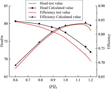
As shown in Fig. 4, the test-derived performance curve of the pump matches well with the trend of the numerical simulation results. Within the range of 0.6-1.2, the relative errors of the head between the numerical simulation calculation value and the test value at each operating point are 0.17 %, 0.88 %, 1.54%, 1.95 %, 1.84 %, 3.00 %, and 3.60 %, respectively. The relative errors of efficiency were 1.75 %, 0.52 %, 0.68 %, 0.53 %, 0.19 %, 0.13 %, and 1.97 % respectively. The head and efficiency obtained from the numerical simulation were relatively close to the test values. The simulated efficiency values of the centrifugal pump under each working condition were slightly higher than the test values, but the overall relative error was smaller. By comparison, it is verified that the numerical pump model developed in this work have high reliability and are applicable to the study of the transient process of variable speed regulation for the centrifugal pump in the following text.
By comparison, it is verified that the numerical pump model developed in this work has high reliability and is applicable to the study of the transient process of variable speed regulation for the centrifugal pump in the following text.
3. Numerical results and analysis
3.1. Setting of monitoring points for centrifugal pumps
Due to the difficulty and high cost of measuring the variable-speed regulation process of the centrifugal pump on the test bench, it is difficult to obtain the computational boundary conditions for numerical simulation during variable-speed regulation. Therefore, by comparing the hydraulic performance test values of the target pump with the numerical simulation calculation values, combined with the results of previous experiments, when the motor speed ratio is not less than 0.6, the motor efficiency decrease is within the acceptable range, and when the speed ratio is less than 0.6, the efficiency decreases [21] significantly. In this paper, computational fluid dynamics analysis software (ANSYS CFX) was used to numerically simulate the acceleration and deceleration processes of variable speed regulation of centrifugal pumps under conditions (0.6-1.0) with an error of no more than 3 % between the numerical simulation values and the test values, thereby being able to simulate the internal flow characteristics of variable speed regulation of centrifugal pumps relatively realistically.
Fig. 5Monitoring points of centrifugal pumps
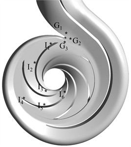
For a better analysis of the pressure conditions on the blades and tongues of the centrifugal pump, the monitoring points for the centrifugal pump were arranged as shown in Fig. 5. Three monitoring points were established on the working surface of the impeller blades, three on the back, and a total of six monitoring points were set on the blades, numbered -; Three monitoring points were set up in the tongue area, numbered -.
3.2. Pressure analysis of the transient phase of variable speed regulation of centrifugal pumps
Fig. 6 shows the internal pressure distribution during the variable-speed regulation transient process of a centrifugal pump. It is evident from Fig. 6 that the pressure at the impeller progressively increases from the blade inlet to the blade outlet. As the rotational speed of the centrifugal pump gradually increases, the pressure inside the pump progressively increases and the pressure gradient increases. When the speed of the centrifugal pump decreases, the pressure inside the pump gradually decreases and the pressure gradient decreases. When 0.4 s, a large high-pressure region is identified on the outlet wall of the centrifugal pump.
Limitation illustration: Only steady hydraulic performance curves are validated via closed-loop test bench in this paper, while transient flow field data during acceleration/deceleration are not measured due to the limitation of high-frequency dynamic pressure testing equipment. At present, published experimental data matching the full linear variable-speed transient process of semi-open double-volute pumps are scarce. Although direct transient verification is absent, the steady-state relative error of head and efficiency is controlled below 3.6 %, which ensures the fundamental reliability of the numerical model. Future work will conduct transient experimental measurement to calibrate the variable-speed flow field results.
Fig. 6Pressure distribution in the centrifugal pump during the transient process of variable speed regulation
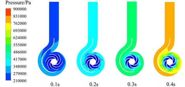
a) The variable speed of the centrifugal pump regulates the pressure distribution inside the pump during the speed-up process

b) The variable-speed adjustment of the pressure distribution in the centrifugal pump during deceleration
To better analyze the pressure characteristics in the variable-speed regulation transient process centrifugal pump, the pressures on the pump tongue, the working surface of the impeller blades, and the back monitoring points were plotted as curves shown in Fig. 7.
As can be seen from Fig. 7(a) that when 0.1 s, as the rotational speed of the centrifugal pump increases, the pressure on the blades gradually increases, and the higher the rotational speed, the faster the pressure inside the pump increases. When 0.1 s, the pressure inside the centrifugal pump suddenly drops as the speed begins to increase. As shown in Fig. 7(b), when 0.1 s, the pressure on the blades gradually decreases as the centrifugal pump speed decreases. When 0.1 s, the pressure inside the pump suddenly increases as the rotational speed begins to change.
Fig. 7Curve of pressure variation in the centrifugal pump during the transient process of variable speed regulation
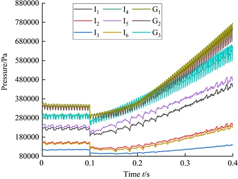
a) Pressure curve inside the centrifugal pump during the speed-up process of variable speed regulation
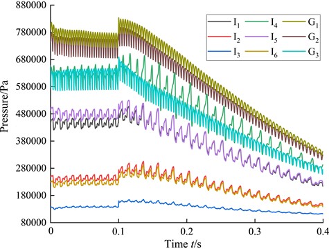
b) Pressure curve inside the centrifugal pump during the speed-down process of variable speed regulation
When adjusting the speed, the area of the tongue is smaller than that of the rest of the volute, and the pressure is greater than that of the blades, but the closer to the impeller flow passage, the smaller the pressure. By comparing Fig. 7(a) and 7(b), it can be observed that the pressure change in the speed-up regulating pump is almost the same as that in the speed-down regulating. When the speed is increased to the rated condition, the pressure in the pump is slightly less than that in the stable operation and speed-down of the centrifugal pump.
3.3. Speed analysis of the transient phase of variable speed regulation of centrifugal pumps
Fig. 8 shows the velocity distribution of the impeller of a centrifugal pump during the transient process of variable speed regulation. The area where flow velocity 9 m/s is defined as the low-speed area, the area where 9 m/s < flow velocity 18 m/s is defined as the medium-speed area, and the area where flow velocity 18 m/s is defined as the high-speed area. As shown in Fig. 8, during the acceleration phase of the centrifugal pump, the fluid velocity within the impeller passages gradually increases as the rotational speed increases. The flow velocity in the impeller channel is relatively high in the region from the blade inlet to the center of the blade outlet. When 0.1 s, there is a medium speed zone. As the speed increases, the medium speed zone gradually transitions to a high speed zone, and the high speed zone gradually expands. Near the blade outlet, the flow velocity in the impeller channel near the working surface of the blade varies greatly. As the rotational speed increases, this region gradually changes from the medium speed zone to the high speed zone. This is because as the rotational speed of the impeller increases, the suction force increases, resulting in a rise in the fluid velocity. However, the flow velocity in the impeller channel near the back of the blade is smaller due to the loss of impeller thrust. Throughout the speed increase process. This area remains in the low-speed zone. During the deceleration process, as the rotational speed decreases, the flow velocity of the fluid in the impeller channels gradually decreases. The fluid in the impeller flow channel in the area from the blade inlet to the center of the blade outlet, due to the reduced impeller speed, the suction force on the fluid decreases, and the fluid velocity changes most significantly in this area and the flow channel area near the working surface of the blade outlet. Near the blade outlet working surface flow channel, the fluid thrust decreases and changes from the high-speed zone to the medium-speed zone.
In summary, during the variable speed process of the centrifugal pump, the fluid velocity changes significantly in the area near the blade outlet working face flow channel and in the impeller flow channel region from the blade inlet to the center of the blade outlet. The flow velocity in the back channel of the blade outlet is the lowest, which is prone to backflow and thus generates vortices, affecting the flow state of the fluid.
Fig. 8Velocity distribution in the transient process of variable speed regulation of centrifugal pumps
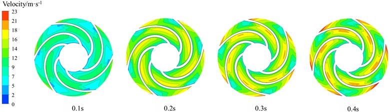
a) Variable speed adjustment of the velocity distribution during the speed-up process of the centrifugal pump
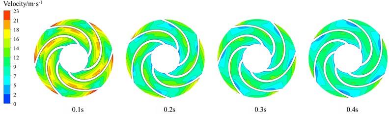
b) Variable speed adjustment of the velocity distribution during the deceleration process of the centrifugal pump
To gain deeper insight into the flow velocity inside the centrifugal pump, time-history curves of fluid velocity at predefined monitoring points are plotted to analyze the transient flow characteristics.
Fig. 9 shows the speed variation curve inside the centrifugal pump during variable speed regulation transient process. As observed from the figure that during the acceleration phase of the centrifugal pump, the flow velocity of the fluid on the blades increases with the increase of speed. With the rise in impeller rotational speed, the fluid velocity at the monitoring point increases first and then decreases, but there is a slight fluctuation near 0.2 s. The fluid velocity at the monitoring point increases first and then decreases, while the fluid velocity at the monitoring point decreases first and then increases. During the deceleration of the centrifugal pump, the fluid velocity on the blades decreases as the rotational speed decreases, but the fluid velocity at the monitoring point exhibits a trend of decreasing first and then increasing. As the impeller speed decreases, the flow velocity at monitoring point decreases first and then increases. Overall, the flow velocity at monitoring point decreases, but between 0.1 s and 0.15 s, the flow velocity increases slightly. The flow velocity at monitoring point decreases first, then increases, and decreases again.
In summary, during the transient variable speed regulation of the centrifugal pump, the fluid velocity adjacent to the blades increases as the centrifugal pump speed increases, but in the working surface area of the blade outlet, the fluid velocity increases due to the decrease in impeller speed. Due to its complex structure and the interaction between the stator and rotor, the flow velocity of the fluid varies at different positions in this area, but the overall flow velocity decreases with the reduction of the centrifugal pump speed, and due to the different flow velocity variations, vortices are prone to form at the tongue, reducing the operational stability of the centrifugal pump.
Fig. 9Curve of speed variation in the centrifugal pump during variable speed regulation transient process
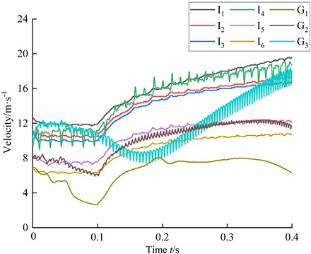
a) The speed curve inside the pump during the variable speed regulation of the centrifugal pump for acceleration
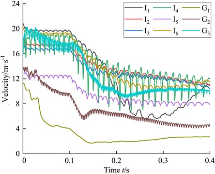
b) The speed curve inside the pump during the variable speed regulation of the centrifugal pump for deceleration
3.4. Vorticity analysis of the transient phase of variable speed regulation of centrifugal pumps
Fig. 10 Vorticity distribution within the centrifugal pump during variable speed regulation transient process. The velocity gradient tensor can be decomposed into the strain rate tensor of the symmetric part and the vorticity , As reported in [22], the values of the antisymmetric part are expressed by Eqs. (6-8):
As shown in Fig. 10, during the speed-up process of the centrifugal pump, as the rotational speed increases, the vortices in the impeller region gradually increase, especially at the inlet of the centrifugal pump. During the deceleration of the centrifugal pump, as the rotational speed decreases, the vorticity in the impeller area gradually decreases. When 0.2 s, the vortex field distribution in the impeller region begins to decrease. When 0.3 s, the vortex field distribution in the impeller region reaches its minimum, and the vortex field distribution at the impeller inlet decreases to the greatest extent, but when 0.4 s, the vortex field distribution is basically consistent with other time periods.
Fig. 10Velocity distribution in the transient process of variable speed regulation of centrifugal pumps
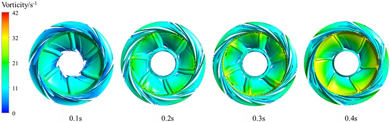
a) The vortex field distribution during the speed-increasing process of the centrifugal pump is regulated by variable speed
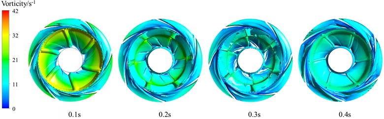
b) The vorticity field distribution during variable speed regulation of the centrifugal pump
To sum up, during the transient variable speed regulation of the centrifugal pump, the vortices in the inlet area of the impeller are the largest, while those in the area near the back of the impeller blades are smaller. Unlike the acceleration phase of the centrifugal pump, during the deceleration phase of the centrifugal pump, due to the decrease in impeller speed, there is a slight backflow of fluid, and the vortex field distribution in the impeller area exhibits a pattern of first decreasing and then increasing.
3.5. Turbulent kinetic energy analysis of centrifugal pump variable speed regulation Transient process
Fig. 11 shows the distribution of turbulent kinetic energy inside the centrifugal pump, during the transient variable-speed regulation of the pump. It is evident from Fig. 11 that during the speed-up process of the centrifugal pump, as the rotational speed increases, the turbulent kinetic energy within the impeller passages elevates progressively. The turbulent kinetic energy exhibits minimal variation in the flow channel near the blade inlet, whereas it changes more prominently in the region between the blade midpoint and the blade outlet. During the deceleration of the centrifugal pump, as the rotational speed decreases, the turbulent kinetic energy in the impeller flow channel diminishes gradually, and the turbulent kinetic energy of the fluid in the passage between the blade and the blade outlet changes significantly.
In summary, during the variable speed regulation of the centrifugal pump, the turbulent kinetic energy of the fluid in the area near the monitoring point within the impeller passages is the greatest, the turbulent kinetic energy of the fluid in the area between the blade center and the blade outlet flow channel changes significantly, and the turbulent kinetic energy of the fluid in the area between the blade inlet and the blade center flow channel is smaller. The turbulent kinetic energy on the blade suction surface is lower than that on the pressure surface. This phenomenon arises because the inlet incidence angle of the centrifugal pump blade adopts a normal incidence design. By comparing the speed-up and speed-down processes of the variable speed regulation of the centrifugal pump, it is concluded that under the identical operating conditions, the turbulent kinetic energy is greater in the speed-down process than in the speed-up process of the centrifugal pump.
Fig. 11Turbulent kinetic energy distribution in the transient process of variable speed regulation of centrifugal pumps
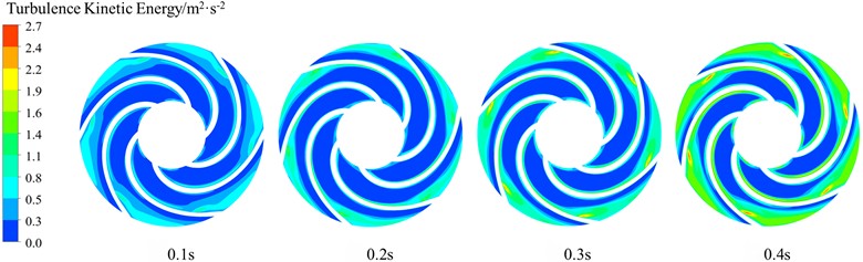
a) Distribution of turbulent kinetic energy during the speed-up process of variable speed regulation of the centrifugal pump
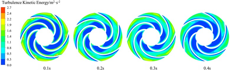
b) Turbulent kinetic energy distribution in the process of variable speed regulation of deceleration of the centrifugal pump
3.6. Streamline analysis of the volute during the transient phase of variable speed regulation of the centrifugal pump
Fig. 12 shows the distribution of flow lines in the volute during the transient process of variable speed regulation of a centrifugal pump. As observed from the figure that vortices are generated in the area near the tongue and near the outlet end of the baffle during the acceleration phase of the centrifugal pump. With increasing rotational speed, the fluid velocity in the vortex-existing area of the volute changes little, but due to the increase in fluid velocity, the backflow phenomenon decreases, leading in a gradual reduction in vortex intensity. During the deceleration phase of the centrifugal pump, vortices are also generated in the area near the tongue inside the volute and at the baffle end close to the tongue outlet. As the rotational speed declines, the intensity of the vortices in the volute increases first and then decreases. When 0.2 s, the vortices in the volute are at their maximum due to the decrease in speed and fluid reflux, and when 0.1 s, they are at their minimum.
In summary, vortices are produced in the tongue part due to the stator-rotor interaction, and vortices are produced within the volute partition due to the collision of fluid conversions. When the centrifugal pump is operating under design conditions, the fluid flow in the vortex-existing area of the volute is relatively stable and the vortex-intensity is minimal. During the deceleration phase of the centrifugal pump, the fluid flow within the volute changes notably, and the intensity of the vortices it generates shows a trend of increasing first and then decreasing, but the overall vortices increase.
Fig. 12Streamline distribution in the volute during the transient process of variable speed regulation of the centrifugal pump
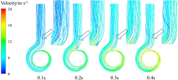
a) Streamline distribution in the volute during the speed-increasing process of the centrifugal pump
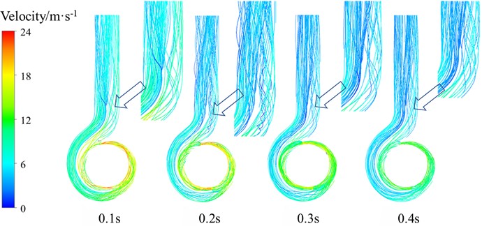
b) Streamline distribution in the volute during the deceleration process of the centrifugal pump
4. Conclusions
This work investigates the transient internal flow features of the speed-increasing and speed-decreasing processes of centrifugal pumps. By comparing and analyzing the speed-increasing and speed-decreasing processes of centrifugal pumps, the following conclusions can be drawn:
1) In the course of the variable speed regulation of the centrifugal pump, the pressure inside the pump changes significantly, the fluid velocity changes greatly in the blade outlet area and blade middle area, the fluid velocity in the blade outlet working surface flow channel is the smallest, the vorticity is the largest at the impeller inlet of the centrifugal pump, the vorticity is the smallest in the blade working surface area, and the turbulent kinetic energy of the fluid changes greatly in the area near the blade middle. Quantitatively, the vortex intensity at impeller inlet is 4 times higher than that on blade working surface, and turbulent kinetic energy changes most drastically in the middle region of blades, which are quantitative rules rarely summarized in previous qualitative researches.
2) By comparing the acceleration process and deceleration process of the centrifugal pump, it is found that the overall pressure inside the pump is smaller during the acceleration process than during the deceleration process. In contrast to the acceleration process, during the deceleration process, the vorticity distribution in the impeller flow channel and the vorticity intensity in the volute show a trend of increasing first and then decreasing, but the overall vorticity intensity increases. This distinct discrepancy of pressure and vortex field under the same rotating speed is defined as flow hysteresis effect, which is a novel finding of this variable-speed study.
3) During the variable-speed regulation of the centrifugal pump, the flow velocity, pressure, vortices and turbulent kinetic energy inside the pump all show obvious transient characteristics, among which the changes in the internal flow characteristics during the deceleration regulation are more obvious. During the variable speed regulation, the pump head, efficiency and associated experimental errors of the centrifugal pump were not large and were within the usable range. Therefore, in practical application, the centrifugal pump studied in this paper can be linearly regulated within the range of 0.6-1.0, but during the deceleration regulation, due to the complex changes in vorticity distribution and vortex intensity, more attention should be paid to the operating conditions of the centrifugal pump when performing the deceleration operation.
References
-
Z. Shen, W. Chu, S. Yan, X. Chen, Z. Guo, and Y. Zhong, “Study of the performance and internal flow in centrifugal pump with grooved volute casing,” Modern Physics Letters B, Vol. 34, No. 25, p. 2050268, Sep. 2020, https://doi.org/10.1142/s0217984920502681
-
K. Wang et al., “Experimental investigation on multi-condition performance of ultra-high-speed high-pressure fuel centrifugal pumps,” (in Chinese), Journal of Huazhong University of Science and Technology (Natural Science Edition), Jul. 2025, https://doi.org/10.13245/j.hust.250652
-
G. Li, J. Zhang, J. Mao, S. Yuan, and J. Jia, “Numerical investigation of the transient flow and frequency characteristic in a centrifugal pump with splitter blades,” Journal of Thermal Science, Vol. 30, No. 2, pp. 562–573, Dec. 2020, https://doi.org/10.1007/s11630-020-1391-2
-
Q. Pang et al., “A study on energy loss and transient flow characteristics of a large volute centrifugal pump during power-off process under cavitation conditions,” Journal of Marine Science and Engineering, Vol. 13, No. 10, p. 1973, Oct. 2025, https://doi.org/10.3390/jmse13101973
-
G. Hongyu, J. Wei, W. Yuchuan, T. Hui, L. Ting, and C. Diyi, “Numerical simulation and experimental investigation on the influence of the clocking effect on the hydraulic performance of the centrifugal pump as turbine,” Renewable Energy, Vol. 168, pp. 21–30, Dec. 2020, https://doi.org/10.1016/j.renene.2020.12.030
-
H. Bozorgasareh, J. Khalesi, M. Jafari, and H. O. Gazori, “Performance improvement of mixed-flow centrifugal pumps with new impeller shrouds: numerical and experimental investigations,” Renewable Energy, Vol. 163, pp. 635–648, Aug. 2020, https://doi.org/10.1016/j.renene.2020.08.104
-
Y. Lu, L. Tan, X. Zhao, and C. Ma, “Experiment on cavitation-vibration correlation of a centrifugal pump under steady state and start-up conditions in energy storage station,” Journal of Energy Storage, Vol. 83, p. 110763, Feb. 2024, https://doi.org/10.1016/j.est.2024.110763
-
Y.-L. Zhang, Y.-Y. Ji, and Y.-J. Zhao, “Deep analysis of the transient behavior of centrifugal pumps during startup and shutdown,” Measurement and Control, Vol. 55, No. 3-4, pp. 155–163, May 2022, https://doi.org/10.1177/00202940211064234
-
D. Arumugam and K. Sivasailam, “Pressure fluctuation study in the stages of a multistage pump at best efficiency points under various operating speeds,” Journal of Engineering Research, Vol. 10, No. 2, pp. 227–247, Oct. 2021, https://doi.org/10.36909/jer.10257
-
M. Mansour, S. Kopparthy, and D. Thévenin, “Investigations on the effect of rotational speed on the transport of air-water two-phase flows by centrifugal pumps,” International Journal of Heat and Fluid Flow, Vol. 94, p. 108939, Jan. 2022, https://doi.org/10.1016/j.ijheatfluidflow.2022.108939
-
B. Liang, M. Wang, Q. Zhang, Z. Wang, and P. Jiang, “Influence of wall roughness on pressure distribution and performance of centrifugal dredge pumps,” Intelligent Marine Technology and Systems, Vol. 1, No. 1, pp. 4–4, Sep. 2023, https://doi.org/10.1007/s44295-023-00004-1
-
T. Parikh, M. Mansour, and D. Thévenin, “Investigations on the effect of tip clearance gap and inducer on the transport of air-water two-phase flow by centrifugal pumps,” Chemical Engineering Science, Vol. 218, p. 115554, Feb. 2020, https://doi.org/10.1016/j.ces.2020.115554
-
X. Ma et al., “Transient characteristic analysis of internal flow during centrifugal pump startup process,” Journal of Mechanical and Electrical Engineering, Vol. 38, pp. 1546–1551, Dec. 2021.
-
L. Cheng, H.-F. Huang, Y.-L. Zhang, Y.-J. Zhao, and X.-Q. Jia, “Transient characteristics and differences of a prototype centrifugal pump under different startup modes,” Journal of the Chinese Institute of Engineers, Vol. 48, No. 7, pp. 907–927, Oct. 2025, https://doi.org/10.1080/02533839.2025.2491432
-
W. Ye, Z. Zhu, Z. Qian, and X. Luo, “Numerical analysis of unstable turbulent flows in a centrifugal pump impeller considering the curvature and rotation effect,” Journal of Mechanical Science and Technology, Vol. 34, No. 7, pp. 2869–2881, Jul. 2020, https://doi.org/10.1007/s12206-020-0619-0
-
G. Yang, D. Zhang, X. Yang, B. Xu, X. Zhao, and B. P. M. van Esch, “Study on the flow pattern and pressure fluctuation in a vertical volute centrifugal pump with vaned diffuser under near stall conditions,” Journal of the Brazilian Society of Mechanical Sciences and Engineering, Vol. 44, No. 4, Mar. 2022, https://doi.org/10.1007/s40430-022-03411-3
-
J. Chen, Y. Li, and X. Liu, “Experimental investigation on vibration characteristics of double-suction centrifugal pumps under multi-operational conditions,” Journal of Jiangsu University (Natural Science Edition), Vol. 42, pp. 526–532+553, Aug. 2021.
-
L. Wang et al., “Transient flow field and impeller stress characteristic analysis during the shutdown process of large pumping station centrifugal pumps,” China Rural Water and Hydropower, No. 1, pp. 120–125, Apr. 2025.
-
B. Zhao, Z. Dong, and Y. Fu, “Effects of stage-by-stage startup on internal and external flow characteristics in centrifugal pump systems,” Fluid Machinery, Vol. 52, No. 5, pp. 40–46, May 2024.
-
R. Gangipamula, P. Ranjan, and R. S. Patil, “Study on fluid dynamic characteristics of a low specific speed centrifugal pump with emphasis on trimming operations,” International Journal of Heat and Fluid Flow, Vol. 95, p. 108952, Feb. 2022, https://doi.org/10.1016/j.ijheatfluidflow.2022.108952
-
J. Dong et al., “Analysis of the effect of variable speed regulation on sediment wear characteristics of centrifugal pumps,” China Rural Water and Hydropower, No. 8, pp. 201–204+208, Oct. 2016.
-
C. Ning et al., “Effects of blade number on internal flow characteristics of a composite impeller under constant solidity condition,” Journal of Mechanical Engineering, No. 14, pp. 320–327, Dec. 2021.
About this article

This research was financially supported by the National Natural Science Foundation of China (Grant No. 52009114); Xianyang Major Science and Technology Innovation Special Project (Grant No. L2025-ZDKJ-ZDGG-KTH-004); and Xianyang ’Scientist and Engineer’ Team Construction Project (Grant No. L2024-CXNL- KJRCTD-DWJS-0037).
The datasets generated during and/or analyzed during the current study are available from the corresponding author on reasonable request.
Wei Dong: conceptualization, methodology, funding acquisition, writing-review and editing. Haichen Zhang: methodology, software, writing-original draft preparation. Shijie Yao: methodology, software.
The authors declare that they have no conflict of interest.