Abstract
Aiming at the problem that the scraper conveyor in the steeply inclined working face is prone to sliding instability and causing safety accidents under the coupling load of the shearer, a safety mechanics analysis of sliding was carried out to provide quantitative theoretical support for the anti-sliding safety control of the equipment. By combining theoretical modeling, numerical simulation and experimental testing, a load transfer model of the shearer cutting and a sliding mechanics model of the n-segment series scraper conveyor were established. The force balance equation of a single middle trough and the critical criterion for the overall sliding of the system were derived. The EDEM and RecurDyn co-simulation was used to analyze the influence of key factors such as two coal and rock strengths of 1.2 MPa and 2.6 MPa and working face inclinations from 30° to 60° on the sliding characteristics of the scraper conveyor. A 1:5 scale dynamic load sliding test bench was built, and the dynamic load of the shearer was simulated by a shaker. The rationality of the theoretical model was verified through multi-condition tests. The results show that the shearer load acting section is the weak force section between the sections of the scraper conveyor. When there is no hydraulic support restraint, as the working face inclination increases from 30° to 60°, the force between the sections of the shearer acting section increases from 150 N to 350 N, with an increase of 133 %. At a 45° inclination, the sliding driving force of the shearer acting section has exceeded the maximum static friction force in the unrestrained state, and there is a risk of local sliding, but the overall system remains stable. After applying the hydraulic support restraint force, the force between the sections of the shearer acting section at a 60° inclination decreases by more than 48 %, and the maximum static friction force of the acting section can completely counteract the sliding driving force, eliminating the risk of local sliding and achieving the overall sliding stability of the scraper conveyor. The research reveals the sliding instability mechanism of the scraper conveyor under the coupling load of the shearer, clarifies the key parameters for sliding safety control, and provides important theoretical and experimental basis for the anti-sliding safety design and on-site control of the scraper conveyor in steeply inclined working faces.
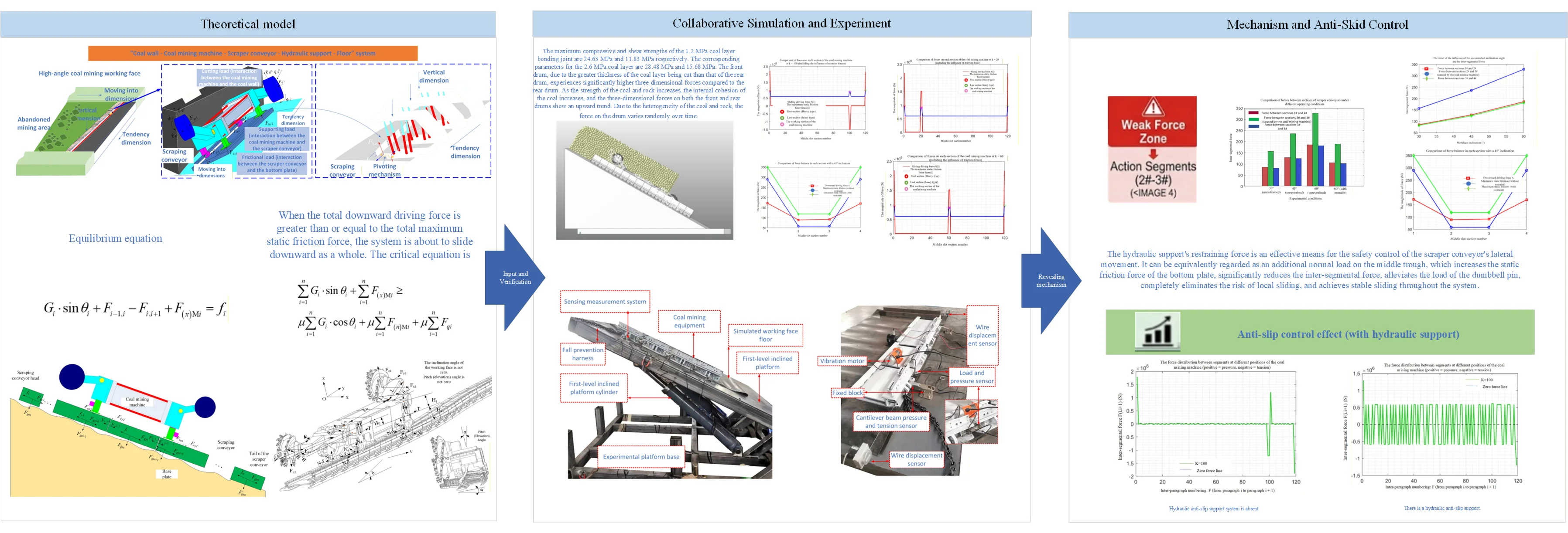
Highlights
- Shearer cutting load drives local force deterioration of scraper conveyor. With working face inclination rising from 30° to 60°, the force in the action section rises by 133%, more inclination-sensitive than the non-action section, and higher coal-rock strength amplifies sliding risk further.
- A sliding mechanical model of n-segment series scraper conveyor is constructed to clarify the critical condition of overall system sliding. Without hydraulic support, the action section has local sliding risk while the system remains globally stable.
- Hydraulic support force is the key measure for sliding control under high inclination. At 60° inclination, it reduces force in the action section by over 48%, eliminates local sliding risk completely and achieves full-area stable anti-sliding.
1. Introduction
For the mining of steeply inclined working faces, problems such as the sliding and tipping of coal mining equipment are obstacles that hinder the improvement of production efficiency and also increase the probability of safety accidents. The sliding of the scraper conveyor causes the connection length between the head of the machine and the transfer machine to be too long, resulting in phenomena such as the scraper conveyor pulling back coal and coal accumulation at the head. In severe cases, it can even block the end safety exit, causing production to stop. Additionally, the sliding of the scraper conveyor sometimes causes the hydraulic support to slide downward as well, resulting in continuous collisions and squeezes of supports in the lower part of the working face, affecting the advancement speed of the working face, and even reducing the control ability of the hydraulic support on the roof, triggering roof collapse accidents, and seriously affecting the safety production of the working face [1-3].
The reasons for the sliding instability of the coal mining equipment on the steeply inclined working face include not only the static load components acting downward along the inclined surface due to the self-weight of the equipment and the loaded materials, but also the dynamic loads such as the cutting resistance of the coal mining machine and the driving load for movement. In addition, the influence of the coal powder medium on the friction characteristics of the random rough bottom of the working face and the middle trough bottom of the conveyor, the influence of the space forms such as the over-bent sections of the scraper conveyor and the undulations of the bottom plate, as well as the interaction between the pushing mechanism of the hydraulic support and the middle trough of the scraper conveyor, all these factors will have an impact on the sliding instability of the coal mining equipment on the steeply inclined working face.
Gao Sheng [4] constructed a dynamic stability model for the scraper conveyor in a high-inclination fully mechanized mining face. By studying the reverse inertial force and working resistance encountered by the scraper conveyor during operation, he obtained the discriminant formula for the stability conditions of the scraper conveyor. Yang Ke et al. [5] compared the force characteristics of the hydraulic supports in a large-height fully mechanized mining face and, based on the stability control characteristics of the high-inclination hydraulic supports, established two instability modes of overturning and sliding. They obtained the friction coefficient between the hydraulic support and the immediate roof, as well as the relationship between the instability of the hydraulic support and the coal seam inclination. Zhang Jinfu [6] analyzed the force state of the scraper conveyor in the high-inclination working face and made a judgment on the upward movement and downward sliding of the conveyor. Based on on-site feedback, he found methods and measures to control the upward movement and downward sliding. Wan Dongfeng et al. [7] applied the anti-tilt and anti-slip mechanism of the high-inclination hydraulic support to the inclined fully mechanized mining face and conducted research and design to ensure the control stability during its operation. Li Xiaomeng [8] constructed a mechanical model for the stability analysis of the supports in the steeply inclined fully caving mining field and obtained the criteria for the non-sliding, non-tilting, and non-twisting instability of the supports. At the same time, he obtained the mechanical boundary conditions for the sliding, tilting, and twisting of a single support and the reasonable roof pressure for maintaining stability. Zhao Xufeng [9] studied the adaptability and stability of the mining equipment in the coal seam with a high inclination and obtained the critical conditions for the stability of the “three machines” without sliding or tilting. Fan Zhizhong [10] et al. based on the principle of “upward sliding and downward tilting” of the “three machines” in the fully mechanized mining face, revealed that the occurrence of “upward sliding and downward tilting” of the mining equipment was due to reasons such as the deviation angle between the coal conveyor's coal transportation direction and the mining advancement direction of the fully mechanized face. Mao Hanlin [11] et al. designed a rotation and tilt adjustment scheme and process to address the problem of scraper conveyor sliding. Qu Qiuyang et al. [12] et al. conducted in-depth research on the anti-tilt and anti-sliding problem of the fully mechanized equipment in the high-inclination mining face and installed anti-tilt mechanisms specifically on the scraper conveyor and hydraulic supports. Feng Yufeng et al. [13] et al. started from the reasons for the sliding of the scraper conveyor and the tilting of the supports in the fully mechanized mining face and studied the pseudo-slope parameters and equipment configuration in the mining face, solving the problem of scraper conveyor sliding. Wang Wei et al. [14] and Li Dazheng et al. [15] combined theory and practice and used anti-tilt devices in the fully mechanized mining face and carried out technical modifications for anti-tilt of the “three machines”.
At the international research level, Kotwica et al. from Poland [16] conducted dynamic simulation and experimental tests on the meshing and sliding problem between the walking system of the shearer and the toothed track of the scraper conveyor in steeply inclined working faces. They quantified the sliding characteristics and load fluctuation laws of the toothed track and walking wheels under the curved section of the scraper conveyor and the undulating floor conditions, and revealed the influence mechanism of the geometric form of the meshing pair on the sliding behavior, providing a basis for the flexible optimization design of the conveyor track. However, this study did not involve the overall sliding instability of the conveyor along the inclined plane. Sul et al. from Australia [17] through immersion experiments and corrosion kinetics analysis, revealed the influence law of the water environment in the working face on the friction and wear characteristics of the scraper conveyor chain. They found that reverse osmosis treated water would aggravate the pitting behavior of the chain, thereby changing the dynamic tension distribution of the scraper chain and indirectly affecting the anti-sliding stability of the conveyor during operation. This study focused on the influence of material corrosion on friction characteristics, but did not involve the overall sliding behavior of the machine under the coupling of multiple factors such as coal powder medium and floor roughness. Nemcik et al. from Australia [18] established a dynamic numerical model of fault slip in deep mining based on FLAC3D, quantified the transient mechanical response of structural surface slip under dynamic load disturbance, and revealed the velocity weakening effect and energy release law of the friction interface under dynamic load impact. Their mechanical analysis method of dynamic load-friction coupling slip provides a reference for the study of dynamic load instability of coal mining equipment, but this study did not conduct targeted analysis based on the structural characteristics and constraint conditions of longwall coal mining equipment. Szewerda et al. from Poland [19] established a multi-body dynamic model of the scraper conveyor under inclined conditions, analyzed the influence of the inclination direction and transportation direction on the dynamic tension distribution of the scraper chain, and clarified that the asymmetric distribution of chain tension caused by the increase in inclination is an important cause of conveyor operation instability. However, their research only focused on the steady-state operation conditions under static inclination and did not involve the sliding instability evolution process under transient disturbances such as shearer cutting dynamic load and random floor undulation. Overall, international research on longwall mining in steeply inclined coal seams in the past has mainly focused on equipment structure optimization and process improvement in countries such as the former Soviet Union, Germany, and Poland. In the past five years, research has mostly focused on the friction and wear of equipment components, local meshing sliding, and the mechanical behavior of structural surfaces under dynamic load disturbance. Although this has provided basic methods and data support for equipment stability research, a systematic study on the dynamic load sliding instability mechanism of the shearer-scraper conveyor-hydraulic support system in steeply inclined working faces has not yet been formed.
Domestic and foreign scholars have conducted fruitful research on infrared identification of coal and rock and adaptive control of mining equipment, achieving significant progress in sensor fusion, layer prediction, and friction and wear of key components. However, for the special working condition of steeply inclined working faces, there are currently no systematic reports on the “dynamic load sliding instability” mechanism of equipment considering the cutting dynamic load of the shearer, the dynamic constraints of the support-conveyor system, and the random friction characteristics of the floor. In view of this, based on existing research, this paper aims to break the limitations of traditional static balance analysis through a combination of theoretical analysis, multi-condition simulation, and experimental testing. Compared with existing research, the novelty of this paper lies in: treating the “three machines” system as a dynamic whole affected by dynamic load disturbance and uncertain constraints, and revealing the intrinsic mechanism of the evolution from steady-state balance to dynamic load instability by capturing the friction behavior law of the shearer cutting transient. The research results will provide more comprehensive and scientific theoretical support for the research and development, precise selection, and intelligent anti-overturning and anti-sliding of coal mining equipment in steeply inclined working faces.
This paper explores the characteristic laws of the transient friction behavior of coal mining equipment sliding on steeply inclined working faces under the coupling of multiple factors and uncertain constraints through a combination of theoretical analysis, experimental testing, virtual simulation, and numerical calculation. It reveals the key mechanical mechanisms of dynamic load sliding instability evolution of coal mining equipment and proposes criteria for dynamic load sliding instability of coal mining equipment on steeply inclined working faces under different working conditions. This research provides a theoretical basis for the development, selection, and anti-toppling and anti-slip of coal mining equipment on steeply inclined working faces. The limitations of this study are manifested in the simplified equivalent treatment of support constraints, the difference between excitation loads and actual cutting, and the insufficient consideration of complex environmental coupling (such as water environment, random floor friction). In the future, digital twin and real-time monitoring technology should be combined to achieve active intelligent anti-slip control, and fatigue analysis and structural optimization design should be carried out for weak links such as the middle trough connection parts.
2. Construction of the sliding mechanical model for scraper conveyors considering coal mining loads
The sliding instability of coal mining equipment on steeply inclined working faces is a nonlinear multi-body dynamics problem involving multi-dimensional interaction among multiple systems (such as “top roof - coal mining machine - scraper conveyor - hydraulic support - bottom roof”) under the constraints of the random roughness of the working face floor and the uncertainty of the equipment spatial form, as well as the multiple excitations from the vibration and impact of the coal mining operation.
The hydraulic support and the middle trough of the scraper conveyor are connected through the push rod. There is an interaction between the hydraulic support and the scraper conveyor, providing resistance, i.e., a constraining force, for the sliding of the scraper conveyor. The coal mining machine is connected to the scraper conveyor through the toothed track and the smooth shoe. The forces exerted by the coal mining machine during cutting and moving will ultimately act on the scraper conveyor. Therefore, the reaction force of the coal mining machine when cutting coal and rock will induce the instability of the scraper conveyor's sliding [20].
The schematic diagram illustrating the multi-system and multi-dimensional interaction relationship of “top roof - mining equipment - scraper conveyor - hydraulic support - bottom plate” in the steeply inclined longwall working face is shown in Fig. 1.
Fig. 1Schematic diagram of multi-system and multi-dimensional interaction relationships in a large-angle longwall working face
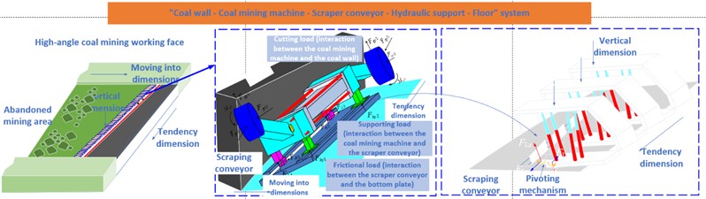
Therefore, this paper first establishes a load transmission model for the cutting load of the coal mining machine acting on the scraper conveyor through the sliding shoe, and then establishes a sliding mechanical model for the scraper conveyor considering the coal mining load.
2.1. Coal mining machine cutting load transmission model
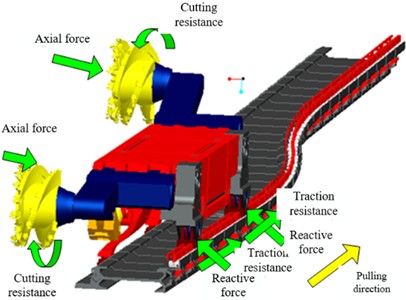
When the coal mining machine moves along the chute of the curved section of the scraper conveyor and completes the coal and rock cutting operation, it will be subjected to multiple forces such as cutting resistance, axial thrust of the coal wall on the drum, traction resistance, and counter-reaction force of the sliding shoe. The spatial force state is shown in Fig. 2.
Fig. 2Space force diagram of shearer
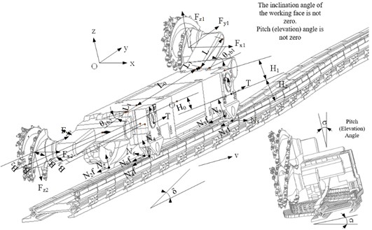
Facing the coal wall direction, with the center of the entire machine of the coal mining machine as the coordinate origin , a three-dimensional coordinate system - is established: The direction passing through the origin and parallel to the width of the coal mining machine body, pointing to the goaf area, is the positive half-axis of the -axis; the direction passing through the origin and parallel to the length of the coal mining machine body, pointing to the traction movement direction, is the positive half-axis of the -axis; the direction perpendicular to the plane and upward is the positive half-axis of the -axis. Based on this coordinate system, this paper constructs a unified spatial mechanical model for the cutting operation of the coal mining machine when the working face inclination is non-zero and there are cases of downward or upward mining, as shown in Fig. 3.
Fig. 3Space mechanics model of shearer beveling feeding
The necessary and sufficient condition for a spatial force system to reach equilibrium is that the algebraic sum of the projections of all forces on the , , and coordinate axes is zero, and the algebraic sum of the torques of all forces about the three coordinate axes is also zero. That is, the resultant vector of the force system and the principal moment about any point are both zero.
Based on the equilibrium conditions of the spatial force system, by using the force equilibrium and moment equilibrium equations, the force equilibrium relationships in the , , and axes directions, as well as the moment equilibrium relationships in the , , and planes, are respectively established. Through this, the mathematical model of the entire coal mining machine in the inclined cutting feed-in condition is derived:
where, represents the component force of a single traction mechanism of the coal mining machine along the -axis, in Newtons; represents the component force of a single traction mechanism of the coal mining machine along the -axis, in Newtons; represents the self-weight of the coal mining machine, in Newtons; represents the supporting reaction force of the front and rear guide shoe and the smooth shoe ( 1, 2, ..., 6), in kilonewtons; and are the supporting reaction forces of the front and rear smooth shoe along the -axis, in Newtons; and are the supporting reaction forces of the front and rear guide shoe along the -axis, in Newtons; and are the supporting reaction forces of the front and rear guide shoe along the -axis; represents the position dimension along the -axis of each force application point, in meters; represents the position dimension along the -axis of each force application point, in meters; represents the position dimension along the -axis of each force application point, in meters; and are the axial forces of the front and rear drums, in Newtons; and are the cutting resistance of the front and rear drums, in Newtons; and are the advancing resistance of the front and rear drums, in Newtons; represents the body swing angle caused by the different cross-offsets of the front and rear sliding shoes, in degrees; and are the swing angles of the front and rear rocker arms of the coal mining machine, in degrees; represents the dip angle of the coal seam in the working face, in degrees; represents the pitch angle of the coal mining machine, in degrees. represents the friction coefficient, which refers to the sliding friction coefficient between the guide shoe and the smooth shoe of the coal mining machine and the contact surface of the scraper conveyor (the middle trough plate or the guide rail).
2.2. Research on sliding mechanics of inclined sprocket conveyor
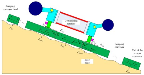
The mechanical model for the sliding of the scraper conveyor considering the load of the coal mining machine is shown in the Fig. 4.
(1) Research Object and Structural Simplification.
1) The scraper conveyor system composed of sections of parallel middle slots, each section is simplified as a rigid body, and the sections are connected by dumbbell pins. It is assumed that the dumbbell pins only transmit axial forces along the length of the slots and have no additional bending moments.
2) End slot: The middle slot of the 1st section is the machine head, and the middle slot of the nth section is the machine tail. Their weights are and respectively, and and ( 2, 3,..., ).
3) Standard middle slot: The self-weight of the middle slots from the 2nd to the th section is all .
3) Coal mining machine: The two sliding shoes of the coal mining machine act on the adjacent 2 sections of middle slots, which are designated as slot k and slot (), and only normal pressure and axial force are applied to these two sections.
4) Hydraulic support constraint force: Each middle slot of the scraper conveyor is connected to the hydraulic support through the push rod, and this push rod can provide a constraint force for the downward movement of the scraper conveyor. It is denoted as ( 1, 2,..., ). This constraint force is related to the supporting force of the hydraulic support and the top plate. The greater the supporting force between the hydraulic support and the roof, the greater the frictional resistance, and the greater the constraint force it can provide. Therefore, in this paper, this constraint force is equivalent to the additional normal pressure acting on the middle slot of the -th section, and it needs to be converted into a braking friction force by multiplying the static friction coefficient and included in the total friction force calculation.
Fig. 4Presents the construction of the sliding mechanical model of the scraper conveyor considering the load of the coal mining machine
(2) Coordinate System and Core Parameters.
This paper adopts segmented independent coordinate systems to adapt to the different bottom plate inclination angles of each section’s central groove, and establishes a local coordinate system for each section's central groove separately to ensure the accuracy of the force analysis:
Set the axis of the local coordinate system: along the length direction of the central groove of the -th section (downward is the positive direction, consistent with the inclination angle of this section); set the axis of the local coordinate system: perpendicular to the surface of the central groove of the -th section, pointing towards the bottom plate as the positive direction.
The core parameters involved in Figs. 4 and the following text are as follows:
: The inclination angle of the plane where the middle slot of the -th section is located relative to the horizontal plane. Usually, the bottom plate of the fully mechanized mining face is uneven, which leads to different inclination angles for each section’s middle slot, i.e., . The positive direction is defined as downward inclination along the slot.
: The self-weight of the middle slot of the -th section (when 1, , it is the tail of the machine and the tail of the machine; when 2 to , it is the standard type).
: The static friction coefficient between all sections' middle slots and the bottom plate (all values are set uniformly; if the bottom plate is soft or hard, can be changed as needed, and the value can be adjusted accordingly).
: The normal reaction force of the bottom plate on the -th section’s middle slot.
: The maximum static friction force between the -th section’s middle slot and the bottom plate, with the direction opposite to the axis.
: The axial force exerted by the -th line pan section on the -th line pan section; : The reaction force exerted by the -th section on the -th section, satisfying Newton's third law (i.e., ); The compressive or tensile nature of the force between adjacent line pan sections is determined entirely by the difference in their sliding tendencies, according to the following sign conventions: : Indicates that the force exerted by the -th section on the -th section is a compressive force (pressure); : Indicates that the force exerted by the -th section on the -th section is a tensile force (tension); : Indicates that the sliding tendencies of the two adjacent sections are identical, resulting in no mutual interaction force.
: The axial force of the coal mining machine on the -th section’s middle slot ( direction, traction or resistance, when the coal mining machine has no effect, ).
: The normal pressure of the coal mining machine’s sliding shoe on the -th section’s middle slot. When there is no effect of the coal mining machine, it is 0.
: The hydraulic support constraint force, which is equivalent to the additional positive pressure of the -th section’s middle slot, with a value range ≥ 0, and is set to 0 when there is no restraint requirement.
(3) Central trough equilibrium equation.
For any -th section of the central trough ( 1, 2,..., ), a separate force analysis is conducted. Based on the local coordinate system, a static equilibrium equation is established, mainly focusing on the force balance in the direction, the sliding direction. The force balance in the direction of a single section of the central trough needs to consider: the component of self-weight sliding force, the force between the two sections of the central trough in front and behind, the axial force of the coal mining machine, and the static friction force. The equation is as follows:
The following explanations are required for the above equation:
1) For the first section (): Since there is no preceding slot, . Usually, the first section has no effect from the coal mining machine, machine1 = 0.
2) For the last section (): Since there is no following slot, 0. Usually, the last section has no effect from the coal mining machine, machinen = 0.
3) For the middle sections (2~): If it is not the section where the coal mining machine acts (), then machinei = 0, machinei = 0.
4) Static friction force constraint: When not slipping, ; when slipping occurs, in the opposite direction to the sliding trend); when slipping happens, .
(4) Critical conditions for overall system sliding.
The sliding of the scraper conveyor system composed of middle slots is divided into local sliding and overall sliding. This paper mainly studies the overall sliding to determine the safety of the equipment in different working conditions of the fully mechanized mining face, as well as the local sliding of each middle slot, in order to analyze the force conditions of the dumbbell pins between the middle slots. The critical condition of the scraper conveyor system is: the total downward driving force of all segments of the system ≥ the total maximum static friction force.
1) Total sliding driving force :
The total sliding driving force is the algebraic sum of all the sliding driving forces (when is negative, it will counteract the total driving force and become the anti-slip force):
2) Total Maximum Static Friction Force :
The total maximum static friction force is the sum of all the individual maximum static friction forces . Each segment’s normal reaction force has been included in the constraint force (additional positive pressure) of the hydraulic support:
3) Overall sliding critical condition:
When the total downward driving force is greater than or equal to the total maximum static friction force, the system is about to slide downward as a whole. The critical equation is:
By increasing the total maximum static friction force on the right side, the critical condition becomes more difficult to meet, thereby inhibiting overall sliding. If the overall sliding risk is known (the total driving force on the left side is too large), the constraint force can be adjusted so that the total maximum static friction force on the right side is greater than the total driving force on the left side, achieving anti-slip control.
3. Simulation analysis of sliding mechanics of scraper conveyor considering the vibration of coal mining operations
Using the EDEM discrete element software and the RECURDYN dynamic simulation software, a multi-system interaction dynamic model of the coal mining machine and the scraper conveyor, as well as a dynamic friction mechanics model of the scraper conveyor and the working face floor, were constructed.
3.1. Simulation analysis of cutting load for coal mining machines operating on steep inclined work surfaces
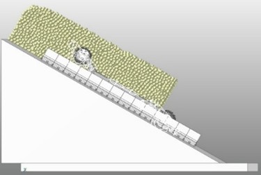
This paper uses RecurDyn and EDEM to jointly establish a cutting operation model for a large-angle coal mining machine, obtaining the cutting load of the coal mining machine when it operates on a large-angle working face. A coal mining machine dynamics model for solving the three-dimensional forces on the rollers and different viscosity coal layer models are jointly set up for numerical simulation, which can solve the three-dimensional forces on the front and rear rollers. After the independent establishment of the EDEM and RecurDyn simulation models, the joint simulation method is used to achieve the collaborative work of the two software. The joint simulation effect is shown in the Fig. 5.
When the geometric model of the coal seam is filled with coal particles, the cohesion key parameters are defined in the software, and cohesion keys are generated between the coal particles. The cohesion key parameters consist of unit normal stiffness, unit tangential stiffness, maximum compressive strength, and maximum shear strength. The calculation formula is:
where – unit normal stiffness, unit is N/m3; – unit tangential stiffness, unit is N/m3; – maximum compressive strength, unit is Pa; – maximum shear strength, unit is Pa; – tensile strength, unit is Pa; – shear modulus, unit is Pa; – radius, unit is m; – viscosity, unit is MPa; – friction angle, unit is (º); – Poisson’s ratio.
Fig. 5Joint simulation model of EDEM and RecurDyn
This paper analyzes the coal-rock strengths at 1.2 MPa and 2.6 MPa. The unit normal stiffness and unit tangential stiffness of the bonding bonds in the 1.2 MPa coal layer and the 2.6 MPa coal layer are 13.549×10⁹ N/m3 and 4.909×10⁹ N/m3 respectively. To highlight the different viscosity properties of the coal, the maximum compressive strength and maximum shear strength are selected. The maximum compressive strength and maximum shear strength of the bonding bonds in the 1.2 MPa coal layer are 24.63 MPa and 11.83 MPa respectively; the maximum compressive strength and maximum shear strength of the bonding bonds in the 2.6 MPa coal layer are 28.48 MPa and 15.68 MPa respectively.
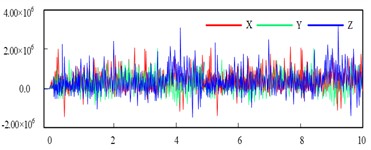
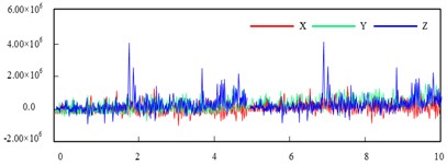
When the coal mining machine is extracting the coal seam, the drum will be subjected to the force of the coal seam, resulting in acceleration between the drum and the rocker arm. Therefore, the extraction force on the drum is the prerequisite for the acceleration of the drum and the rocker arm. The three-dimensional forces on the drum when extracting coal seams with viscosities of 1.2 MPa and 2.6 MPa are shown in the Fig. 6-7. When the coal mining machine is extracting the coal seam, the drum will be subjected to the force from the coal seam, resulting in acceleration between the drum and the rocker arm. Therefore, extracting the force on the drum is the prerequisite for analyzing its vibration characteristics. Fig. 6 shows the three-dimensional force-time curve of the front drum when the mining intensity is 1.2 MPa for the coal seam. In the figure, the horizontal axis represents time (unit: s), and the vertical axis represents the force on the drum (unit: N). Among them, the direction corresponds to the axial force of the drum, the direction corresponds to the resistance in the forward direction of the machine body, and the direction corresponds to the cutting resistance in the vertical direction.
From the figure, it can be seen that when mining a coal seam with a viscosity of 1.2 MPa, the root mean square values of the -direction forces on the front and rear rollers are 2.974×10⁵ N and 1.499×10⁵ N respectively, the root mean square values of the -direction forces on the front and rear rollers are 3.158×10⁵ N and 2.306×10⁵ N respectively, and the root mean square values of the -direction forces on the front and rear rollers are 4.130×10⁵ N and 2.659×10⁵ N respectively. When mining a coal seam with a viscosity of 2.6 MPa, the root mean square values of the -direction forces on the front and rear rollers are 4.222×10⁵ N and 2.004×10⁵ N respectively, the root mean square values of the -direction forces on the front and rear rollers are 3.629×10⁵ N and 3.309×10⁵ N respectively, and the root mean square values of the -direction forces on the front and rear rollers are 4.276×10⁵ N and 3.002×10⁵ N respectively. The thickness of the coal seam mined by the front roller is greater than that of the rear roller, resulting in the three-dimensional forces on the front roller being greater than those on the rear roller; as the viscosity of the coal seam increases, the internal cohesion of the coal seam increases, causing the three-dimensional forces on the front and rear rollers to increase as well; the coal seam is uneven, resulting in the forces on the rollers changing randomly over time. Through analysis, it is found that the force distribution pattern of the rollers is consistent with the actual situation and has certain feasibility. In the following, this paper will use the above simulation results to analyze the sliding characteristics of the scraper conveyor under the load of the coal mining machine.
Fig. 6Forces on the front and rear drums for mining coal seams at 1.2 MPa
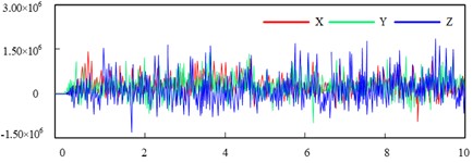
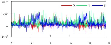
Fig. 7Forces on the front and rear drums for mining coal seams at 2.6 MPa
3.2. Analysis of the sliding characteristics of the belt conveyor under the load of the coal mining machine cutter
Based on the sliding mechanical model of the large-angle scraper conveyor established in Section 1.2 and the research analysis results obtained in Section 2.1, the cutting load of the coal mining machine is studied to investigate the sliding characteristics of the scraper conveyor under the action of the cutting load of the coal mining machine. The influence laws of different working inclinations, the operation of the coal mining machine at different positions, and the up and down operation of the coal mining machine on the sliding of the scraper conveyor are analyzed.
(1) The influence of hydraulic supports on the sliding of scraper conveyors.
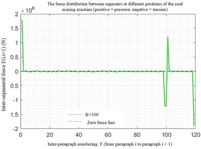
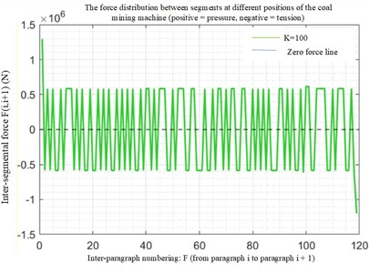
Set the positive pressure of the hydraulic supports. When the positive pressure is 0, it is considered that the hydraulic supports have no effect on the scraper conveyor. The pressure between each section of the middle trough of the scraper conveyor is as follows when there is or is not the effect of the hydraulic supports:
The calculation results show that the hydraulic support has a significant impact on the pressure between the middle sections of the scraper conveyor. In Fig. 8(a), when the coal mining machine is near the 100th section, the pressure between the middle sections increases significantly, which is likely to exceed the bearing limit of the connecting dumbbell pins. However, after adding the effect of the hydraulic support, the pressure between the middle sections of the scraper conveyor does not change significantly when the coal mining machine is at different positions.
(2) The influence law of the coal mining machine's operation position on the stability of the scraper conveyor.
By placing the coal mining machine at the 20th, 60th, and 100th sections of the scraper conveyor respectively, the downward driving force and static friction at different positions of the coal mining machine were obtained for comparison.
Fig. 8Forces between the middle sections of the scraper conveyor when and without the presence of hydraulic supports
a) Without the effect of hydraulic supports
b) With the effect of hydraulic supports
Fig. 9Comparison of downward driving force and static friction at different positions of the coal mining machine
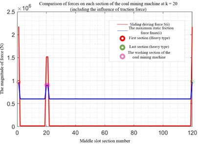
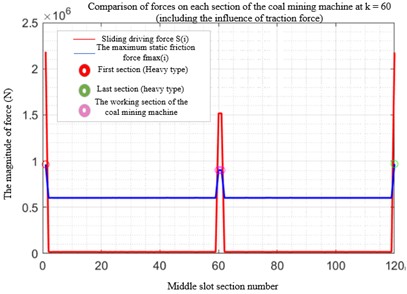

The coal mining machine at different positions on the scraper conveyor will cause an increase in the local sliding driving force and the maximum static friction force. The increase in the sliding driving force is due to the cutting load of the coal mining machine, and the increase in the maximum static friction force is caused by the weight of the coal mining machine acting on the scraper conveyor, thereby increasing the normal pressure. Although the local sliding driving force is greater than the static friction, the overall sliding driving force is much smaller than the static friction, so it cannot cause the scraper conveyor to slip.
(3) The influence law of the coal mining machine’s up and down operation on the stability of the scraper conveyor
When the coal mining process is set at position 100, the data of the tension force between the middle trough sections, the sliding driving force and the friction force are shown as in the Fig. 10.
Fig. 10Data of tension and pressure as well as friction force between the middle sections of the conveyor belt during the downward movement of the coal mining machine
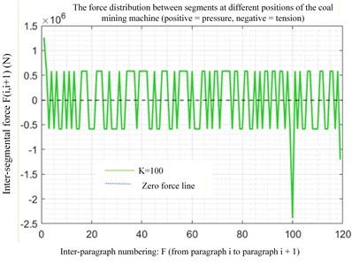
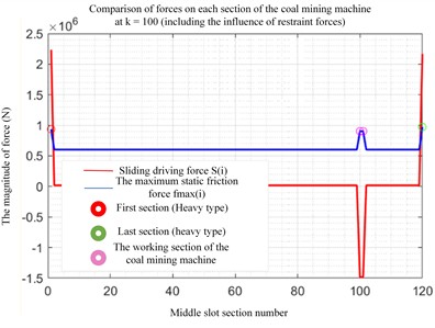
During the upward movement of the coal mining machine, both its own weight and the cutting load are directed downward along the working face. The sliding driving force is generally downward, and it mainly relies on the hydraulic support to provide the counterforce. However, during the downward movement of the coal mining machine, the cutting load along the working face is upward, causing a sudden change in tension and compression stress between the middle sections of the trough.
4. Experimental study
4.1. Construction of the experimental platform
A large-angle mining equipment dynamic load sliding test platform with a similar ratio of 1:5 was independently developed. The test platform uses hydraulic cylinders to adjust the platform angle to simulate the inclination angle of the comprehensive mining face. A model of the scraper conveyor was manufactured according to a similar ratio, and the scraper conveyor has a complete power mechanism, scraper, chain, etc. The hydraulic support currently only uses fixed blocks to simulate. The cantilever beam tension/compression sensor is used to simulate the sliding mechanism, which is connected to the middle trough of the scraper conveyor, enabling the scraper conveyor to form a process bending section. The constrained state of the hydraulic support on the base plate is simulated using the fixing force of the fixed block. Various simulated base plate materials are laid on the platform base plate to simulate different roughness of the base plate. Due to the difficulty in power issues and the simulation of cutting coal and rock, the mining machine on the test platform does not realistically cut coal and rock. The dynamic load of the mining machine is simulated using an exciter. Through experimental testing, the sliding laws and conditions of the scraper conveyor under different excitation and constraint conditions are compared with the theoretical analysis results to verify the feasibility of the theoretical method, making the theoretical research method more applicable. The self-developed large-angle mining equipment dynamic load sliding test platform is shown in Fig. 11.
Fig. 11Experimental platform for dynamic load sliding of self-made inclined coal mining equipment with large angle
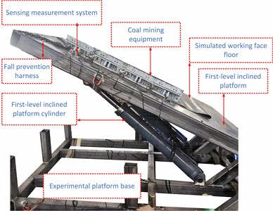
a) Overall structure
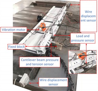
b) Sensing measurement system
4.2. Analysis of test results
This test is based on a 4-section scraper conveyor dynamic load sliding test bench with a 1:5 similarity ratio. The exciter is used to simulate the coal mining dynamic load, and the fixed block is used to simulate the hydraulic support restraining force. The inter-segment force under different operating conditions is collected through the inter-segment pressure sensors, and the sliding characteristics of the scraper conveyor are analyzed using the theoretical mechanics model. The following will conduct quantitative and qualitative analysis on the results of 3 groups of tests to reveal the influence laws of inclination angle and hydraulic support restraining force on the inter-segment force and sliding stability of the scraper conveyor.
(1) Comparison analysis of inter-segment forces under different operating conditions.
The changes in the inter-segment forces of 1#-2#, 2#-3#, and 3#-4# sections under four operating conditions (30° without restraint, 45° without restraint, 60° without restraint, and 60° with restraint) are presented in a columnar form, as shown in the Fig. 12.
Fig. 12Comparison of forces between sections of scraper conveyor under different operating conditions
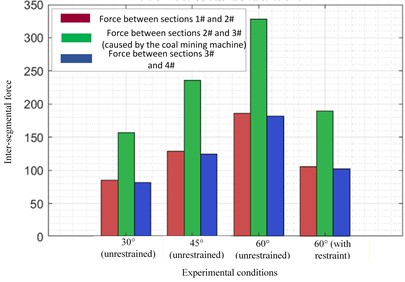
Under the same working conditions, the force between the 2#-3# sections is much greater than that between the 1#-2# and 3#-4# sections. In the 60° uncontrolled working condition, the force between the 2#-3# sections is close to 350 N, while the forces between the 1#-2# and 3#-4# sections are approximately 200 N. The reason is that the vibration load of the coal mining machine directly acts on the adjacent 2#-3# sections, which not only bears the self-weight sliding component but also adds the axial dynamic load of the coal mining machine, causing a sudden increase in the force on the inter-sectional dumbbell pins, making this section the core weak section of the scraper conveyor inter-sections.
In the uncontrolled condition, as the working face inclination angle increases from 30° to 60°, the forces between each section all show a linear upward trend. Among them, the force between the 2#-3# sections increases the most, from approximately 150 N to 350 N, with an increase of 133 %. This is because the increase in inclination angle significantly enhances the sliding component of the self-weight of the middle section along the inclined direction, and the inter-section requires a greater axial force to balance the sliding trend, resulting in a synchronous increase in the tension and compression loads of the dumbbell pins.
Under the 60° condition, after applying the hydraulic support restraint force, the forces between each section all significantly decrease. Among them, the force between the 2#-3# sections decreases from 350 N to approximately 180 N, a reduction of over 48 %; the forces between the 1#-2# and 3#-4# sections also decrease by more than 40 %. Because the hydraulic support restraint force is equivalent to the additional positive pressure on the middle section, by increasing the static friction force of the bottom plate, it counteracts part of the sliding driving force, reduces the axial force transmission between the sections, and effectively alleviates the load on the dumbbell pins.
(2) Trend Analysis of the Influence of Unrestrained Inclination Angle on Inter-segment Forces.
For the range of 30° to 60° without restraint, the continuous trend of the forces between the three segments as the inclination angle changes is shown in the Fig. 13.
Fig. 13Trend of the influence of inclination angle without restraint on the force between segments
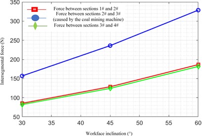
The force between each section shows a monotonically increasing trend as the inclination angle increases, and the growth rate gradually increases, indicating that the influence of the inclination angle on the force between sections has an amplification effect. That is, the greater the inclination angle, the greater the increase in the force between sections caused by the increase in the unit inclination angle. From 30° to 45°, the increase in the force between sections 2# and 3# is approximately 100 N; from 45° to 60°, the increase reaches 200 N. This is because the component of self-weight sliding force is proportional to the sine value of the inclination angle, and the greater the inclination angle, the faster the growth rate of the sliding force component.
The growth rate of the force between sections 2# and 3# is significantly higher than that of the other two sections, and the broken line of this section is always at the top, indicating that the sensitive nature of the working section of the coal mining machine to the inclination angle change is much higher than that of the non-working section. This means that under the condition of a large inclination angle, the force between sections of the coal mining machine will quickly approach the allowable load of the dumbbell pin, becoming the primary risk point for the failure of the scraper conveyor structure, and also the key controlled section for preventing sliding and structural damage on site.
(3) Comparison analysis of the sliding driving force and the maximum static friction force at 45° inclination angle for each section.
At a 20° inclination angle, the numerical relationship of the sliding driving force, the maximum static friction force without restraint, and the maximum static friction force with restraint in sections 1#, 2#, 3#, and 4# is shown in the Fig. 14.
Fig. 14Comparison of sliding driving force and maximum static friction force for each section at a 45° inclination angle
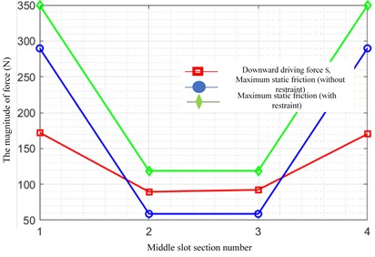
The downward driving force of the 2# and 3# troughs is significantly greater than the maximum static friction force without restraint. The downward driving force of the 2# trough is approximately 90 N, while the static friction force without restraint is only 60 N, meeting the local slip condition; for the 1# and 4# troughs, due to greater self-weight, the normal reaction force is large, and the static friction force without restraint is much greater than the downward driving force, remaining in a stable state. Overall, although the scraper conveyor without restraint has local slip, the total downward driving force is less than the total static friction force, and no overall slip occurs, which is consistent with the theoretical model derivation conclusion.
The restraint force of the hydraulic support increases the normal reaction force, significantly enhancing the maximum static friction force of each trough. At this time, the static friction force of the 1# and 4# troughs increases to around 350 N, and that of the 2# and 3# troughs increases to around 120 N. The downward driving force of all trough sections is less than the maximum static friction force, completely eliminating the risk of local slip and achieving global anti-slip stability of the scraper conveyor.
5. Conclusions
This paper focuses on the sliding safety mechanics problem of a scraper conveyor with a large inclination angle under the load coupling effect of the coal mining machine. It conducts a systematic study by combining theoretical modeling, numerical simulation, and experimental testing methods, clarifying the sliding instability rules and key points of safety control for the scraper conveyor:
1) The cutting load of the coal mining machine is the main cause that leads to the deterioration of the local force of the scraper conveyor. The load application section is the core weak area where the system experiences force. Without the support of hydraulic supports, when the working face inclination angle increases from 30° to 60°, the force between the action segments of the coal mining machine increases by 133 %, and its sensitivity to the inclination angle change is significantly higher than that of the non-action segments; the increase in coal and rock strength will increase the cutting load of the coal mining machine, further amplifying the force and sliding risk of the weak section.
2) The established sliding mechanical model of the n-segment series-connected scraper conveyor can effectively characterize its sliding force characteristics. The critical condition for the overall sliding of the system is that the total downward driving force is greater than or equal to the total maximum static friction force. Without the supporting force of hydraulic supports, there is a local sliding risk in the action segment of the coal mining machine, but the total driving force of the system is less than the total static friction force, and the system can still remain stable as a whole.
3) The supporting force of the hydraulic support is a key and effective means for the safe control of the sliding of the scraper conveyor under high inclination conditions. It can increase the static friction force of the bottom plate by equivalently increasing the normal pressure of the middle trough. Under a 60° inclination condition, applying the supporting force of the hydraulic support can reduce the force between the action segments of the coal mining machine by more than 48 %, significantly enhance the anti-sliding bearing capacity of the weak section, completely eliminate the local sliding risk, and achieve the stable anti-sliding of the system throughout the area.
This study reveals the sliding instability mechanical mechanism of the scraper conveyor with a large inclination angle under the load coupling of the coal mining machine, providing important theoretical and experimental basis for the anti-slip safety design, structural optimization, and on-site working condition regulation of the scraper conveyor on a large inclination working face.
References
-
Y. P. Wu, K. Z. Liu, D. F. Yun, P. S. Xie, and H. W. Wang, “Research progress on the safe and efficient mining technology of steeply dipping seam,” (in Chinese), Journal of China Coal Society, Vol. 39, No. 8, pp. 1611–1618, 2014.
-
Z. Wang and W. T. Jiao, “Cause analysis and control method of ’upward running and downward sliding’ of scraper conveyor in near horizontal fully-mechanized face,” (in Chinese), Coal Engineering, Vol. 54, No. 8, pp. 48–53, 2022.
-
Y. P. Wu, D. F. Yun, P. S. Xie, H. W. Wang, and D. Lang, “Longwall fully-mechanized mining in steeply dipping seam: progress, practice and scientific problems,” (in Chinese), Journal of China Coal Society, Vol. 45, No. 1, pp. 24–34, 2020.
-
S. Gao, “Stability analysis and control of scraper conveyor in fully-mechanized coal face with large inclination angle,” (in Chinese), Coal Technology, Vol. 37, No. 7, pp. 218–220, 2018, https://doi.org/10.13301/j.cnki.ct.2018.07.079
-
K. Yang, X. L. Chi, and S. Liu, “Instability mechanism and control of hydraulic support in fully mechanized longwall mining with large dip,” (in Chinese), Journal of China Coal Society, Vol. 43, No. 7, pp. 1821–1828, 2018, https://doi.org/10.13225/j.cnki.jccs.2017.0949
-
J. F. Zhang, “Technology to control scraper conveyor sliding down in high inclined fully mechanized coal mining face,” (in Chinese), Coal Engineering, No. 12, pp. 56–57, 2012.
-
D. F. Yun, B. Gu, Y. P. Wu, P. Z. Su, T. L. Li, and H. W. Wang, “Application effect and technical improvement of shearer and scraper conveyor in steeply dipping seam,” (in Chinese), Coal Science and Technology, Vol. 44, No. 12, pp. 118–123, 2016, https://doi.org/10.13199/j.cnki.cst.2016.12.021
-
X. M. Li, “Study on surrounding rock control technology and support stability in steeply inclined fully-mechanized caving face,” China University of Mining and Technology (Beijing), Beijing, China, 2016.
-
X. F. Zhao, “Study on combined mining of steeply inclined thin coal seam group,” Taiyuan University of Technology, Taiyuan, China, 2018.
-
Z. Z. Fan, “Up and down moving mechanism and control of false-inclined mining equipment with large mining height,” (in Chinese), Coal Mining, Vol. 23, No. 6, pp. 36–39, 2018, https://doi.org/10.13532/j.cnki.cn11-3677/td.2018.06.009
-
H. L. Mao and C. W. Hu, “Analysis of anti-slipping technology of the ’three machines’ in greater tilt angle fully mechanized mining face,” (in Chinese), Modern Mining, Vol. 31, No. 5, pp. 17–19+33, 2015.
-
Q. Y. Qu et al., “Research on stability and safety control technology of equipment in large dip angle and high cutting working face,” (in Chinese), Coal Engineering, Vol. 47, No. 5, pp. 61–64, 2015, https://doi.org/10.11799/ce201505021
-
Y. F. Feng, S. C. Tian, and J. W. Xu, “Brief analysis on anti-slip technology for fully mechanized working face with large inclined angle,” (in Chinese), Mining and Processing Equipment, Vol. 38, No. 19, pp. 17–20, 2010, https://doi.org/10.16816/j.cnki.ksjx.2010.19.006
-
W. Wang, Y. Y. Zhang, L. Zhang, B. B. Zhang, W. P. Huang, and L. Gao, “Stability technology for fully mechanized mining equipments in steeply inclined working face under condition of broken floor,” (in Chinese), Safety in Coal Mines, Vol. 45, No. 10, pp. 62–64, 2014.
-
D. Z. Li, H. L. Gao, and H. W. Wang, “Anti-slip and anti-drag technology for equipment in long fully-mechanized top-coal caving face with large inclination angle,” (in Chinese), Coal Science and Technology, Vol. 41, No. S2, pp. 75–77, 2013, https://doi.org/10.13199/j.cnki.cst.2013.s2.049
-
K. Kotwica, G. Stopka, M. Kalita, D. Bałaga, and M. Siegmund, “Impact of Geometry of Toothed Segments of the Innovative KOMTRACK Longwall Shearer Haulage System on Load and Slip during the Travel of a Track Wheel,” Energies, Vol. 14, No. 9, p. 2720, May 2021, https://doi.org/10.3390/en14092720
-
J.-H. Sul, B. Probyn, B. Donnelly, L. Piyathilaka, and S. Jeong, “Investigating Effects of Reverse Osmosis-Treated Water on the Corrosion Rate of Chains in Armoured Face Conveyor for Longwall Mining,” Mining, Metallurgy and Exploration, Vol. 40, No. 6, pp. 2193–2204, 2023, https://doi.org/10.1007/s42461-023-00862-7
-
J. Nemcik et al., “Dynamic model of fault slip and its effect on coal bursts in deep mines,” in Proceedings of the 2021 Resource Operators Conference, pp. 186–193, 2021.
-
K. Szewerda, J. Świder, and K. Herbuś, “Analysis of impact of longitudinal inclination of a chain conveyor on dynamical phenomena during operation,” MATEC Web of Conferences, Vol. 94, p. 01010, Jan. 2017, https://doi.org/10.1051/matecconf/20179401010
-
Y. P. Wu, “Controlling pattern for dynamic stability of system ’Roof-Support-Floor,” (in Chinese), Journal of China Coal Society, Vol. 32, No. 4, pp. 341–346, 2007, https://doi.org/10.13225/j.cnki.jccs.2007.04.002
About this article

This research was funded by the National Natural Science Foundation of China (Grant No. 52304134).
The datasets generated during and/or analyzed during the current study are available from the corresponding author on reasonable request.
Chunxue Xie: writing the original manuscript, preparation, formal analysis, obtaining the funds. Xiangyu Chen: conceptualization, method design. Zhixiang Liu: supervision, writing, review, editing.
The authors declare that they have no conflict of interest.