Abstract
Increasing heat transfer in double-pipe heat exchangers (DPHEs) is an interesting topic due to challenges that still remain to be solved, especially when working under low-to-moderate flow rate regimes where poor mixing and thermal boundary layers reduce the effectiveness of convection. Despite numerous studies conducted on the basis of metal-foam and insert-type enhancement methods, existing research mostly covers completely-filled or simplified partially-filled cases. The present work numerically investigates thermo-hydraulic performance of a countercurrent DPHE using various structured metal-foam inserts installed in the annulus region. In particular, a three-dimensional CFD model of the studied geometry was successfully validated with previously reported experimental data with deviations not exceeding ±5 % for the average Nusselt number and ±7 % for the friction factor. In simulations, hot water flows inside the inner pipe at temperature 75 °C and 3 L/min, whereas cold water enters the annulus at temperature 30 °C with flow rates of 1 to 9 L/min, equivalent to Reynolds numbers of 205-1845. In total, nine geometries were considered including a smooth basecase, fully filled foam geometry, circular ring foam baffles, continuous three-strips foam geometry, as well as five interrupted three-strips foams with 5, 7, 9, 11, and 13 interruptions, respectively. For all cases, copper foam with porosity 0.9 and pores density 40 PPI was used, while water thermophysical properties were assumed constant. It was found that inserting structured metal-foam increases heat transfer due to mixing effect and repeated disruption/regeneration of thermal boundary layer. As compared with the smooth base case, the fully filled metal-foam geometry showed the largest improvement in heat transfer performance by providing up to 15 times higher values of the average Nusselt number. Nevertheless, the interrupted strips foam designs demonstrated the best thermo-hydraulic characteristics in terms of trade-off between enhanced heat transfer and increased pressure drop penalty. In particular, the interrupted foams led to approximately 1.5-3 times higher friction factor than the smooth geometry, while performance evaluation factor PEF equaled approximately 2.8. Therefore, it can be concluded that interrupting structured metal-foam inserts could be considered promising passive enhancement approach for low-to-moderate Reynolds number DPHEs.
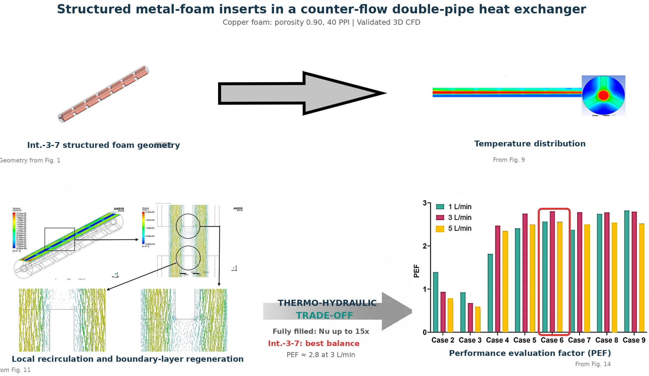
Highlights
- The Int.-3-7 configuration delivered the best thermo-hydraulic balance, with optimum performance near a 3 L/min cold-water flow rate.
- A validated 3D CFD model compared nine structured copper-foam layouts in a counter-flow double-pipe heat exchanger.
- Fully filled foam increased the average Nusselt number by up to 15 times, but imposed the largest hydraulic penalty.
- Interrupted foam strips promoted mixing and repeated thermal-boundary-layer redevelopment with moderate flow resistance.
- Interrupted layouts raised friction by about 1.5-3 times yet achieved a peak performance evaluation factor of approximately 2.8.
1. Introduction
There are many thermal applications, such as refrigeration, where heat exchangers are essential. The optimization of energy consumption and the improvement of system performance rely on the efficient transfer of heat between fluids. Double-pipe heat exchangers (DPHEs) are a common configuration, preferred for their simple construction, ease of maintenance, and operating flexibility [1-5]. However, practical applications, particularly under laminar or transitional flow regimes, constrain their overall heat transfer efficacy. This limitation principally arises from the restricted heat transfer surface area of the concentric tubes and the formation of a permanent thermal boundary layer on their internal surfaces. The study outlines various enhancement strategies, encompassing active, passive and hybrid approaches, as viable remedies to these limitations [6-8]. Passive methods, including surface roughening, the insertion of twisted tapes, and the utilization of porous or metal-foam materials, are particularly appealing, as they can effectively augment convective heat transfer without consuming energy [9, 10]. The integration of metal foams has garnered tremendous attention because of their great surface area-to-volume ratio, open-cell structure, and enhanced thermal conductivity, which leads to turbulent nano-structure transformation and improved energy transfer within the flow channels. Therefore, metal foam inserts have become an efficient means of enhancing heat transfer and thermal uniformity in compact heat exchangers [11, 12]. Metal foams have received considerable interest as potential passive augmentation devices because of their great surface area-to-volume ratio and interconnected pores, which also serve as a favorable pathway for heat transport. Alhusseny et al. [13] combined rotating metal-foam guiding vanes and a foam spread on the conducting surface of a pipe a DPHE. Their 3D steady laminar model included centrifugal buoyancy, Coriolis effects, a generalized porous-media momentum form, thermal dispersion, and local heat non-equilibrium (LTNE) between fluid and solid. Results revealed that the rotating-foam design significantly enhanced exchanger effectiveness when compared to fully foam-filled configurations. The numerical study by Ali and Ghashim [14] examined four foam arrangements under a uniform wall heat flux: filled, partially filled near the wall, partially filled at the core, and split into three sections. The research established that the partially filled near-wall configuration is optimal for thermal performance when employing a Forchheimer-extended Darcy model combined with the LTNE and k–ε models. In contrast, the filled foam, while offering the most significant overall heat transfer, also resulted in the most substantial pressure drop, highlighting the critical trade-off between thermal and hydraulic performance. In a heat-pipe radiator, Hen et al. [15] replaced the fins with copper metal foam (15 PPI) to examine the thermal flow performance across a range of air velocities and heating power. The research highlights the reduction of the overall thermal resistance by around a quarter of its value when compared to a conventional finned heat pipe radiator. In addition, the overall performance is significantly enhanced with the metal foam radiator, especially for 13, 000. The flow and heat transfer characteristics of a heat exchanger of a staggered tube bank (ten rows) with metal foam are studied by Chen et al. [16] using 3D numerical simulation. The work employs seven types of stainless steel foam, with porosities ranging from 0. 85 to 0. 95 and pore densities between 30 and 60 PPI. The findings demonstrate that the overall heat transfer rate is more responsive to porosity (). Jadhav et al. [17] analyzed numerically the influence of using a partially filled aluminum foam within a horizontal conduit on the enhancement of heat transmission while maintaining an acceptable pressure drop. The simulation covers six modelling scenarios of metallic foam configurations under various pore density and porosity. The CFD simulation utilized the Darcy-Forchheimer and k–ω models under LTNE conditions. The maximum thermal-performance factor of approximately 2. 93 at 4500 for the 30 PPI foam exhibited a declining trend with increasing flow rate. Athith et al. [18] used ANSYS Fluent software to model a partially filled metal foam heat exchanger, aiming to enhance heat transmission and reduce pressure loss. Three types of foams are employed: aluminum, copper, and nickel, each exhibiting pore densities of 20 and 40 PPI. The foams were assessed at different heights. Numerical studies indicate a 5. 68-fold increase in heat transfer using copper foam at elevated intake velocities relative to a non-porous channel. A 50 % metal foam filled porous tube improved heat transfer and reduced pressure drops. The relationship between critical operating parameters and thermal performance of a DPHE with twisted tri-lobe tubes and water as the working fluid was studied numerically by Sheikhi et al. [19]. In the analysis, the researchers used the turbulent - shear-stress transport model, and the finite volume method to solve the governing equations. A hybrid ANN-GA optimization was also used and achieved the best PEC of approximately 1. 16, associated with a low outer-Re, high inner-Re, and a large outer-twist ratio in the configuration. This study, building on the research of Zhang et al. [20], introduces innovative DPHEs using C-shaped serpentine channels to improve flow mixing and convective heat transfer via chaotic advection. The suggested shape of DPHEs markedly enhances heat transfer relative to the conventional design, with peak total heat transfer coefficients of 679. 41 and 677. 75 W/mK, respectively, at 500. Aljubury et al. [21] experimentally compared the hydraulic and thermal performance of metal foam twisted tape (MFTT) and traditional twisted tape (TTT) in a DHPE. Reynolds numbers between 16, 300 and 32, 500 were employed to assess the heat transfer efficacy of TTT and MFTT inserts with twist ratios (/ = 3. 6, 5. 2, and 6. 8), as indicated by the Nusselt number (Nu) and friction factor. Results show that both MFTT and TTT enhance heat transfer inversely with twist ratio, with MFTT exhibiting superior performance, achieving Nusselt number increases of 175-230 % over TTT and 275-500 % over the clear tube. The performance of DPHEs augmented with copper-foam inserts of varying pore densities and geometries was studied numerically and experimentally by Zuhair et al. [22, 23]. Both studies found that foam shapes that were partially filled or cut worked best to improve their thermal and hydraulic properties. The optimal design, featuring 40 PPI and 180°, achieved the most significant gains, yielding around a 32 % improvement in heat transfer rate and over 117-146 % increase in Nusselt number relative to smooth tubes, thus validating the efficacy of customized porous-foam constructions. The effects of using integrated metal foams with circular, triangular, and square apertures alongside CuO-water Nano fluids on the thermal and hydraulic performance of DPHE were analysed by Nati et al. [24, 25]. Their results show that perforated metal foams infused with 1%CuO Nano fluid enhance the Nusselt number by 184 %. Moreover, circular-hole topologies achieve the highest PEC (about among the evaluated geometries. But the majority of published work is restricted to full or simplified partial filled porous arrangements; and there has been little focus on engineered foam topologies tested at common operating conditions. The importance of structural configuration and material distribution in governing system behavior has been recognized across several engineering applications [26]. In thermo-fluid systems, and particularly in enhanced heat exchangers, the spatial arrangement of porous inserts can significantly alter local mixing, boundary-layer redevelopment, and pressure-drop characteristics. This view is consistent with previous findings showing that insert architecture and material distribution strongly influence overall thermal and hydraulic performance [13]. Recent studies on enhanced double-pipe heat exchangers have shown that numerical modelling alone is insufficient unless it is supported by suitable thermo-hydraulic performance criteria [27, 28]. In particular, the assessment of porous and metal-foam inserts should account for both the gain in heat transfer and the associated increase in flow resistance. For this reason, the present study employs the Nusselt number, friction factor, and performance evaluation factor (PEF) as complementary indicators to provide a balanced comparison of the investigated configurations [27, 28]. More broadly, validated numerical modelling and performance interpretation under varying operating conditions are widely adopted across engineering disciplines for the analysis of complex systems [26]. In such applications, the predictive value of a model depends not only on numerical accuracy, but also on its ability to explain how design variables and operating parameters govern system response. The same methodological perspective is adopted in the present study to evaluate the thermo-hydraulic behavior of structured metal-foam inserts in double-pipe heat exchangers. Reliable performance interpretation in engineering systems is significantly strengthened when numerical modelling is supported by experimental validation [29]. In this context, the present study adopts a validated CFD framework to assess the thermo-hydraulic behaviour of structured metal-foam inserts in double-pipe heat exchangers, thereby providing a more reliable basis for design-oriented performance evaluation. Similarly, studies from other engineering disciplines have shown that modelling assumptions, validation methodology, and operating or loading conditions can strongly influence system response and the reliability of performance evaluation [30, 31]. This broader methodological perspective supports the present use of a validated CFD framework under multiple operating conditions for assessing the thermo-hydraulic behavior of structured metal-foam inserts in double-pipe heat exchangers. A brief review of relevant contributions further supports the methodological basis of the present work. Previous studies have shown that structural configuration and porous-material distribution can strongly affect thermal and hydraulic behaviour in enhanced exchanger systems [13, 26]. In addition, recent investigations have highlighted that modelling should be accompanied by suitable performance criteria in order to balance heat-transfer enhancement against hydraulic penalty [27, 28, 25]. More broadly, validated modelling and careful interpretation of system response under varying conditions are well-established principles in engineering analysis [29, 30, 31]. Accordingly, the present study adopts a validated CFD framework and evaluates the investigated configurations using the Nusselt number, friction factor, and performance evaluation factor (PEF) to provide a balanced thermos-hydraulic assessment. Overall, the available literature confirms that metal-foam and insert-based enhancement techniques can significantly improve heat-transfer performance in double-pipe heat exchangers. Their main merits include increased surface area, stronger flow mixing, and improved thermal effectiveness. However, these advantages are often accompanied by increased hydraulic resistance, and many previous studies have been limited to fully filled or simplified partial-fill configurations, making it difficult to identify an optimal balance between thermal enhancement and pressure-drop penalty. In addition, direct comparative assessment among different structured foam topologies under practical operating conditions remains limited. These observations define the main novelty of the present work, which lies in the systematic thermo-hydraulic comparison of multiple structured copper-foam layouts using a validated CFD framework. Despite the reported benefits of metal-foam and insert-based enhancement techniques, several drawbacks remain in the existing body of work. Many previous studies have focused on fully filled or simplified partial-fill porous arrangements, which often lead to high hydraulic resistance and do not allow a clear assessment of how foam topology alone affects thermo-hydraulic performance. In addition, direct comparison among structured interrupted layouts under practical low-to-moderate flow conditions has remained limited. The present study addresses these shortcomings by employing a validated three-dimensional CFD framework to systematically compare multiple structured copper metal-foam configurations and identify layouts that provide a more favorable balance between heat-transfer enhancement and hydraulic penalty. Most of the previous studies only reported either the thermal performance (e.g., Nusselt number) enhancement or the hydraulic penalty (e.g. Friction factor or pressure drop) separately; it is difficult to find a quantitatively optimal design. To fill those gaps, the current study establishes a validated three-dimensional CFD model for a counter-flow DPHE including conjugate heat transfer, Darcy-Forchheimer porous-medium modeling and SST – turbulence treatment and applies the tool to nine cases (one smooth baseline configuration and eight foam-enhanced). Validated numerical modelling has become an important tool for analyzing enhanced double-pipe heat exchangers because it enables detailed examination of local flow and heat-transfer mechanisms while reducing the need for extensive prototyping. In such systems, thermo-hydraulic performance is governed not only by insert topology and porous-medium distribution, but also by operating conditions such as flow rate and Reynolds number. Therefore, a validated CFD framework is particularly useful for clarifying how geometric and operating parameters jointly affect heat transfer enhancement, hydraulic resistance, and overall engineering performance. The key novelty of this work is the topologically controlled comparison of ring-type, continuous-strip and interrupted strip foam topologies; including interrupted strip topologies with mid-axial cuts which share the same volume and mass metrics as the ring foams. These mass-and volume-equivalent design constraints make it feasible to judge the isolated effect of foam spatial distribution and interruption pattern on thermal-boundary-layer redevelopment, mixing intensity, and flow resistance. An additional contribution is the quantitative comparison of all possible alternatives on the basis of a single thermo-hydraulic criterion defined in terms of Nusselt number, friction factor and performance evaluation factor (PEF), which gives practical design guidelines for compact energy-saving tubular heat exchangers. To provide a clearer comparative basis for the present study, the most relevant previous investigations on porous- and insert-enhanced double-pipe heat exchangers are summarized in Table 1.
Table 1Comparative review of previous studies on porous- and insert-enhanced double-pipe heat exchangers
Reference | Approach and configuration | Conditions / metrics | Key outcome and relevance |
Alhusseny et al. [13] | 3D numerical study of rotating metal-foam structures in a DPHE | Laminar rotating-flow conditions; effectiveness and thermo-fluid behavior | Showed that structural arrangement strongly affects exchanger performance, but focused on rotating rather than stationary structured foam layouts |
Ali and Ghashim [14] | Numerical comparison of fully filled and partially filled metal-foam arrangements | Uniform wall heat flux; heat-transfer enhancement and pressure drop | Partial filling gave a better thermal–hydraulic balance, while full filling increased heat transfer at the cost of much higher pressure drop |
Jadhav et al. [17] | Numerical study of partially filled high-porosity metal-foam configurations in a pipe | Moderate Reynolds-number range; thermal-performance factor and hydraulic penalty | Confirmed that foam arrangement and pore density strongly influence the thermo-hydraulic trade-off, but not within a full multi-topology DPHE framework |
Sheikhi Azizi et al. [19] | Numerical + AI optimization of twisted tri-lobe DPHE geometry | Multiple operating conditions; Nusselt number, friction factor, PEC | Identified optimized enhanced geometry, but the work addressed tube-shape enhancement, not structured porous inserts |
Aljubury et al. [21] | Experimental study of metal-foam twisted tape (MFTT) and traditional twisted tape in a DPHE | 16,300-32,500; Nu and friction factor | MFTT improved heat transfer more than traditional tape, but with added hydraulic resistance; no comparison among several structured foam layouts |
Rabeeah et al. [22] | Numerical–experimental study of copper-foam baffles in a DPHE | Water flow; heat-transfer rate, Nusselt number, and hydraulic behavior | Reported strong enhancement, including about 32.4 % heat-transfer improvement and about 117 % Nu increase in an optimal case, but only for a limited baffle family |
Faal et al. [23] | Numerical study of copper-foam baffles with full-fill and partial-baffle cases | Water flow in a DPHE; heat-transfer rate, effectiveness, PEC, and pressure drop | Showed that partial/baffle-type arrangements outperform full filling in thermo-hydraulic terms, but within a relatively narrow topology range |
Nati et al. [24], [25] | Numerical studies of metal foam combined with nanofluids in a DPHE | 2-5 LPM; thermal performance, heat-transfer rate, and hydraulic response | Confirmed that combining metal foam with nanofluids can produce further enhancement, but the effect of foam topology alone is not isolated |
Jamarani et al. [27] | Numerical study of a partially filled porous medium in a double-tube heat exchanger | Turbulent regime; thermal performance and pumping-power-related behavior | Demonstrated that insert distribution strongly affects the balance between heat-transfer gain and hydraulic penalty |
Dhavale and Lele [28] | Experimental investigation of metal-foam inserts in heat exchangers | Thermo-hydraulic performance assessment under experimental operating range | Reinforced the need to evaluate heat-transfer enhancement together with hydraulic penalty, but did not provide a broad multi-topology CFD comparison |
Present study | Validated 3D CFD comparison of multiple structured copper-foam layouts (ring, continuous-strip, and interrupted-strip) in a counter-flow DPHE | Practical low-to-moderate flow conditions; Nusselt number, friction factor, and PEF | Addresses the limited direct comparison of engineered structured foam topologies under identical modelling assumptions and operating conditions |
2. Numerical methodology
2.1. Geometric model description
To investigate the influence of metal-foam configurations on thermal-hydraulic performance for a counter flow DPHE was conducted using a 3D numerical model. The heat exchanger consists of a copper inner tube that carries hot water and a PVC outer tube that allows cold water to flow in the opposite direction. The heat exchanger measures 1 m in total length and comprises an inner tube with an outer diameter of 25. 4 mm and an inner diameter of 21. 4 mm, encased within an outer tube with an outer diameter ranging from 76 mm to 80 mm. Hot water enters the inner copper tube at an intake temperature of 75 °C with a constant volumetric flow rate of 3 L/min, while cold water flows into the annular zone at an input temperature of 30 °C with five specific flow rates: 1, 3, 5, 7, and 9 L/min. The heat exchanger functions in a counter-flow configuration, with the outside surface of the PVC pipe considered adiabatic. The geometric configurations of the nine representatives of DPHE, both with and without metal-foam inserts, are summarized in Table 2 and depicted in Fig. 1. The first configuration pertains to the baseline double-pipe heat exchanger (DPHE) devoid of any foam insertion. The second design fills the annular space with open-cell metal foam. The third arrangement arranges a ring-shaped foam design in the direction of flow. The fourth arrangement comprises three longitudinal foam strips arranged 120° apart around the annulus. The final five variations (Cases 5-9) utilize interrupted-strip topologies with 5, 7, 9, 11, and 13 axial cuts, respectively, while preserving the same total foam volumes and masses as the ring-shaped foam arrangement. The metal foam utilized in all upgraded designs is copper-based, distinguished by a porosity () of 0. 9 and an average pore density of 40 PPI, while. The thermophysical properties of the materials used are presented in Table 3. This design provides an excellent thermal conductivity pathway and a large surface area that promotes convective heat transfer. Each foam insert was placed concentrically within the annular section of the composite tube to ensure uniform flow distribution and consistent heat transfer along the tube walls. The diverse configurations were numerically simulated to comprehensively examine the impact of foam topology and cold-side Reynolds numbers on the Nusselt number, friction factor, and overall performance evaluation factor (PEF).
Table 2Geometrical details of the nine DPHE configurations considered in the numerical study
Case | Configuration description of DPHE | Number of fins / baffles | Fin thickness () mm | Fin length () mm | Fin height () mm | Fin spacing () mm |
1 | Smooth DPHE | – | – | – | – | – |
2 | Fully filled | – | – | – | – | – |
3 | Circular-shaped baffles | 15 | 10 | – | 25 | 53 |
4 | Cont.-3-1 fins | 3 | 10 | 800 | 25 | – |
5 | Int.-3-5 fins | 15 | 10 | 160 | 25 | 50 |
6 | Int.-3-7 fins | 21 | 10 | 114.3 | 25 | 33.3 |
7 | Int.-3-9 fins | 27 | 10 | 89 | 25 | 25 |
8 | Int.-3-11 fins | 33 | 10 | 72.8 | 25 | 20 |
9 | Int.-3-13 fins | 39 | 10 | 61.5 | 25 | 16.7 |
Table 3The thermophysical properties of materials [32]
Physical properties | Water | Copper |
Density (kg/m3) | 998.2 | 8978 |
Thermal conductivity (W/m.k) | 0.6 | 387.6 |
Specific heat (J/kg.k) | 4182 | 381 |
Dynamic viscosity (kg/m.s) | 0.001 | – |
Fig. 1Schematic of the nine metal-foam configurations
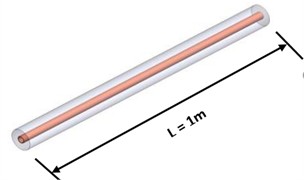
a) Case 1(smooth)
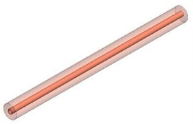
b) Case 2(Fully filled)
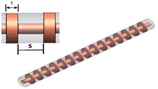
c) Case 3 (Circular-shaped baffles)
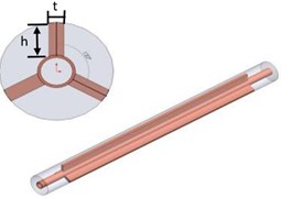
d) Case 4 (Cont.-3-1 fins)
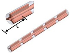
e) Case 5 (Int.-3-5 fins)
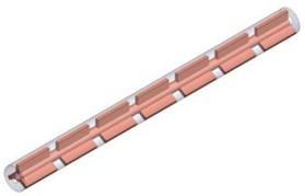
f) Case 6 (Int.-3-7 fins)
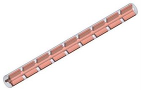
g) Case 7 (Int.-3-9 fins)
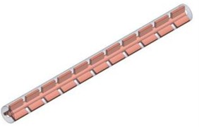
h) Case 8 (Int.-3-11 fins)
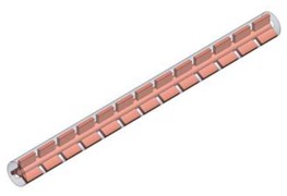
i) Case 9 (Int.-3-13 fins)
2.2. Governing equations and modeling assumptions
The flow problem for the incompressible and steady turbulent flow for both the fluid and porous phases in the DPHE was solved numerically. The governing equations (consisting of continuity, momentum, and energy equations) were solved by discretization using the SST - turbulence model, conjugate heat transfer analysis, and the Darcy-Forchheimer approach. The governing equation general form is illustrated below [22, 23].
Continuity equation:
Momentum Equation:
Energy equation:
where () is the velocity vector, () is the fluid density, () is the pressure, () is the temperature, ( is the specific heat, and () is the thermal conductivity.
For the case of copper foam materials, the governing equations for fluid flow and heat transport are given by the Forchheimer-Brinkman extension of Darcy's law using LTNE assumption. Hence, the equation that represents mass balance in 3D incompressible flow is written as [27]:
The porosity, (), is defined as the ratio of the connected void volume to the total volume of the porous medium:
For steady state and uniform flow density, the governing equation becomes the standard divergence-free condition for superficial velocity which is represented by ∇· = 0.
The volume averaged momentum equation for the porous copper is obtained based on the Forchheimer-Brinkman approach, which considers both the Darcy resistance term and Forchheimer inertial term. In addition to this, buoyancy effects are considered in the equation with the help of Boussinesq’s approximation [32]:
where (𝐾) is the permeability of the porous medium and () is the inertial loss coefficient. For open-cell copper foams, these quantities are correlated to the pore and fiber scales as:
The thermal behavior of the saturated porous region is described using an LTNE formulation. The energy equation for the fluid phase flowing through the foam can be expressed as [32]:
where and are the fluid and solid (foam matrix) temperatures, respectively; is the effective thermal conductivity of the fluid, is the specific interfacial area density between solid and fluid, and is the local interfacial heat-transfer coefficient.
The interfacial area density and local heat transfer coefficient were found by the following equations:
Dispersion thermal conductivity was found as follows:
Solid matrix:
The local convective heat transfer at the porous-fluid interface between the fluid in the fluid area and the edge of foam ligaments may be represented as follows:
where is solid thermal conductivity.
The Reynolds number employed in defining the flow regime is:
where represents the fluid density, denotes the hydraulic diameter signifies the characteristic velocity, and indicates the dynamic viscosity. The hydraulic diameter is determined by:
where is the cross-sectional flow area and is the wetted perimeter.
The current model considers the problem of resolving wall gradients while maintaining numerical stability in the free-stream zone. This model combines the advantages of the - turbulence model near the surface with the - turbulence model far from the walls, making it suitable for modeling enhanced heat transfer internal turbulent flows. Thermo-hydraulic behavior of the designs under study was analyzed based on three nondimensional criteria: Nusselt number (), friction factor (), and performance evaluation factor (PEF). These values were determined in accordance with the formulas provided in the literature [11]:
For carrying out the numerical calculation and maintaining a reasonable level of accuracy, the following assumptions were made:
– The flow is taken as steady, 3D, turbulent, and incompressible [22].
– The thermal properties of water were considered constant during all simulations.
– Heat transfer from the system to its surroundings was not considered by making the outer surface of the channel adiabatic.
– Complete thermal interaction was considered between the surfaces of the copper foam and the tube.
– Thermal non-equilibrium between the fluid and solid phases was also considered in the porous media.
3. Mesh independence
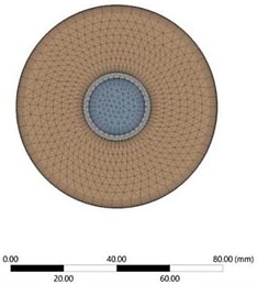
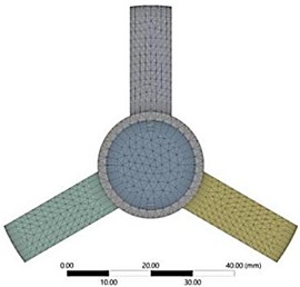
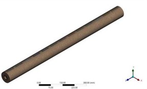
Unstructured tetrahedral elements were used to discretize the computational domain. Locally refinement meshes were applied near the solid-fluid boundaries and porous media to obtain accurate solutions of boundary layer formation, velocity gradient, and possible flow recirculation’s in such locations. The cross-section mesh configuration is shown in Fig. 2, with the zoomed-in view of the interrupted porous geometry comprising 13 axial cuts and the strips. Grid independence of the numerical solution was checked by varying the number of elements from 1.1×10⁶ to 7.2×10⁶ in order to calculate the average Nusselt number of the annulus outlet. This study is tabulated in Table 4. It can be seen from the results that the relative difference of the average Nusselt number decreases below 1.2 % when the number of elements exceeds 6.2×10⁶. Thus, a mesh having about 6.2×10⁶ elements is utilized for further calculations.
Fig. 2Mesh generation for the double-pipe heat exchanger
4. Boundary conditions
Table 5 presents the boundary conditions for all scenarios. The inlet mass flow was established at both tube inlets, with hot fluid entering the inner pipe at a constant flow rate of 3 L/min, while cool fluid entered the annulus at an inlet flow rate varying from 1 to 9 L/min. The input temperatures for the hot and cold sides were set at 75 °C and 30 °C, respectively, while the outlet boundaries were defined using a pressure-outlet boundary condition at zero-gauge pressure. All solid–fluid interfaces were coupled using conjugate heat transfer with a no-slip velocity boundary condition and perfect thermal contact. The external surface tube is considered insulated, rendering heat losses to the environment negligible.
Table 4Grid independence test (GIT) based on the average Nusselt number
Number of mesh elements | Percentage deviation (%) | |
487377 | 38.24 | – |
714446 | 38.36 | 0.003138 |
941515 | 38.48 | 0.0033 |
1367537 | 38.824 | 0.008939 |
1793559 | 39.169 | 0.008886 |
2729288 | 39.58 | 0.01035 |
3665017 | 40.01 | 0.01086 |
4600746 | 40.44 | 0.01074 |
5536476 | 40.87 | 0.01063 |
6844341 | 40.968 | 0.00239 |
Table 5Boundary conditions used in CFD simulations
Parameter | Hot water | Cold water |
Inlet )volumetric flow rate( | 3 L/min | 1, 3, 5, 7, 9 L/min |
Inlet temperature | 75 °C | 30 °C |
Outlet type | Pressure outlet | Pressure outlet |
Wall condition | – | Adiabatic outer wall |
Interface | Conjugate heat transfer | – |
Turbulence model | SST - | SST - |
Convergence criteria | 10⁻6 for continuity, momentum, energy | – |
4.1. Numerical setup
The numerical simulations were carried out at atmospheric pressure. To improve numerical stability and increase convergence rate, double precision calculation and six cores of parallel computing were used. Gravity was considered in the negative -direction to avoid any buoyancy effects. Energy equations were also enabled to couple the heat and flow fields. SST - turbulence model was chosen due to its high computational performance in dealing with near-wall flows and its ability to be used in mixed convection problems in double pipe heat exchangers. Local Thermal Non-Equilibrium (LTNE) approach was applied to the regions filled with copper foam, which allows treating the fluid and solid phases separately in order to provide a realistic description of heat transfer from the working fluid to the copper foam matrix. Porous media was modeled using additional momentum sink sources that represent viscous resistance and inertial loss of the foam, which are proportional to the reciprocal of permeability and friction factor, respectively. Additionally, the interfacial area density () and interfacial heat transfer coefficient () were taken into account in order to simulate the thermal interaction between solid and fluid phases. Local value of interfacial heat transfer coefficient () was provided using User Defined Function (UDF) that allows changing it depending on local flow velocity according to the correlation proposed in ANSYS Fluent Users Guide.
4.2. Validation
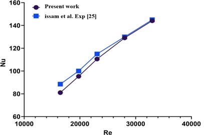
To verify the accuracy and predictive performance of the current numerical model, the latter was validated against experimental data obtained from Issam et al. [21]. As mentioned above, the geometry and thermo-hydraulic features of the experimental apparatus used in the reference work resemble the ones of the present work and therefore provide a basis for comparison with the predicted results. In terms of verification, the comparison between the experimentally measured and numerically calculated mean Nusselt number () and friction factor () at 16,300 < 32,500 for the baseline smooth pipe geometry was performed (as shown in Figs. 4-5). Good agreement was observed between the numerical calculations and experimental data in terms of both mean and . The difference in the values of the mean Nusselt number did not exceed ±5 %, while for the friction factor, this difference was limited to ± 7 % (respectively). Both discrepancies are acceptable for turbulent flows around wall-bounded surfaces. Other smaller discrepancies between the numerical data and experiments may occur because of the assumptions related to the turbulence-model coefficients used and the roughness of surfaces, diffusion numerical error, development of the inlet velocity profile, etc. Therefore, it is safe to conclude that the current numerical approach allows predicting adequately the flow and heat transfer properties of smooth DPHEs, which implies the use of such a numerical model for studying the inserts based on a copper foam.
Fig. 3Validation of the friction factor (f) outcome
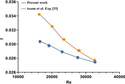
Fig. 4Validation of the average Nusselt number (Nu) results
5. Results and discussion
This section provides a detailed analysis of the numerical data for various design configurations of the DPHE. The discussion focuses on evaluating the impacts of geometric modifications, variations in flow rate, and the integration of porous media on overall thermos-hydraulic performance. Primary performance parameters, specifically the Nusselt number (Nu), the friction factor (), and the Performance Evaluation Factor (PEF), are calculated to evaluate the improvement in heat transfer in relation to the corresponding pressure drop penalty.
5.1. Influence of baffle geometry and arrangement on heat transfer
It is essential to establish the association between the volumetric flow rates and the corresponding Reynolds numbers advance of presenting the simulation results. This step enables a consistent interpretation of thermo-hydraulic response under different flow conditions. The relationship between various volumetric flow rates (1, 3, 5, 7, and 9 L/min) and a Reynolds number range of 205 to 1845 is clarified in Fig. 5. The linear correlation between flow velocity and fluid momentum, as can be seen from the numerical simulations, adequately maintained the boundary conditions. Furthermore, the thermophysical properties of water were nearly constant within the examined temperature range, as corroborated by this relationship.
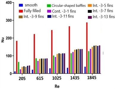
The effect of the Reynolds number () on the average Nusselt number () across the various configurations examined is illustrated in Fig. 6. The Nusselt number increases consistently with the Reynolds number, attributable to improvements in convective heat transfer resulting from increased flow rates and reduced boundary layer thickness. When the Reynolds numbers were 205 and 1845, the Nusselt number in the smooth DPHE rose from 12 to 38. Such a slight increase indicates the limited convection occurring without flow interference, where conductive heat transfer across the thermal boundary layer prevails. The use of metal foam significantly improved the coefficient of heat transfer within the DPHE. The fully filled foam model achieved the highest Nusselt number values, ranging from approximately 184 at low Reynolds numbers to nearly 291 at higher . This signifies approximately fifteen and eight times the enhancements, respectively, as compared to the smooth tube heat exchanger at the greatest and lowest Reynolds numbers. The observed improvement stems from the foam's substantial surface area and open pore structure, which facilitates fluid mixing and disrupts the boundary layer. Circular-shaped baffles exhibit lower Nusselt number values than the fully filled model, with values ranging from 65 to 126 at Reynolds numbers of 205 and 1845. Accordingly, the improvement of the Nusselt number or (heat transfer coefficient) was nearly five and three times greater, respectively, relative to the smooth tube. The continuous 3-1 fin and the interrupted foam 3-(5, 7, 9, 11, and 13) fins achieved the most balanced performance, with the int-3-13 fins model reaching a peak Nusselt number of approximately 158 at 1845. In contrast, the lowest Nusselt number of 23 was recorded in the continuous-3-1 fin at 205. Finally, the thermal performance of the DPHE was assessed in the subsequent sequence: filled, int-3-(13, 9, 11, 7, 5) fins, con-3-1 fin, circular baffles, and smooth tube. Among all configurations, the interrupted 3-13 fins yielded the highest Nusselt number, achieving approximately a 315 % and 275 % enhancement over the smooth tube at the high and low Reynolds numbers, respectively. The simulation data confirms that the design configuration plays a critical role in promoting local mixing and enhancing heat transfer. Furthermore, the frequency of interruptions directly influences the convective behavior. Augmenting foam sections typically improves recirculation and disrupts the boundary layer; However, severe obstruction may counteract these advantages. This study elucidates the suboptimal performance of the circular-shaped baffles, which, while generating significant disturbances, also create prolonged stagnant zones behind each baffle.
Fig. 5The relation between Reynolds number and volumetric flow rate for the cold-water
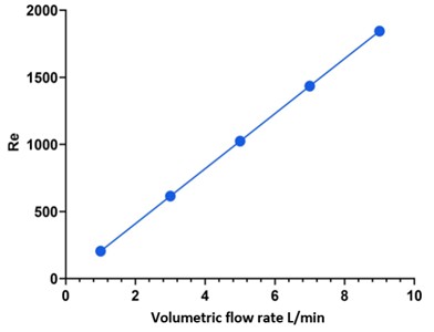
Fig. 6Variation of the average Nusselt number with Reynolds number for the investigated DPHE configurations
5.2. Influence of baffle geometry and arrangement on friction factor
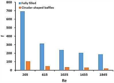
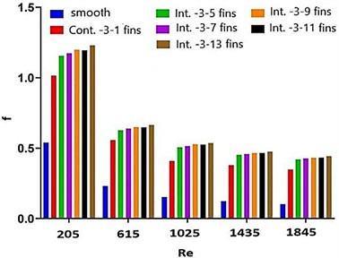
Given the extensive variation in pressure drop values observed throughout the examined configurations at the exact Reynolds numbers, Fig. 7 is divided into two segments (A and B) to facilitate more precise visualization and comparison of the results. Fig. 7(a) illustrates the relationship between the Reynolds number and the friction factor. In all examined configurations, including smooth tubes and int-3-(5,7,9,11,13) fins, the friction factor continuously declines monotonically with the Reynolds number as inertial forces increasingly overshadow viscous force effects. In the baseline heat exchanger construction with a smooth tube, the friction factor exhibited the lowest values across all evaluated configurations, decreasing from approximately 0.53 at 205 to about 0.10 at 1845.The observed trend indicates a streamlined and fully developed flow regime, in which viscous effects diminish progressively as the Reynolds number increases. In the interrupted foam configurations(int-3-5,7,9,11 and 13 fins), the friction factor was consistently low, varying from approximately 0.42 in the int-3-5 fins to about 0.44 in the int-3-13 fins at 1845.This behavior is attributed to the presence of gaps or cut regions, which reduce the continuous drag within the annulus and allow the flow to regain its momentum between successive foam blocks partially .Therefore, it ultimately resulted in a reduction in the friction factor of approximately 99.7 % relative to the fully packed configuration. In other words, the DPHE exhibits excellent hydraulic performance. The design accomplishes this decrease in flow resistance while still ensuring a significant enhancement in heat transmission. The optimal compromise between hydraulic performance and thermal enhancement was achieved using the axially interrupted 3-5 fins design. The completely filled foam arrangement has the greatest friction factor at the lowest Reynolds number, as illustrated in Fig. 7(b).The friction factor varies from approximately 693 at 205 to about 186 at 1845, indicating a nearly one order of magnitude increase relative to the circular shaped baffle arrangement inside the double-pipe heat exchanger .Similarly, the circular baffles exhibit an elevated friction factor, ranging from 104 at 205 to 18 at 1845,attributable to the partial occlusion of the flow stream .Additionally, the findings indicate that at the maximum Reynolds number examined (1845), the fully filled configuration exhibits a friction factor approximately 90.3 % higher than that of the circular baffles. Consequently, the significant increase underscores the substantial additional hydraulic resistance introduced when the porous region is completely saturated with metal foam.
Fig. 7Variation of friction factor with Reynolds number for the investigated foam configurations
a)
b)
5.3. Influence of baffle geometry and arrangement on performance evaluation factor (PEF)
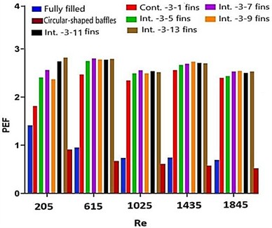
The performance evaluation factor (PEF) was adopted as the primary comparison metric among all simulation configurations. This dimensionless index accounts for both the enhancement in heat transfer and the additional pressure losses incurred by the foam structure, as commonly defined in the literature on porous media heat exchangers [22, 23]. Fig. 8 depicts the results of the baffle-foam configuration and arrangement's impact on the PEF inside the DPHE across various Reynolds numbers. The outcomes indicate that in the fully filled foam structure, a maximum PEF of 1.38 was achieved at 205, whereas circular-shaped baffles reached a value of 0.92. The data show that the fully filled foam worked about 33 % better than the circular-shaped baffles when the flow was low. Such superiority is mainly attributed to the extensive contact area and enhanced mixing inside the fully saturated porous region. With the Reynolds number increases, the PEF for both configurations consistently declines. The persistent decline occurs because the rate of increase in pressure drop exceeds the corresponding gain in heat transfer at higher flow velocities. Additionally, it is important to demonstrate that the interrupted fins foam configurations exhibit superior overall performance compared to the fully filled, circular-shaped baffles and the continuous 3-1 fins configuration. Across the Reynolds number range of 205-1845, the peak PEF value is 2.8 at 205 in the int.-3-13 fins, while the minimum PEF value is 2.4 at the lowest Reynolds number in the int.-3-5 fins. However, the PEF for the interrupted foam does not remain constant; instead, it initially increases at low Reynolds numbers and subsequently gradually decreases as the flow rate rises. This behavior reflects the competing physical mechanisms governing the thermo-hydraulic performance. In contrast, at low Reynolds numbers, the gaps(spacing)between foam-enhanced areas are irregular. Therefore, the recurrent regeneration of the boundary layer and increased mixing in these intervening zones significantly enhance convection while maintaining moderate pressure drops. The frictional resistance in the porous regions escalates more significantly with a rise in the Reynolds number. This is attributed to the amplification of inertial forces. Notwithstanding the continuous rise in heat-transfer coefficients, the PEF progressively diminishes in this domain as the hydraulic penalty begins to offset the thermal advantages. Finally, this trend suggests that interrupted metal-foam designs offer the optimal balance between heat-transfer enhancement and pressure drop cost at low to moderate Reynolds numbers. At the same time, their relative advantage diminishes under high-inertia flow conditions due to the disproportionately increasing drag. For the porous tube at 1500, the non-monotonic) rise-drop-rise (trend in TPF can be attributed to successive porous-flow regimes. At low velocities (Darcy regime), pressure losses scale nearly linearly with velocity, while heat transfer enhancement increases relatively faster, so TPF rises. With increasing velocity, inertial effects become important (Darcy-Forchheimer), causing a sharper growth in pressure drop/friction than in , so TPF drops. At higher flow intensity, incipient pore scale mixing/transitional effects can accelerate Nu again relative to the friction penalty, leading to a second rise in TPF [33-35].
Fig. 8Variation of the performance evaluation factor (PEF) with Reynolds number for the investigated DPHE configurations
5.4. Flow field and temperature distribution analysis
The significant thermal and hydraulic behaviors occurring in the double-pipe heat exchanger are shown under various design situations in Figs. 9-10. The simulation results of the temperature contours shown in Fig. 9 illustrate the thermal development along the flow direction for both the smooth tube (a), circular-shaped baffles (b), and the fully filled foam (c) configurations at a flow rate of 3 L/min. For the smooth tube, the temperature gradient was observed to be virtually linear and symmetric, suggesting a fully developed boundary layer with minimal thermal mixing. With the foam fully filled, the temperature gradient near the wall intensifies, and the isotherms become more compact, signifying enhanced heat transfer. This declines the outlet temperature by approximately 4-5 °C compared to the smooth channel. Conversely, the porous domains exhibit significantly non-homogeneous distributions of the local heat transfer coefficient in both the continuous (d) and interrupted fin topologies (e to i). In these configurations, the boundary layer is periodically refreshed with each reconnection, resulting in localized turbulence and increased convective mixing. This results in inhomogeneous but uniform temperature distributions, where foam portions and gaps (the spacing between fins) represent zones of elevated (hot) and lower (cold) temperatures, respectively. Consequently, the overall outcome is a 20-25 % increase in the wall-to-bulk flow temperature difference, consistent with the high Nusselt numbers explained previously.
Fig. 9Temperature distribution contours along the heat exchanger and the outlet section
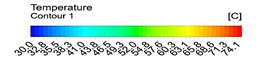

a) Smooth

b) Fully filled

c) Circular-shaped baffles
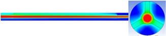
d) nt.-3-1 fins

e) Int.-3-5 fins
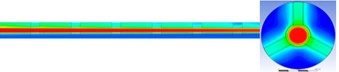
f) Int.-3-7 fins

g) Int.-3-13 fins
The mechanisms responsible for the observed thermal enhancement can be interpreted using the velocity contours shown in Fig. 10. In the smooth tube (a), the velocity profile remains nearly parabolic and fully developed, indicating a stable and symmetric flow field. However, the incorporation of porous regions (b-i) leads to a clear disruption of this symmetry. The existence of interrupted (e-i) foam blocks compels the fluid to accelerate around their edges, generating localized secondary flows and minor recirculation regions at the upstream and downstream interfaces of each portion. These flow disturbances intensify fluid mixing and repeatedly regenerate the thermal boundary layer, both of which contribute significantly to the enhancement of convective heat transfer. Although the formation of vortices increases flow resistance, leading to a higher friction factor, the thermal gains are much greater than the hydraulic penalties. This balance is reflected in the increased values of the performance evaluation factor (PEF) obtained for the interrupted designs.
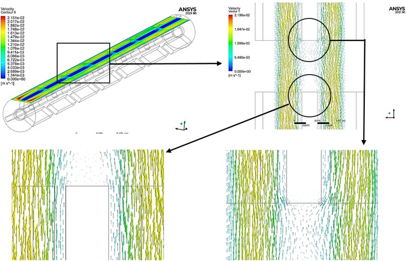
As shown in Fig. 11, the velocity-vector field in the vicinity of the interrupted foam inserts provides direct support for the proposed heat-transfer enhancement mechanism. When the flow approaches the leading edges of the foam segments, the local flow passage is constricted, resulting in a clear acceleration of the fluid through the adjacent open regions. The enlarged views further reveal low-velocity wake regions immediately downstream of the interrupted sections, together with local recirculating motion and vector deflection near the insert surfaces. These features indicate repeated flow separation and reattachment around the foam interruptions, which continuously disturb the developing hydrodynamic and thermal boundary layers.
This repeated interruption of the boundary layer promotes its regeneration along the flow direction and enhances fluid exchange between the near-wall region and the core flow. As a result, the interrupted configuration produces stronger local mixing and more effective renewal of the fluid adjacent to the heated surface, thereby improving convective heat transfer. Therefore, the thermal enhancement observed in the present design can be attributed not only to the presence of the porous insert itself, but also to the combined effects of local flow acceleration, wake formation, recirculation, and repeated boundary-layer disruption/regeneration evidenced by the velocity vectors.
Fig. 10Velocity contour
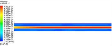
a) Smooth
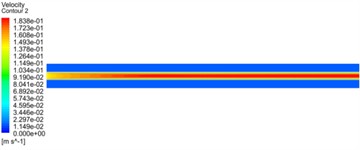
b) Fully filled
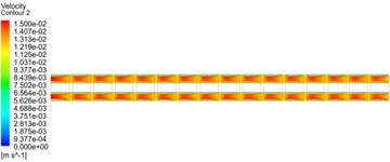
c) Circular-shaped baffles
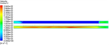
d) Cont.-3-1 fins
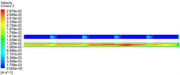
e) Int.-3-5 fins
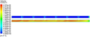
f) Int.-3-7 fins
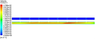
g) Int.-3-9 fins
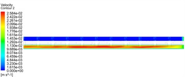
h) Int.-3-11 fins
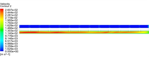
i) Int.-3-13 fins
5.5. Comparative performance assessment of DPHE
Fig. 12-13 demonstrate the comparative performance of the friction factor, Nusselt number, and performance evaluation factor (PEF) across various designs and flow rates. These characteristics indicate the simultaneous effect of design geometry and flow rate on the global thermo-hydraulic performance in DPHE. Fig. 12 shows a significant decrease in the friction factor as the water flow rate increases, indicating the rising dominance of inertial effects over viscous effects at greater Reynolds numbers. In all examined cases, the lowest thermal resistance is achieved at a flow rate of 5 L/min, while the highest resistance is observed at 1 L/min.
Fig. 11Velocity vectors around the interrupted foam inserts at 3 L/min, showing local recirculation and boundary-layer regeneration
This rise at lower flow rates is primarily attributed to the formation of a thicker thermal boundary layer, accompanied by an extended fluid residence time in the DPHE, subsequently prolonging the period of heat transfer. Also, the con.-3-1fin, and int.-3-(5,7,9,11,13) fins show greater friction factors than the reference case as a result of the additional blockage of flow. However, the slight increase in friction suggests a manageable hydraulic penalty, at least in the laminar-to-transition range.
Fig. 12Effect of water flow rate on the friction factor (1, 3 and 5 L/min)
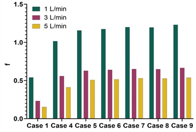
Fig. 13Effect of water flow rate on the Nusselt number (1, 3 and 5 L/min)
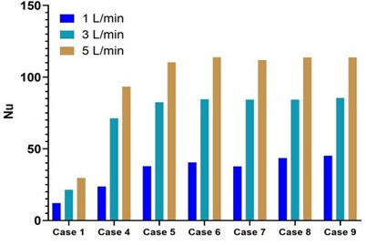
The impact of the volumetric flow rate on the Nusselt number in a DPHE with straight interrupted porous fins is shown in Fig. 13. The results indicated that the Nusselt number grows considerably as the flow rate rises for all configurations, due to enhanced convective mixing and increased wall heat transfer coefficients. The average Nu for the enhanced int.-3-(5,7,9,11,13) fins is approximately three to four times that of the plain tube (smooth DPHE) at a flow rate of 5 L/min. The porous channel, including int.-3-(9,13) fins, shows the most significant improvement of the Nusselt number, due to the repeated regeneration of the boundary layer and localized flow acceleration within the porous channels. Additionally, these configurations preserve a more pronounced temperature gradient between the wall and the fluid throughout the length of the exchanger.
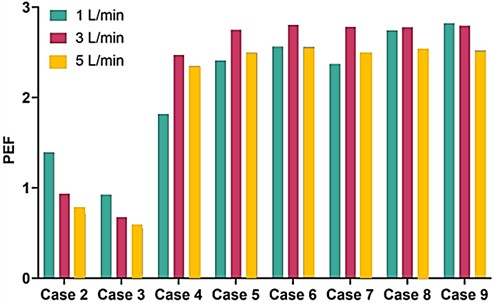
Fig. 14 shows the influence of flow rate on the thermal-hydraulic performance of all examined configurations with and without metal foam, as determined by the Performance Evaluation Factor. The results proves that the PEF declines with rising flow rate for fully filled and circular-shaped baffles in the DPHE (cases 2 and 3). The rationale for this decline is that the growing of the friction factor exceeds the improvement in heat transfer. Consequently, when the flow rate increases, the friction factor rises more rapidly, resulting in a significant decline in PEF. In contrast, for configurations using straight, interrupted foam fin geometries, the optimal PEF occurs at a flow rate of 3 L/min. As a result, an advantageous balance between heat transfer enhancement and pressure drop is achieved. The PEF peaks for int.-3-(7,13) fins, reaching around 2.8-2.77 at 3 L/min, indicating that the enhancement in heat transfer surpasses the pressure drop. Overall, int.-3-7 fins provide the most favorable balance between thermal performance and pressure across the considered range, achieving the optimum geometry.
Fig. 14Effect of flow rate on the performance evaluation factor (PEF) (1, 3 and 5 L/min)
The enhancement ratios obtained in the present study compare favorably with those reported in earlier investigations on metal-foam-enhanced DPHEs, although direct quantitative comparison should be treated cautiously because of differences in geometry, operating conditions, and performance definitions. In the current work, the fully filled foam configuration produced the highest thermal enhancement, with the average Nusselt number increasing by up to about 15 times relative to the smooth baseline, while the preferred interrupted configuration, Int.-3-7, provided the most favorable thermo-hydraulic balance. This level of improvement is higher than the Nusselt-number enhancement of about 117-146 % reported for customized copper-foam inserts by Zuhair et al. [22, 23], and also exceeds the 184 % enhancement reported by Nati et al. [24, 25] for perforated metal-foam topologies combined with CuO-water nanofluid. Moreover, the overall thermo-hydraulic behavior of the interrupted layouts in the present study is consistent with the experimental findings of Aljubury et al. [21], who reported Nusselt-number improvements of about 275-500 % over the clear tube for metal-foam twisted tapes, and with the PEC values reported by Nati et al. [24, 25], where the best perforated configuration reached about 2.14, compared with approximately 2.8 in the present work.
5.6. Correlation of TPF
A data-driven nonlinear model is formulated to represent the correlation between the PEF and Reynold’s number (), number of fins (), Nusselt’s number (), and friction factor () as in Eq. (24):
where , 1, 2, 3, 4 referred to the correlation model coefficients whereasrefers to the error term. The experimental readings are firstly splitted into two samples, namely training and testing. The training sample is selected to form 70 % of the entire data while the remaining 30 % is kept unseen by the model as testing sample. The cross validation process, with four folds, is used to shuffle the training and testing for each time of training model to enhance the reliability of the model. At each training time, the optimum st of coefficient are selected based on the Levenberg-Marquardt algorithm. The model accuracy is evaluated using the mean absolute error percentage. Table 6 presents the optimum set of the model’s coefficients and the percentage mean absolute error between the measured and predicted TPF values, where , refer to the measured and estimated values of PEF respectively. Using cross validation of four folds, it is shown that the model has successfully predicted the PEF in terms of Reynold’s number (), number of fins (), Nusselt’s number (), and friction factor (). The mean of the percentage error is very small which reflect the model accuracy.
Table 6Correlation model’s parameters
1.693 | –0.692 | –0.032 | 1.126 | 0.003 | 2.054 |
6. Conclusions
The present numerical investigation demonstrated that copper metal-foam inserts can substantially enhance the thermo-hydraulic performance of double-pipe heat exchangers compared with the smooth baseline configuration. Nine configurations were examined, including one smooth case, one fully filled foam layout, circular-shaped baffles, one continuous three-strip foam layout, and five interrupted three-strip foam layouts with 5, 7, 9, 11, and 13 axial cuts, all at a porosity of 0.9 and a pore density of 40 PPI. Based on the obtained results, the following conclusions can be drawn:
1) Metal-foam inserts significantly improved convective heat transfer relative to the smooth annulus. Among all tested cases, the fully filled foam configuration produced the highest heat-transfer enhancement, with the average Nusselt number increasing by up to about 15 times relative to the smooth heat exchanger, depending on Reynolds number. Although the fully filled foam yielded the maximum thermal enhancement, it also generated the largest hydraulic penalty. Therefore, it was not the most favorable option from an overall thermo-hydraulic standpoint.
2) Interrupted straight-fin foam arrangements provided a more balanced performance because they promoted boundary-layer redevelopment, local recirculation, and enhanced fluid mixing while avoiding the excessive flow resistance associated with the fully filled foam case.
3) For the interrupted configurations, the friction factor increased by approximately 1.5-3 times compared with the smooth tube, indicating a measurable hydraulic penalty. However, this penalty was offset by the associated gain in heat transfer, resulting in improved overall thermo-hydraulic behavior. Direct pressure-drop values and pumping-power requirements were not explicitly quantified in the present study and should be included in future practical design assessments.
4) The performance evaluation factor (PEF) showed that interrupted foam layouts outperformed the fully filled, circular-baffle, and continuous-strip configurations in terms of the balance between heat-transfer enhancement and pressure-drop cost. Within the investigated operating range, the most favorable overall performance was observed around a flow rate of 3 L/min, based primarily on the maximum PEF rather than on heat-duty or pumping-power analysis alone.
5) Among the interrupted configurations, the Int.-3-7 design emerged as the preferred layout because it provided the most favorable compromise between improved heat transfer and acceptable pressure loss, thereby delivering the best overall thermo-hydraulic performance under the tested conditions.
6) Overall, the results confirm that foam topology is a decisive parameter in determining the thermal and hydraulic response of the exchanger. Proper spatial interruption of porous inserts offers a practical route to enhance exchanger effectiveness while maintaining a reasonable hydraulic cost.
7) Overall, the results confirm that foam topology is a decisive parameter in determining the thermal and hydraulic response of the exchanger. Proper spatial interruption of porous inserts offers a practical route to enhance exchanger effectiveness while maintaining a reasonable hydraulic cost
8) The present conclusions were established for copper metal foam with a porosity of 0.9 and a pore density of 40 PPI. Therefore, although the observed thermo-hydraulic trends are useful for the investigated configurations, their direct extension to other porous structures, pore densities, or porosity levels should be made with caution until further numerical and experimental verification is performed.
9) The numerical reliability of the present CFD study was supported by a mesh-independence assessment, which showed negligible variation in the predicted Nusselt number beyond approximately 6.2×10⁶ elements, by the adopted convergence criterion of 10-6 for the governing equations, and by validation against published experimental data, with deviations within ±5 % for the average Nusselt number and ±7 % for the friction factor. A formal uncertainty analysis, however, was beyond the scope of the present study and should be considered in future work.
In addition, a nonlinear data-driven correlation was developed to predict the thermo-hydraulic performance factor (TPF) as a function of Reynolds number, number of fins, Nusselt number, and friction factor, as expressed by Eq. (24). The model was fitted using 70 % of the available data for training and 30 % for testing, with four-fold cross-validation, and its prediction performance was assessed using the percentage mean absolute error reported in the correlation section.
References
-
S. K. Singh, V. Khan, and R. Kacker, “Thermal performance optimization of double pipe heat exchanger using novel wire coil helical inserts,” International Communications in Heat and Mass Transfer, Vol. 162, p. 108624, Jan. 2025, https://doi.org/10.1016/j.icheatmasstransfer.2025.108624
-
S. A. Kadhim, O. A. A.-M. Ibrahim, M. K. S. Al-Ghezi, and A. M. Ashour, “Critical review of the use of TiO2 nanofluid as a heat transfer fluid in the double-pipe heat exchanger,” Journal of Thermal Analysis and Calorimetry, Vol. 150, No. 16, pp. 11995–12015, Jul. 2025, https://doi.org/10.1007/s10973-025-14531-y
-
M. Jafari, “An innovative tetramerous heat blade device for double pipe heat exchangers: an experimental study,” Applied Thermal Engineering, Vol. 257, p. 124414, Sep. 2024, https://doi.org/10.1016/j.applthermaleng.2024.124414
-
S. A. Kadhim et al., “Review of insertion scenarios in enhancement performance of double-pipe heat exchanger: case of cut twist tape,” Chemical Engineering and Processing – Process Intensification, Vol. 213, p. 110308, Apr. 2025, https://doi.org/10.1016/j.cep.2025.110308
-
S. A. Kadhim et al., “Increasing the thermal performance of double-pipe heat exchangers by active methods: a comprehensive review,” International Communications in Heat and Mass Transfer, Vol. 169, p. 109837, Oct. 2025, https://doi.org/10.1016/j.icheatmasstransfer.2025.109837
-
H. Ali Hadi, R. Ali Hussein, and A. A. Abbas Aljanabi, “Enhancement of heat transfer strategies in double pipe heat exchanger: a review,” The Iraqi Journal for Mechanical and Materials Engineering, Vol. 23, No. 2, pp. 14–41, Dec. 2024, https://doi.org/10.32852/xyhcd368
-
S. A. Kadhim et al., “Enhancing the thermal performance of double-pipe heat exchangers using wire coil inserts: a focused review,” Scientific African, Vol. 29, p. e02896, Aug. 2025, https://doi.org/10.1016/j.sciaf.2025.e02896
-
N. V. K., “Opportunities, challenges, and state of the art of flexible heat-pipe heat exchangers: a comprehensive review,” Heat Transfer, Vol. 53, No. 2, pp. 893–938, Mar. 2024, https://doi.org/10.1002/htj.22978
-
E. Tavousi, N. Perera, D. Flynn, and R. Hasan, “Heat transfer and fluid flow characteristics of the passive method in double tube heat exchangers: a critical review,” International Journal of Thermofluids, Vol. 17, p. 100282, Jan. 2023, https://doi.org/10.1016/j.ijft.2023.100282
-
H. Hamed, A. Mohammed, R. Khalefa, O. Habeeb, and M. Abdulqader, “The effect of using compound techniques (passive and active) on the double pipe heat exchanger performance,” Egyptian Journal of Chemistry, Mar. 2021, https://doi.org/10.21608/ejchem.2021.54450.3134
-
S. Bhattacharyya et al., “Thermal performance enhancement in heat exchangers using active and passive techniques: a detailed review,” Journal of Thermal Analysis and Calorimetry, Vol. 147, No. 17, pp. 9229–9281, Feb. 2022, https://doi.org/10.1007/s10973-021-11168-5
-
R. Andrzejczyk, T. Muszynski, and P. Kozak, “Experimental and computational fluid dynamics studies on straight and U-bend double tube heat exchangers with active and passive enhancement methods,” Heat Transfer Engineering, Vol. 42, No. 3-4, pp. 167–180, Feb. 2021, https://doi.org/10.1080/01457632.2019.1699279
-
A. Alhusseny, A. Turan, and A. Nasser, “Rotating metal foam structures for performance enhancement of double-pipe heat exchangers,” International Journal of Heat and Mass Transfer, Vol. 105, pp. 124–139, Sep. 2016, https://doi.org/10.1016/j.ijheatmasstransfer.2016.09.055
-
R. M. K. Ali and S. Lafta Ghashim, “Numerical analysis of the heat transfer enhancement by using metal foam,” Case Studies in Thermal Engineering, Vol. 49, p. 103336, Jul. 2023, https://doi.org/10.1016/j.csite.2023.103336
-
L. Shen, S. Xu, Z. Bai, Y. Wang, and J. Xie, “Experimental study on thermal and flow characteristics of metal foam heat pipe radiator,” International Journal of Thermal Sciences, Vol. 159, p. 106572, Aug. 2020, https://doi.org/10.1016/j.ijthermalsci.2020.106572
-
K. Chen, X. Wang, P. Chen, and L. Wen, “Numerical simulation study on heat transfer enhancement of a heat exchanger wrapped with metal foam,” Energy Reports, Vol. 8, pp. 103–110, Jan. 2022, https://doi.org/10.1016/j.egyr.2022.01.147
-
P. H. Jadhav, N. Gnanasekaran, D. A. Perumal, and M. Mobedi, “Performance evaluation of partially filled high porosity metal foam configurations in a pipe,” Applied Thermal Engineering, Vol. 194, p. 117081, May 2021, https://doi.org/10.1016/j.applthermaleng.2021.117081
-
T. S. Athith, G. Trilok, P. H. Jadhav, and N. Gnanasekaran, “Heat transfer optimization using genetic algorithm and artificial neural network in a heat exchanger with partially filled different high porosity metal foam,” Materials Today: Proceedings, Vol. 51, pp. 1642–1648, Dec. 2021, https://doi.org/10.1016/j.matpr.2021.11.248
-
A. Sheikhi Azizi, M. Razbin, S. M. Mousavi, M. Li, and A. A. Rabienataj Darzi, “Enhancing thermal efficiency in twisted tri-lobe double pipe heat exchangers via integrated CFD and AI approaches,” International Journal of Thermal Sciences, Vol. 206, p. 109331, Aug. 2024, https://doi.org/10.1016/j.ijthermalsci.2024.109331
-
Y. Zhang, M. Hangi, X. Wang, and A. Rahbari, “A comparative evaluation of double-pipe heat exchangers with enhanced mixing,” Applied Thermal Engineering, Vol. 230, p. 120793, May 2023, https://doi.org/10.1016/j.applthermaleng.2023.120793
-
I. M. A. Aljubury, R. G. Saihood, and A. A. Farhan, “Experimental study on thermo-hydraulic performance of metal foam twisted tape in a double pipe heat exchanger,” Heat Transfer, Vol. 51, No. 8, pp. 7910–7928, Dec. 2022, https://doi.org/10.1002/htj.22673
-
Z. S. Rabeeah, “Studying the influence of using metal foam baffles on the performance of double-pipe heat exchanger,” Journal of Thermal Engineering, Vol. 11, No. 1, pp. 196–214, Jan. 2025, https://doi.org/10.14744/thermal.0000913
-
Z. S. Faal, A. J. Jubear, and H. R. Al-Bugharbee, “A numerical investigation of the thermal performance of a double pipe heat exchanger with copper foam baffles,” International Journal of Renewable Energy Research, Vol. 15, No. 3, pp. 462–472, Sep. 2025, https://doi.org/10.20508/ijrer.v15i3.14870.g9099
-
M. B. Nati, A. J. J. Al-Jassani, M. G. Al-Azawy, and A. G. Nasser, “Numerical study of heat transfer on using metal foam and nanofluid in double pipe heat exchanger,” CFD Letters, Vol. 18, No. 3, pp. 152–172, Jul. 2025, https://doi.org/10.37934/cfdl.18.3.152172
-
M. Baqer, Abbas J. Jubear Al-Jassani, Mohammed Ghalib Al-Azawy, and Adel G. Nasser, “Thermal performance assessment of a double-pipe heat exchanger utilizing metal foam and nanofluids,” Wasit Journal of Engineering Sciences, Vol. 13, No. 3, pp. 13–24, Sep. 2025, https://doi.org/10.31185/wjes.vol13.iss3.668
-
X. Zhu, X. Jing, and L. Cheng, “Magnetorheological fluid dampers: A review on structure design and analysis,” Journal of Intelligent Material Systems and Structures, Vol. 23, No. 8, pp. 839–873, Mar. 2012, https://doi.org/10.1177/1045389x12436735
-
A. Jamarani, M. Maerefat, N. F. Jouybari, and M. E. Nimvari, “Thermal performance evaluation of a double-tube heat exchanger partially filled with porous media under turbulent flow regime,” Transport in Porous Media, Vol. 120, No. 3, pp. 449–471, Oct. 2017, https://doi.org/10.1007/s11242-017-0933-x
-
A. A. Dhavale and M. M. Lele, “Enhancing thermal-hydraulic performance in heat exchangers with metal foam inserts: A comprehensive experimental investigation,” Experimental Heat Transfer, Vol. 38, No. 6, pp. 540–591, Sep. 2025, https://doi.org/10.1080/08916152.2024.2382806
-
F. Rizzo et al., “Construction and dynamic identification of aeroelastic test models for flexible roofs,” Archives of Civil and Mechanical Engineering, Vol. 23, No. 1, p. 16, Oct. 2022, https://doi.org/10.1007/s43452-022-00545-y
-
D. Ribeiro, R. Calçada, J. Ferreira, and T. Martins, “Non-contact measurement of the dynamic displacement of railway bridges using an advanced video-based system,” Engineering Structures, Vol. 75, pp. 164–180, Jun. 2014, https://doi.org/10.1016/j.engstruct.2014.04.051
-
X. Chen and A. Kareem, “Advances in modeling of aerodynamic forces on bridge decks,” Journal of Engineering Mechanics, Vol. 128, No. 11, pp. 1193–1205, Oct. 2002, https://doi.org/10.1061/(asce)0733-9399(2002)128:11(1193)
-
T. Fiedler, R. Moore, and N. Movahedi, “Manufacturing and characterization of tube-filled ZA27 metal foam heat exchangers,” Metals, Vol. 11, No. 8, p. 1277, Aug. 2021, https://doi.org/10.3390/met11081277
-
S. Bu, Z. Yang, W. Zhang, H. Liu, and H. Sun, “Research on the thermal performance of matrix cooling channel with response surface methodology,” Applied Thermal Engineering, Vol. 109, pp. 75–86, Aug. 2016, https://doi.org/10.1016/j.applthermaleng.2016.08.005
-
S. Liu et al., “From Rayleigh-Bénard convection to porous-media convection: How porosity affects heat transfer and flow structure,” Journal of Fluid Mechanics, Vol. 895, p. A18, Jul. 2020, https://doi.org/10.1017/jfm.2020.309
-
M. Aghaei-Jouybari, J.-H. Seo, S. Pinto, L. Cattafesta, C. Meneveau, and R. Mittal, “Extended Darcy-Forchheimer law including inertial flow deflection effects,” Journal of Fluid Mechanics, Vol. 980, p. A13, Feb. 2024, https://doi.org/10.1017/jfm.2023.1083
About this article

The authors have not disclosed any funding.
The datasets generated during and/or analyzed during the current study are available from the corresponding author on reasonable request.
Inas Faiz Kadhium: investigation, resources, CFD simulation, data curation, visualization, and original draft preparation. Abbas J. Jubear Al-Jassani: conceptualization, methodology, supervision, validation, formal analysis, review, and editing. Hussein Razzaq Al-Bugharbee: conceptualization, methodology, supervision, validation, formal analysis, review, and editing.
The authors declare that they have no conflict of interest.