Abstract
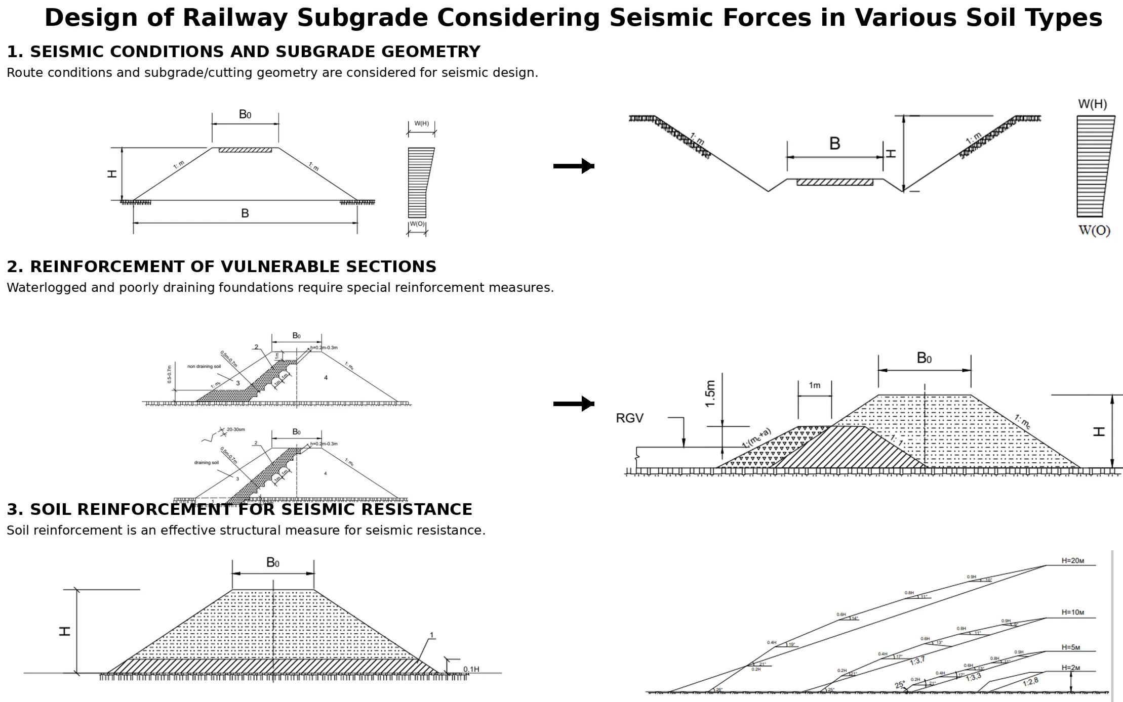
The article addresses the issues of railway design in seismic regions, taking into account the specific behavior of foundation soils and the topographical characteristics of the terrain. Based on the obtained results and the briefly described experimental methodologies, recommendations are provided for selecting structural solutions suitable for seismic areas. In addition, new structural designs have been developed that combine reliability under seismic loading with efficient use of construction materials. The proposed theoretical solutions have been refined and validated through experimental investigations.
Highlights
- Railway subgrade design in seismic regions considers foundation soil and terrain conditions.
- Experimental and theoretical studies support the selection of reliable structural solutions for seismic areas.
- Proposed designs improve seismic resistance while ensuring efficient use of construction materials.
1. Introduction
To ensure the seismic stability of railway subgrades, it is essential to select the route alignment properly, that is, in a manner advantageous from a seismic standpoint. The design seismic intensity of individual sections of the route depends significantly on the conditions under which the railway is laid. It is well known that within a single seismic zone, the design seismic intensity varies depending on the geological, hydrogeological, and topographical characteristics of the area. Therefore, it is crucial to obtain at least approximate data on the parameters influencing the initial seismicity of the region through which the railway passes.
An analysis of empirical data obtained from post-earthquake damage assessments [1-3] indicates that the intensity of earthquake manifestations depends on the engineering-geological, hydrogeological, and geomorphological structure of the terrain.
2. Related work
For technical and economic reasons, seismic microzonation is advisable in the design of railway subgrades due to the considerable longitudinal extent of such structures. For extended linear infrastructure, the most rational method for assessing the initial seismic intensity of a given area is the analogy method [4]. This approach involves comparing soil conditions, terrain characteristics, and other relevant factors with those of sites for which the initial seismic intensity values have already been established.
It is well recognized that the proper design of the railway subgrade and the technology employed in its construction largely determine the durability of the costly pavement structure and track superstructure under normal operating conditions. Under seismic conditions, however, the importance of the subgrade is significantly amplified, and the design requirements become substantially more stringent.
With modern construction mechanization – particularly in the conditions of the Central Asian republics and Uzbekistan – the subgrade accounts for a relatively small portion of the total estimated construction cost (approximately 5-15 %). This provides the opportunity to modify its structural configuration in consideration of seismic effects without significantly increasing overall project costs.
For the development of effective structural solutions, it is advisable to analyze subgrade performance across different sections of the railway alignment [5, 6, 13].
High-speed rail transportation offers important benefits to consumers and society: safety, high carrying capacity, and environmental friendliness. It is a tool for political integration, provides connections between regions, stimulates the modernization of other types of transport, and significantly increases people’s mobility [16].
Scientific novelty of the study. Unlike conventional approaches that primarily focus on seismic hazard assessment or general railway subgrade design, the present study integrates seismic microzonation principles with engineering-geological, hydrogeological, and geomorphological characteristics to develop a more reliable framework for railway subgrade design in earthquake-prone regions. The proposed approach emphasizes the application of the analogy method for long linear infrastructure while considering the influence of varying local ground conditions on design seismic intensity. Furthermore, the study provides practical structural recommendations that enable the optimization of railway subgrade configurations under seismic loading with minimal additional construction costs, thereby improving the safety, resilience, and long-term performance of railway infrastructure in seismically active areas.
3. Materials and methods
In the course of numerous studies, the coefficient of dynamic stability, , was established. Its value is determined as the ratio of the acceleration at the upper points of the subgrade slopes, , to the acceleration at the lower points, :
When the obtained value of is exceeded, failure of the cut and embankment slopes of the railway subgrade occurs, leading to damage of the track superstructure and the pavement structure.
The application of the established value of this coefficient makes it possible to select an optimal subgrade design capable of resisting seismic effects during experimental studies without bringing the structure to a failure state. This approach is of particular practical significance in experimental investigations conducted on existing and newly constructed railways.
Furthermore, the use of this coefficient as a governing parameter results in substantial savings – up to 50-60 % – in both experimental time and construction material consumption.
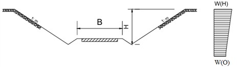
Fig. 1Influence of the subgrade structure on the increase in design seismic intensity
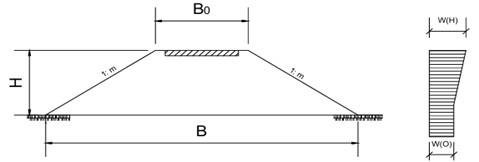
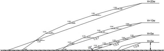
The experimental results allow the following formula [8] to be recommended for determining the slope inclinations of the railway subgrade, taking into account the seismicity of the region. The figure is taken from the work of Abdujabarov A.Kh., who is also a co-author of this manuscript:
where – the slope inclination coefficient of the railway subgrade in non-seismic regions (1.5); – slope inclination coefficient of the railway subgrade in non-seismic regions (1.5); – coefficient of relative compaction of the embankment soil (expressed as a fraction of the standard); – width of the subgrade at the top, in meters; 12 m; – coefficient depending on the seismicity of the railway section; equal to 0.1, 0.2, and 0.4, respectively, for a design seismic intensity of 7, 8, and 9 points. (according to SNiP II-7-81); – coefficient accounting for allowable road damage (0.25); – height of the subgrade, in meters; up to 6 meters; – dynamic characteristic coefficient of the subgrade soil (based on experimental results: clay – 12, loam – 20, sandy loam – 30, gravel and crushed stone – 40, coarse sand – 50, medium sand – 60, fine sand (dune sand) – 70).
When designing cuttings in the railway subgrade, it is recommended to determine the slope steepness of the cutting using the following formula:
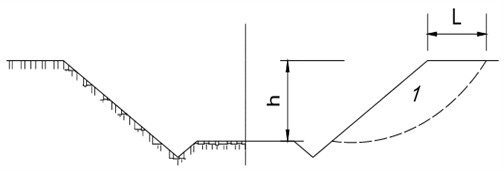
where is the width of the active soil zone (Fig. 2) (for sandy soils: 2 h; for cohesive soils: 3 h); – depth of the cutting; up to 12 m; the remaining notations are taken from Eq. (2).
Sections of temporarily waterlogged embankments of railway subgrades are particularly vulnerable to earthquakes. Although such sections are designed relatively rarely, earthquake aftermath analyses have shown that even moderate tremors (6-7 on the intensity scale) can cause severe damage, rendering them unsuitable for further operation.
4. Results and discussion
Analysis of damage to such sections of railway embankments revealed that, during the design of the transverse profile, measures to ensure seismic resistance are typically not incorporated. In other words, these sections are designed for seismic regions in the same manner as for normal, non-seismic conditions.
Fig. 2Schematic diagram for the calculation of a railway subgrade cutting
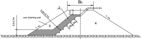
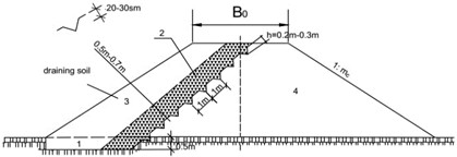
Experimental results and analyses of earthquake consequences have shown that sections with temporarily waterlogged soil foundations require special attention. In the absence of such soils, additional reinforcement must be provided: for clayey subgrade soils, see Fig. 3(a); for sandy soils, see Fig. 3(b).
During the reconstruction of railways involving subgrade widening, the traditional method of loosening the slope and filling the extended portion of the embankment does not ensure the monolithic integrity of the entire subgrade. This often leads to wide longitudinal cracks of up to 30 cm under seismic loading. Studies have demonstrated that, on slopes of existing embankments composed of cohesive soils, it is advisable to cut triangular-shaped trenches 20-30 cm deep and subsequently fill them with a layer of coarse gravel. The distance between trenches should be 1 m, and the soil between trenches on the slope toward which the subgrade is being widened should not be loosened.
Fig. 3Reinforcement of a Waterlogged Railway Embankment: a) cohesive subgrade soils; b) draining subgrade soils. The coefficient a= 0.25 for seismic intensity J= 7, a= 0.5 for J= 8, and a= 0.75 for J= 9. The figure is taken from the work of Abdujabarov A.Kh., who is also a co-author of this manuscript
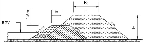
For non-draining or poorly draining soils, a transverse profile of the embankment widened for a second track is recommended according to Fig. 3(a), while for draining soils, the profile shown in Fig. 3(b) should be used.
The most vulnerable subgrade embankments, under both earthquakes and industrial explosions, are those passing through swampy areas. Although such waterlogged sections are relatively rare, they are often unavoidable when crossing riverbeds, even in mountainous regions. SNiP II-7-81 does not address the specific design features of subgrades in these areas, nor in many other seismically vulnerable sections of railway alignments [8].
Fig. 4Transverse profile of the embankment widened for a second track: 1 – soil cutting zone; 2 – coarse gravel fill; 3 – backfill soil; 4 – existing embankment
a)
b)
Soil reinforcement of the railway subgrade is the most effective structural measure for ensuring its seismic resistance [8].
A variant of reinforced soil is the use of soil-concrete layers with a thickness of 10-15 cm, spaced vertically at 1.0 m for sandy soils and 1.5-2.0 m for cohesive soils. This structural measure allows a reduction of the design slope steepness of the embankment by 0.5. Economically, such a measure is effective only in non-aggressive environments, as the strength of soil-concrete layers in aggressive conditions decreases sharply over time.
For seismic regions, the optimal composition is a mixture containing 5-10 % cement by the mass of dry soil, depending on the density and strength of the soil being reinforced [13].
It should be noted that regulatory documents on the seismic resistance of road structures, both domestically and internationally, do not cover recent engineering solutions in this field and require further specification. Moreover, these regulations do not even address major roadway structures comprehensively, focusing primarily on the subgrade. Expensive pavement layers and track superstructures are designed in the same manner for both seismic and non-seismic regions.
Fig. 5Railway Subgrade Designs in Rock Soils: 1 – Seismic isolation layer. The figure is taken from the work of Abdujabarov A. Kh., who is also a co-author of this manuscript
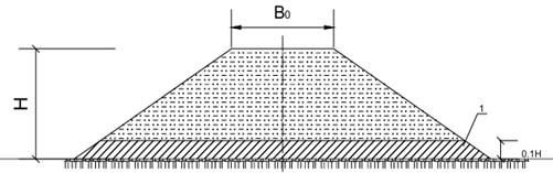
Fig. 6Comparison of Slope Calculation Results Using the Method of Sh. G. Napetvaridze and Eq. (2). The figure is taken from the work of Abdujabarov A. Kh., who is also a co-author of this manuscript
5. Conclusions
Taking seismic forces into account when selecting soil foundations can significantly reduce the design seismic intensity and help avoid hazardous sections. Increasing the slope gentleness of the railway subgrade, depending on the magnitude of the design seismic intensity, can ensure the overall stability of the roadway.
Reinforcement of subgrade slopes or soil reinforcement is an effective structural solution for ensuring seismic resistance, but it should be implemented based on technical and economic assessments.
References
-
A. Abdujabarov, M. Mekhmonov, P. Begmatov, F. Eshonov, and M. Khamidov, “Consideration of the environmental impact on the seismic inertial forces of the railway track in difficult conditions,” in AIP Conference Proceedings, Vol. 3045, No. 1, p. 030097, Mar. 2024, https://doi.org/10.1063/5.0197332
-
A. Abdujabarov, F. Eshonov, P. Begmatov, M. Mekhmonov, and M. Khamidov, “Calculation of the seismic stress state of the ground-gallery system,” in AIP Conference Proceedings, Vol. 3045, No. 1, p. 030098, Mar. 2024, https://doi.org/10.1063/5.0197333
-
T. B. Imanaliev, Seismic Resistance of Avalanche Protection Galleries. Bishkek: KSUCTA, 2005, p. 147.
-
G. M. Stoyanovich, V. V. Pupatenko, and K. V. Zmeev, “Ensuring track stability in the transition zone between artificial structures and subgrade,” Track and Track Economy, No. 10, pp. 14–17, 2017.
-
V. V. Kosmin, “Prospects for the construction of railways and highways in Russia,” Transport Construction, No. 1, pp. 4–6, 2008.
-
T. B. Imanaliev, “Selection of protective gallery designs based on geological conditions,” Science and New Technologies, No. 1, pp. 28–33, 2011.
-
S. A. Kudryavtsev, V. V. Pupatenko, and E. S. Danilyants, “Prediction of residual deformation accumulation in railway subgrades under train impact,” World of Transport, No. 2, pp. 136–142, 2008.
-
E. S. Danilyants and V. V. Pupatenko, “Influence of vibrodynamic train impact on deformability and strength of railway subgrades,” in Proceedings of the 5th International Scientific Conference “Scientific, Technical and Economic Cooperation of Asia-Pacific Countries in the 21st Century, pp. 41–44, 2007.
-
V. I. Gritsyk and M. V. Okost, “Railway subgrade for high loads and high-speed traffic,” Track and Track Economy, No. 8, pp. 36–38, 2008.
-
G. G. Konshin, “Vibration method for diagnosing embankments,” Track and Track Economy, No. 10, pp. 22–25, 2007.
-
A. N. Kostousov, “Reinforcement,” World of Transport, No. 5, pp. 170–175, 2011.
-
M. K. Makhmonov, P. A. Begmatov, and A. K. Mavlanov, “Stability calculations of road embankments reducing risks in seismically active areas,” Transport Construction, No. 3, pp. 53–58, 2024.
-
A. K. Abduzhabarov, P. A. Begmatov, and M. K. Kenzhaliev, “Calculation of railway subgrade considering high-speed train traffic,” E3S Web of Conferences, Vol. 531, No. 1, p. 02006, 2024, https://doi.org/10.1051/e3sconf/202453102006
-
K. S. Lesov and M. K. Kenjaliyev, “Organizational and technological parameters during the construction of the Bukhara-Misken railway line,” in AIP Conference Proceedings, Vol. 2471, p. 030026, Jun. 2022, https://doi.org/10.1063/5.0089621
-
M. Muzaffarova and M. Mirakhmedov, “Dilatation of the method of fixation moveable sands,” in AIP Conference Proceedings, Vol. 2612, p. 040007, 2023, https://doi.org/10.1063/5.0135327
-
P. Begmatov, J. Yuldashaliyev, and S. O. Umaraliev, “Strengthening of railroad track bed slopes during high-speed train traffic,” in AIP Conference Proceedings, Vol. 3447, p. 030006, May 2026, https://doi.org/10.1063/12.0044029
-
P. A. Begmatov, S. A. Tajibayev, J. B. Yuldashaliyev, F. F. Eshonov, and S. M. Umaraliyev, “Ensuring the stability of railway subgrade using geotextile materials on high-speed rail sections,” Vibroengineering Procedia, Vol. 62, pp. 168–175, Jun. 2026, https://doi.org/10.21595/vp.2026.26107
About this article

The authors have not disclosed any funding.
The datasets generated during and/or analyzed during the current study are available from the corresponding author on reasonable request.
The authors declare that they have no conflict of interest.

