Abstract
In order to improve ride comfort, mounting system was required to effectively isolate the vibrations generated by the engine, preventing them from being transmitted to the vehicle body and the cabin, while ensuring that the displacement of the powertrain remains within controllable limits under various operating conditions. This study investigated the vibration isolation performance of single bell plate hydraulic mount in a quarter‑car model. Key parameters including force transmissibility and relative displacement transmissibility were analyzed under varying damping of the main rubber spring, different mass combinations (engine, body, wheel) and different road excitations. The results showed that with optimized parameters (3.39×10⁴ N/m, 2500 N·s/m, 2.5×10⁵ N/m, 100 N·s/m), minimum force transmissibility in the low‑frequency region and low relative‑displacement transmissibility in the high‑frequency region can be achieved. Appropriate matching of , , and further reduced both force and relative‑displacement transmissibility. Under random road excitation, force transmissibility, mount stroke, and suspension stroke increased with road roughness, whereas relative displacement transmissibility between engine and frame decreased significantly (by 67.0 % on Grade B and 85.5 % on Grade C compared to Grade A). With impact excitation, force transmissibility changed variably with grade, while mount and suspension displacements were markedly amplified; nevertheless, the mount maintained effective control across all roughness levels.
1. Introduction
Hydraulic mounts, which are vibration-isolating elements installed between the vehicle body and the engine, have garnered significant attention from academia and the automotive industry, leading to extensive research in recent years [1-3]. These adaptive mounts are developed as smart isolators, designed to function as soft isolators at low amplitudes and stiff isolators at high amplitudes. This dual behavior places hydraulic engine mounts within the domain of nonlinear systems, resulting in phenomena not observed in linear analyses. The mounts must be soft to reduce transmitted forces and stiff to limit relative displacement. Based on the mount system, mounts can be broadly classified into three categories: passive mounts, semi-active mounts, and active mounts. These categories play a vital role in enhancing the Noise, Vibration, and Harshness (NVH) characteristics of the vehicle. Compared to rubber mounts, hydraulic mounts exhibit higher stiffness and damping at low frequencies, while displaying lower dynamic stiffness and damping at high frequencies. This dual behavior significantly improves both comfort and vibration noise reduction. Specifically, hydraulic mounts reduce noise levels by 5 dB compared to rubber mounts and decrease shock vibration levels by two-thirds. Current approaches to semi-active mounts involve controlling either structural parameters or fluid parameters [4]. Controllable structural parameters include the cross-sectional area of the inertial channel, the length of the inertial channel, and the variable volume stiffness of the upper and lower cavities. Controllable fluid parameters encompass smart materials, such as magnetorheological fluids and electrorheological fluids. In contrast, active mounts utilize an electric controller to send command signals to the active actuator, which then generates a reaction force to minimize the transmitted force.
From the perspective of vibration isolation performance, hydraulic mounts can be classified into three types: (1) single throttle hole or single inertial channel hydraulic mounts, (2) inertial channel combined with a decoupled film hydraulic mount (referred to as decoupled film hydraulic mount), and (3) inertial channel combined with both decoupled film and bell plate hydraulic mounts. Although the single throttle hole or single inertial channel hydraulic mount exhibits superior vibration isolation performance compared to rubber mounts in the low-frequency range, as the excitation frequency increases, the fluid in the inertial channel or throttling hole tends to stagnate, losing its vibration isolation effectiveness and even resulting in a state of diminished damping-commonly referred to as high-frequency stiffening [5]. The decoupled film hydraulic damping mount addresses this issue by incorporating a decoupled film based on the inertial channel hydraulic mount, which provides lower damping characteristics under high-frequency, low-amplitude excitations. While this mitigates the high-frequency stiffening problem to some extent, the issue remains significant. R Tikani et al. [6] investigated the efficiency of the proposed hydraulic engine mount in two-mode operation meaning isolating mode in the highway driving condition and damping mode in the shock motions. Fan R. et al. [7] studied a unique semiactive HEM with four-chamber and three-fluid-channel whose lengths shorten successively while the cross-sectional areas increase successively, which can offer good NVH performance in a relatively wider band. Ohadi et al. [8] developed a mathematical model for a six-degree-of-freedom, four-cylinder V-shaped engine mount, accounting for the nonlinearity of the decoupling film. They analyzed the impact of the throttle disc structure on the vibration isolation performance of the mount system.
Despite the relatively mature research on conventional inertial channel and decoupled film hydraulic mounts, studies on bell-plate hydraulic mounts remain limited. The bell plate hydraulic damping mount is an improvement upon the decoupling film hydraulic mount, incorporating a bell-plate structure to divide the upper liquid chamber into two separate cavities. By utilizing the bell-plate structure to disturb the fluid flow in the upper liquid chamber, it increases turbulent energy dissipation, thereby further mitigating the high-frequency hardening issue of hydraulic mounts [9-12]. In particular, there is a lack of systematic investigation into how the number of bell-plate structures affects the dynamic characteristics (e.g., dynamic stiffness and hysteresis angle) of hydraulic mounts. Lin et al. [13-16] proposed a novel bell plate hydraulic mount design that integrated an inertial channel, a decoupler membrane, and two bell plates to enhance broad-spectrum engine vibration isolation. Increasing the number of high-frequency bell plates from 0 to 2 resulted in a 69.88 % reduction in the peak dynamic stiffness of the hydraulic mount and a 37.71 % decrease in the hysteresis angle. Furthermore, although the synergistic effect between bell-plate disturbances and the decoupler membrane has been acknowledged, quantitative relationships and design guidelines regarding multiple bell plates are still absent. The studies on bell plate hydraulic mounts are limited, with few reports on the influence of the number of bell-plate structures on the dynamic characteristics of hydraulic mounts. In line with my earlier work (Jian Wei, 2026), the current analysis confirms that the disruptive effects of bell plate disturbances and the decoupler membrane synergistically mitigate the high-frequency hardening phenomenon encountered in hydraulic mounts at higher frequencies [17]. Additionally, a new bell plate controllable multi-inertia channel MRF (magnetorheological fluid) mount system was applied to a 3-degree-of-freedom mount system of a 1/4 car model. The study showed that switching and closing different inertia channels reduced the transfer force from the engine to the body and increased the relative displacement stiffness between the engine and the body. The application of bell-plate-based controllable multi-inertia channel MRF mount systems in vehicle-level models also remains underexplored.
To address the above gaps, this study makes the following specific contributions:
(1) Quantitative analysis of the number of bell plates: This study systematically investigates the influence of single bell plates, providing the first quantitative evidence of the effectiveness of bell plates.
(2) Synergistic mechanism of bell plates and decoupler membrane: Building upon prior work (Jian Wei, 2026), this study confirms that the combined disruptive effects of bell-plate-induced turbulence and the decoupler membrane synergistically mitigate the high-frequency hardening phenomenon, offering a clearer physical explanation of the underlying mechanism.
(3) Application to a quarter-car model: Single bell-plate mount system is applied to a 3-degree-of-freedom quarter-car model. The study demonstrates that bell-plate disturbances and the decoupler membrane reduces the transfer force from the engine to the vehicle body and increases the relative displacement stiffness between the engine and the body, validating the practical feasibility of the proposed mount system in real-world vibration isolation scenarios.
To better understand its characteristics in high-frequency stiffening problem, the remainder of this paper is organized into 4 sections. Lumped parameter model description of single bell plate hydraulic fluid mount system for 1/4 vehicle model is constructed and the damping of the hydraulic mount rubber main spring are analyzed, taking into account the force transfer rate and the relative displacement transfer rates in Section 2. The mass parameters between the engine, the body, and the wheels are analyzed by developing a comprehensive lumped parameter model of a 1/4 vehicle, considering the same parameters as above in Section 3. A series of parameters for single bell plate hydraulic mount in the 1/4 vehicle are examined under conditions of random pavement incentive and impact fluctuation pavement incentive in Section 4. Section 5 concludes with key parameters variation behavior including force transmissibility and relative displacement transmissibility under varying damping of the main rubber spring, different mass combinations (engine, body, wheel), and different road excitations.
2. Single bell plate hydraulic fluid mount system for 1/4 vehicle model
2.1. Lumped parameter model description
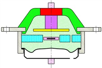
The single bell plate hydraulic mount depicted in Fig. 1(a) comprises several components: a main spring rubber, an inertia channel, a decoupler channel, a bell plate, and a rubber bottom membrane. The fluid flow chamber is divided into three sections: an upper chamber (main chamber), a bell plate chamber, and a lower chamber (compression chamber). Fluid flows from the upper chamber to the lower chamber through the bell plate, inertia channel, and/or decoupler channel. The main spring rubber provides a certain level of stiffness and damping to support the weight of the static engine. The upper chamber, bell plate chamber, and lower chamber of the hydraulic mount are filled with a mixture of antifreeze and water. When the hydraulic mount is externally stimulated (either by the engine or the road), pressure changes occur within the hydraulic mount chamber, causing the fluid to flow back and forth through the middle inertia channel and bell plate. This flow generates significant damping for the mount, dissipating the energy from external vibration and achieving vibration isolation. Simultaneously, when the hydraulic mount experiences external stimulation, fluid flows from the upper chamber to the lower chamber through the decoupler channel, with the flexible rubber membrane serving as an energy storage mechanism.
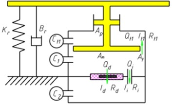
Fig. 1(b) illustrates a lumped parameter model of single bell plate hydraulic mount. When the hydraulic mount is excited by , the bell plate primarily addresses the issue of high-frequency hardening, especially when the fluid flow in the inertial channel is minimal. Consequently, it can be assumed that the flow rate () through the inertial channel is 0, along with an inertia coefficient () and damping coefficient () of 0.
Fig. 1Configuration of the bell plate hydraulic mount: a) schematic, b) physical model
a)
b)
The pressure difference between the top and bottom chambers is calculated based on the linear moment equation. To better illustrate the variation in effective area of the decoupling membrane under different excitation amplitudes, the parameter is introduced [18]. Assuming there is only one inertial channel, representing the vertical displacement of the engine, the overall equation of motion for single bell plate hydraulic mound can be written as Eq. (1-6), the symbols and values of the parameters of the hydraulic mount system are shown in Nomenclature:
The transmitted force is calculated in Eq. (7) and it is further used to calculate for the transmissibility and the dynamic stiffness. The transmissibility is the ratio between the transmitted force and the excitation force. The dynamic stiffness is the ratio between the transmitted force and the excitation displacement:
2.2. Single bell plate hydraulic fluid mount system for 1/4 vehicle model
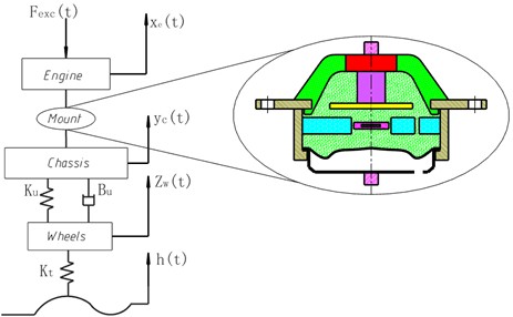
In practical applications, the engine mount system involves numerous parameter variables due to its complex structure. This system exhibits significant nonlinearity, making it challenging to develop comprehensive and accurate mathematical models. Consequently, it was necessary to disregard parameters that have minimal impact on control when studying the engine mount system. In this study, the influence of the seat in the cab, the engine's position, and the driver’s effect on the system during driving were neglected. The engine was modeled as a rigid body supported by spatial elastic elements, while the hydraulic mount was represented as an elastic damping component. The engine was connected to the vehicle body via the hydraulic mount, which in turn was attached to the chassis through the suspension system, with the chassis grounded through the wheels. Based on these assumptions, a 1/4 vehicle model featuring single bell plate hydraulic mount system, as depicted in Fig. 2, was developed.
Fig. 2Single bell plate hydraulic mount system model of 1/4 vehicle
The vertical motion equation of the engine, the body and the wheel can be written as Eq. (8-10), respectively:
where is the excitation of the engine, is the pavement incentive, , and represent the vertical displacement of the engine, the vertical displacement of the body and the displacement of the wheel, respectively. The parameters symbols of single bell plate hydraulic mount system of the 1/4 vehicle model were shown in Nomenclature. The vehicle dynamics model was implemented in MATLAB/Simulink® using the mount parameters outlined in Nomenclature.
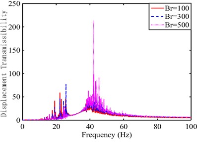
When subjected to two different sets of excitation to the 1/4 vehicle model system, where the random pavement incentive sine sweep signal was , where was the amplitude and was the frequency. Considering the real condition of the road surface, the frequency was in the range of 0.1 Hz-30 Hz, amplitude was 3 mm. The engine incentive sine sweep signal was , where was the amplitude of the engine’s exciting force and was the frequency. Considering the in-line four-cylinder excitation, was 1000 N and the value of ranged from 0 Hz to100 Hz. The numerical results were shown in Fig. 3(a) and 3(b), respectively.
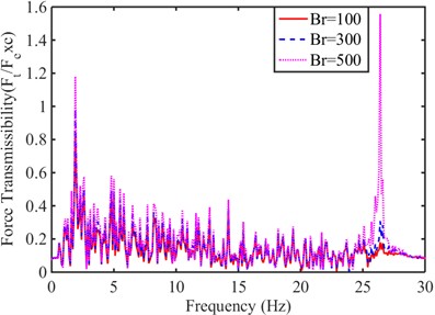
Fig. 3System transmissibility under sinusoidal sweep-frequency excitation signal
a) Force transmissibility
b) Relative displacement transmissibility
As observed from Fig. 3(a), when was 100, 300, and 500 N·s/m, the root mean square (RMS) of the force transfer rate was 10.8990, 13.8779, and 15.8623, respectively. This indicated that enhancing the damping of rubber main spring in the hydraulic mount can effectively suppress low-frequency, high-amplitude vibrations induced by the road surface [19]. For a damping coefficient of 500 N·s/m, the peak value of the relative displacement transfer rate was 210 within the 40-60 Hz range in Fig. 3(b). Separately, the RMS values of this transfer rate were 976.5189, 975.5267, and 975.0792 for Br values of 100, 300 and 500 N·s/m, respectively. This analysis demonstrated that optimal vibration isolation requires opposite damping strategies for different frequency bands: low damping for minimal force transfer rate at low frequencies, and high damping (despite its limited efficacy) for minimal displacement transfer rate at high frequencies. A significant drawback of increasing the damping coefficient Br was a substantial rise in the peak relative displacement transfer rate [20].
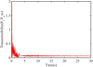
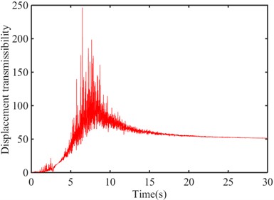
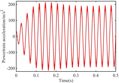
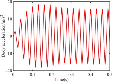
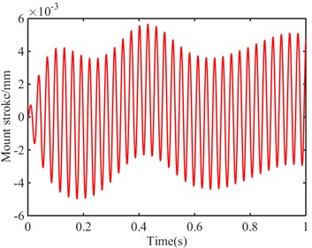
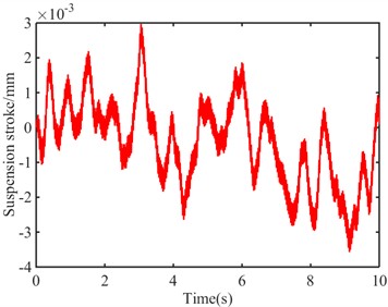
Taking 500 to analyze the time domain characteristics under the excitation of Grade A pavement, the force transfer rate reached equilibrium at 5 s and converges to 0.07772, as shown in Fig. 4(a). The relative displacement transmissibility reached equilibrium at 15 s and converges to 51.31, as shown in Fig. 4(b). The mean values of powertrain acceleration and body acceleration were 0.03175 and –0.002584 m/s2 in Figs. 4(c) and (d), respectively. The peak values of mount stroke and suspension stroke were 0.00712 and 0.003573mm in Figs. 4(e) and (f), respectively. When the bell plate hydraulic mount system was at high frequency, both the force transfer rate and the relative displacement transfer rate can rapidly converge, and the mount stroke and the suspension stroke were far less than the excitation amplitude.
To sum up, simulation results revealed the force transmissibility of the engine to the body and the relative displacement transmissibility of the body to the engine under different damping of the hydraulic mount rubber main spring [21]. The low damping rubber main spring should be used for single bell plate hydraulic mount system of 1/4 vehicle model. For consistency, a value of 100 was used in all subsequent analyses.
Fig. 4Vehicle response under a random pavement incentive
a) Force transmissibility
b) Relative displacement transmissibility
c) Powertrain acceleration
d) Body acceleration
e) Mount stroke
f) Suspension stroke
3. Influence of mass parameters , and on vibration isolation performance of mount
3.1. Four-cylinder engine excitation source
Based on the layout configuration adopted by the vast majority of modern passenger cars, which feature a transverse front-engine, front-wheel-drive (FF) arrangement, the crankshaft axis is oriented along the vehicle’s -direction, and the cylinder axes lie in the - plane with a caster angle . Under this configuration, the reciprocating inertia force component induces lateral (left-right) oscillation of the vehicle body and causes steering wheel judder in the lateral direction. The component induces vertical bounce of the vehicle body and results in seat and floor pan vertical vibration, which is the most sensitive excitation source in terms of ride comfort. The over-turning moment (reaction torque) induces pitch motion of the vehicle body, and serves as the primary excitation source for vehicle pitch during acceleration and deceleration events. In rare cases, a roll angle about the -axis may also be considered [22]. Among them, the excitation of the in-line four-cylinder engine was shown in Eq. (11):
The components were defined as follows: was the inertia force acting along the -axis, along the -axis, was the moment about the -axis, and was the moment about the -axis. The empirical formula related to engine speed and torque is commonly used, rather than the more precise order expansion, so the solution of excitation in each direction was shown in Eq. (12):
where was the mounting Angle of the in-line four-cylinder engine; was the mass of the engine piston rod; was the ratio of the length of the engine crank to the length of the connecting rod; was the crank throw; was the angular speed of engine crankshaft; was the distance between the center line of the 2 and 3 cylinders of a four-cylinder engine and the engine’s center of mass; was the average output torque of a four-cylinder engine; was roll angle about the -axis; was the torque fluctuation coefficient, with typical values for a four-cylinder engine in the range of 0.5-0.8.
3.2. Road excitation source
Vehicle road conditions were inherently random. The standard practice for describing this continuous random signal was to use its spatial frequency power spectral density function and the corresponding time domain representation [23]. According to GB/T7031-2005 “Mechanical Vibration Road Surface Spectrum Measurement Data Report”, the mathematical model of random road surface was Eq. (13):
where: was the unit white noise; was the reference spatial frequency, 0.1 m-1; was the pavement spectral value under the reference spatial frequency; was the speed of the car, m/s.
The road input signal of continuous vibration of A single wheel of a vehicle driving at 20 m/s on class A, B and C road surface was shown in Fig. 5.
Cars driving on different roads will inevitably encounter bumpy roads. Among them, the most typical bumpy road was the deceleration belt. The short and violent impact brought by the car driving on the bumpy road surface will bring a certain amount of serious impact to the engine. Considering the actual situation of the deceleration belt, half a sine wave was superimposed on the basis of the continuous road surface to represent the excitation of the deceleration belt road surface [24].
3.3. Influence of various mass configurations of , and
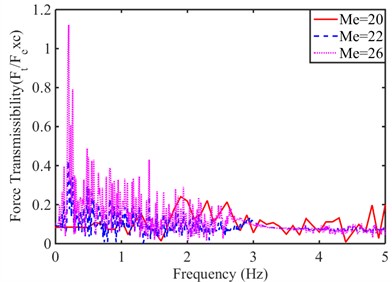
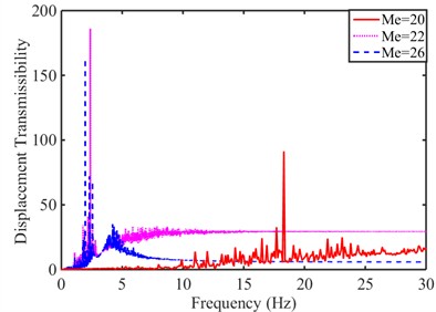
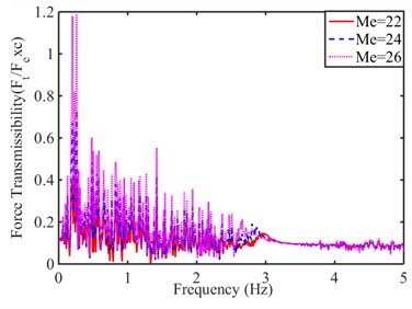
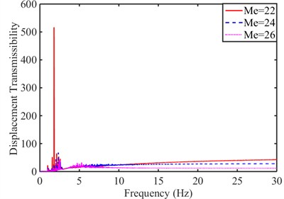
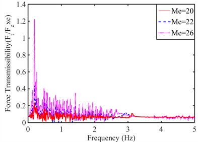
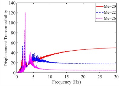
To simulate random pavement excitations under realistic driving conditions, a rational function white noise model was employed. The simulation parameters were set to a vehicle speed of 20 m/s, a duration of 10 seconds and a Class A road surface. The vibration isolation performance of the single bell plate hydraulic mount was evaluated used two key metrics: the force transmissibility from the engine to the body and the relative displacement transmissibility from the body to the engine. These metrics were analyzed to assess vibration isolation performance under varying mass conditions. Figs. 6-9 presented the comparison results of these two evaluation indicators for different values of , and , corresponding to various mass configurations.
Fig. 5Random pavement incentive
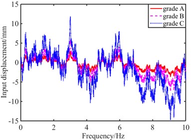
Fig. 6Comparative analysis of evaluation indexes when Mb= 225 kg and Mw= 10 kg
a) Force transmissibility
b) Relative displacement transmissibility
Fig. 7Comparative analysis of evaluation indexes when Mb= 185 kg and Mw= 12 kg
a) Force transmissibility
b) Relative displacement transmissibility
Fig. 8Comparative analysis of evaluation indexes when Mb= 265 kg and Mw= 8 kg
a) Force transmissibility
b) Relative displacement transmissibility
Fig. 9Analysis of evaluation indexes with different quality parameters
a) Force transmissibility
b) Relative displacement transmissibility
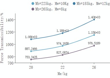
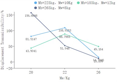
It was obvious from Fig. 9(a) that the comparison of RMS values of relative force transmissibility at different masses. Regardless of the sum of and , the relative force transmissibility increased with the increase of . Because was the primary inertial body of the system, increasing lowered its natural frequency, which caused the system to resonate within a lower frequency range. As shown in Figs. 6(a), 7(a), and 8(a), a larger resulted in a sharper resonance peak in the low-frequency band. Similarly, the comparison of RMS values of the displacement transmissibility at different masses was obvious as observed from Fig. 9(b). When the sum of and no more than 235 kg, with the increase of , the displacement transmissibility will peak when = 22. As shown in Figs 6(b), 7(b), and 8(b), it was confirmed that increasing reduces the displacement transmissibility in the high-frequency band.
As observed from Fig. 9(b), when the sum of and exceeds 235kg, with the increase of , the displacement transmissibility decreases sharply. When = 26, its RMS value is 10.899, which indicated that when the sum of and was large, the engine mass should be appropriately increased to reduce the force transmissibility. and represented the masses directly coupled to the excitation source. Together with the wheel stiffness, they formed a high-frequency resonance mode. From Figs. 6(b), 7(b), and 8(b), it can be observed that with a fixed , decreasing and raised the frequency of the high-frequency resonance peak and limited its amplitude to a higher band, thereby expanding the effective isolation range in common frequency bands. On the other hand, increasing and worsened the displacement transmissibility.
To achieve overall superior vibration isolation performance, it was essential to coordinate the relationship among the three masses. A typical strategy was to ensure sufficient for effective high-frequency attenuation while minimizing and to shift detrimental resonance peaks to higher frequencies. The following parameters were adopted in all subsequent studies: = 265 kg, = 8 kg, = 22 kg.
4. Influence of pavement incentive
4.1. Random pavement incentive
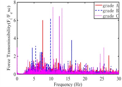
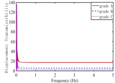
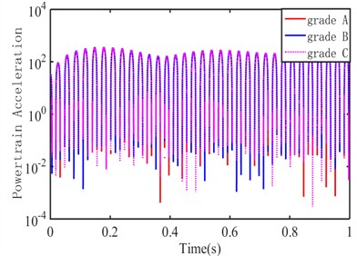
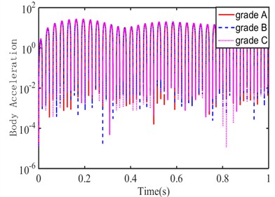
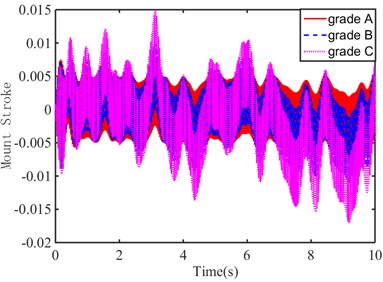
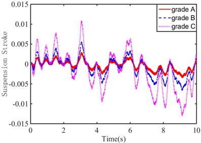
In order to further analyze the vibration isolation performance of single bell plate hydraulic mount, simulations were conducted with a vehicle speed of 20 m/s over a duration of 10 s under road roughness classifications A, B, and C. The corresponding average road roughness coefficients for Class A, B, and C were 16, 64, and 256, respectively. The simulation results were presented in Fig. 10.
Fig. 10Vehicle response under random pavement incentive
a) Force transmissibility
b) Relative displacement transmissibility
c) Powertrain acceleration
d) Body acceleration
e) Mount stroke
f) Suspension stroke
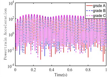
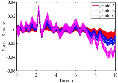
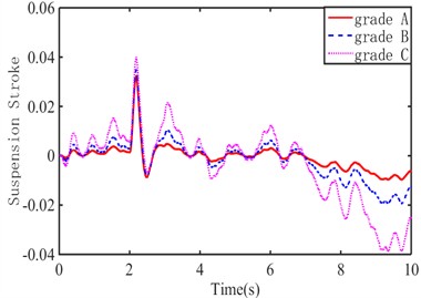
As shown in Figs. 10(a), (e), and (f), the peak force transmissibility from the engine to the body increased with road roughness, reaching values of 6.014, 6.203, and 7.485 on Grade A, B, and C pavements, respectively. The mount stroke and suspension stroke peaks followed the same trend, with mount stroke peaks of 0.008364, 0.01102, and 0.01706, and suspension stroke peaks of 0.003518, 0.006692, and 0.01304 for Grade A, B, and C pavements, respectively.
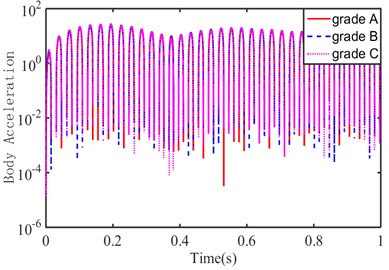
As observed from Fig. 10(b), the relative displacement transmissibility of the body and engine rapidly converged to A certain value with the increase of road roughness. The fixed values were 17.26, 5.7 and 2.496 for grade A, B and C pavements, respectively, which showed a decreasing trend. As observed from Figs. 10(c) and (d), pavement grade had almost no effect on powertrain acceleration and body acceleration.
In summary, the force transmissibility, the mount stroke, and the suspension stroke were positively correlated with the random pavement incentive. Large-amplitude excitation may activate nonlinear stiffness, thereby altering the system's effective natural frequency and consequently affecting the shape and peak positions of the transmissibility curve. The vibration isolation effect of the bell plate hydraulic mount was mainly reflected in the relative displacement transmissibility between the body and the engine, which can maintain a good control effect when random pavement incentives increase.
4.2. Impact fluctuating pavement incentive
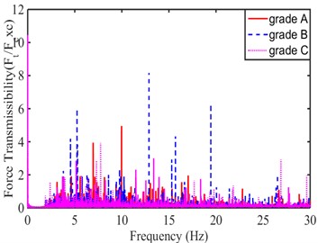
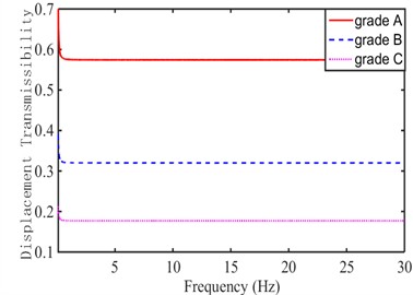
In order to further verify the superiority of the bell plate hydraulic mount performance, A short-time, high-strength impact wave road surface was selected as the incentive input, and the vehicle was set to pass the speed reducer on the A, B, and C roads at a speed of 2 m/s, respectively, and the parameter driving time of the impact wave road surface was set to 10 s. The parameters were numerically calculated under single bell plate hydraulic mount system of the 1/4 vehicle model, as shown in Fig. 11.
As shown in Figs. 11(a), (e), and (f), the peak values of force transmissibility, mount stroke, and suspension stroke under impact-fluctuating pavement excitation followed a trend similar to that observed under random pavement excitation. Compared with Fig. 10(a), the peak force transmissibility increased by –17.6 %, 31.6 %, and 39.7 % on Grade A, B, and C pavements, respectively, when a deceleration belt was introduced. Relative to Fig. 10(e), the peak mount dynamic travel rose by factors of 2.61, 1.93, and 1.45 on the corresponding pavement grades with the deceleration belt. Similarly, in contrast to Fig. 10(f), the peak suspension stroke increased by factors of 8.28, 4.25, and 2.07 for Grade A, B, and C pavements with the deceleration belt. The introduction of a deceleration belt led to a marked amplification in both mount and suspension displacements across all pavement grades, while the effect on force transmissibility varied with pavement roughness. The amplification factors generally decreased as pavement roughness increased (from Grade A to C), suggesting a nonlinear interaction between excitation severity and system response.
As shown in Fig. 11(b), the relative displacement transmissibility between the body and engine rapidly converged to a fixed value as road roughness increases. These convergence values were 0.5743, 0.320, and 0.1772 for Grade A, B, and C pavements, respectively, which showed clear decreasing trend. Compared with Fig. 10(b), the peak relative displacement transmissibility between the body and engine decreased by 96.7 %, 94.4 %, and 92.9 % on Grade A, B, and C pavements, respectively, when a deceleration belt was added. The deceleration belt effectively suppressed the peak dynamic relative displacement between the body and engine, with the mitigation effect being most pronounced on smoother pavements (Grade A) and slightly less effective as pavement roughness increased, though still maintaining over 92 % reduction even on the roughest surface (Grade C).
As observed from Figs. 11(c) and (d), the powertrain acceleration and body acceleration were largely unaffected by pavement grade. The simulation results indicated that pavement roughness (Grade A, B, and C) had negligible influence on both powertrain and body acceleration responses under the evaluated conditions.
To sum up, the force transmissibility from the engine to the body, the mount stroke, and the suspension stroke were still positively correlated with the impact of fluctuating pavement incentives. The vibration isolation effect of single bell plate hydraulic mount was mainly reflected in that the peak value increase rates for the force transmissibility, the relative displacement transmissibility of body and engine, the mount stroke, and the suspension stroke were decreased with the increase of road roughness. The deceleration belt induced strong and roughness-dependent amplifications in mount/suspension motions while effectively suppressing body-engine relative displacement, yet it did not notably alter acceleration responses regardless of pavement roughness level.
Fig. 11Vehicle response under impact fluctuating pavement incentive
a) Force transmissibility
b) Relative displacement transmissibility
c) Powertrain acceleration
d) Body acceleration
e) Mount stroke
f) Suspension stroke
5. Conclusions
The objective of this research was to develop the damping performance of single bell plate hydraulic mount of the 1/4 vehicle model, accomplishing the following goals:
1) For single bell plate hydraulic mount system of a 1/4 vehicle model, when 3.39×10⁴ N/m, 2500 N·s/m, 2.5×10⁵ N/m, and is 100 N·s/m, the minimum force transmissibility can be obtained in the low-frequency region, and its RMS was 10.8990; in the high-frequency region, small relative displacement transitivity can also be achieved, with an RMS of 976.5189.
2) If the three mass parameters of , , and were properly matched, a smaller force transmissibility from the engine to the body and the relative displacement transmissibility between the body and the engine can be obtained. When = 265, = 8, and = 22, The RMS values of force transmissibility from the engine to the body and the relative displacement transmissibility between the body and the engine were 51.948 and 827.0874, respectively.
3) Under random pavement incentive, the force transmissibility from the engine to the body, mount stroke, and suspension stroke all exhibited a positive correlation with road roughness. The relative displacement transmissibility from the engine to the vehicle frame decreased with the increase of road roughness, and the value on the B and C road surface decreases by 67.0 % and 85.5 % compared with that on the A road surface, respectively.
4) Compared with the impact pavement incentive and random pavement excitation, the peak value of force transmissibility on class A, B and C pavement increased by –17.6 %, 31.6 %, and 39.7 %, respectively; the amplitude peaks of relative displacement transmissibility from engine to body decreased by 96.7 %, 94.4 %, and 92.9 % respectively. The peak of mount dynamic travel increased by 2.61 times, 1.93 times, and 1.45 times respectively. The peak of suspension dynamic travel increased 8.28 times, 4.25 times, and 2.07 times respectively. Although road roughness increased, bell plate hydraulic suspension still maintained a good control effect.
This study evaluated the vibration isolation performance of a single bell plate hydraulic mount within a quarter-car model. The analysis examined 6 key parameters (including force transmissibility and relative displacement transmissibility) under varied damping conditions of the main rubber spring, different combinations of engine, body, and tire masses, as well as different road excitation profiles. However, when assessing the effect of mass parameters, the influence of the hydraulic mount’s own mass, stiffness, and damping as a coupled tuned system on transmissibility was not considered. Future work will extend the evaluation to a half-car model to further verify the practical feasibility of this mount configuration. Also, different weight matching among , and affected the force transmissibility and displacement transmissibility, the optimal set of parameters would be a key research focus.
The present work is purely computational and analytical. All simulation results are obtained from theoretical models and parameter values derived from typical engineering practice and published literature. No experimental measurements – such as in-cylinder pressure data, mount dynamic stiffness tests, or vehicle-level vibration validation – have been performed to verify the predicted responses. Consequently, the quantitative accuracy of the results depends directly on the fidelity of the input parameters and model assumptions. To address the above limitations and extend the current work, the following research directions are recommended. Comprehensive experimental campaigns should be conducted to validate the proposed models. Measuring in-cylinder pressure curves to derive accurate excitation forces, characterizing mount dynamic stiffness and damping over a wide frequency and amplitude range, performing vehicle-level vibration measurements (accelerometers on engine mounts, subframe, and body) under controlled driving conditions to compare with simulation predictions.
References
-
J. Hu, D. Zhu, J. Chen, and W. Li, “Refined response axis decoupling axiom for a coupled vibrating system with spectrally-varying mount properties,” Journal of Vibration and Control, Vol. 24, No. 15, pp. 3233–3248, Oct. 2017, https://doi.org/10.1177/1077546317735941
-
H. Marzbani, R. N. Jazar, and M. Fard, “Hydraulic engine mounts: a survey,” Journal of Vibration and Control, Vol. 20, No. 10, pp. 1439–1463, Apr. 2013, https://doi.org/10.1177/1077546312456724
-
Y. Yu, N. Naganathan, and R. Dukkipati, “A literature review of automotive engine mount systems,” Mechanism and Machine Theory, Vol. 36, No. 1, pp. 123–142, 2001.
-
M. Wang, G.-F. Yao, J.-Z. Zhao, and M. Qin, “A novel design of semi-active hydraulic mount with wide-band tunable notch frequency,” Journal of Sound and Vibration, Vol. 333, No. 8, pp. 2196–2211, Jan. 2014, https://doi.org/10.1016/j.jsv.2013.12.004
-
N. Vahdati, A. Alteneiji, F. F. Yap, and O. Shiryayev, “Amplitude-sensitive single-pumper hydraulic engine mount design without a decoupler,” Applied Sciences, Vol. 14, No. 6, p. 2568, Mar. 2024, https://doi.org/10.3390/app14062568
-
R. Tikani, N. Vahdati, and S. Ziaei-Rad, “Two-mode operation engine mount design for automotive applications,” Shock and Vibration, Vol. 19, No. 6, pp. 1267–1280, Jan. 2014, https://doi.org/10.1155/2012/651591
-
R.-L. Fan, Z.-N. Fei, B.-Y. Zhou, H.-B. Gong, and P.-J. Song, “Two-step dynamics of a semiactive hydraulic engine mount with four-chamber and three-fluid-channel,” Journal of Sound and Vibration, Vol. 480, p. 115403, Apr. 2020, https://doi.org/10.1016/j.jsv.2020.115403
-
A. R. Ohadi and G. Maghsoodi, “Simulation of engine vibration on nonlinear hydraulic engine mounts,” Journal of Vibration and Acoustics, Vol. 129, No. 4, pp. 417–424, Aug. 2007, https://doi.org/10.1115/1.2748459
-
F. Fallahi, R. Shabani, G. Rezazadeh, and S. Tariverdilo, “A modified design for hydraulic engine mount to improve its vibrational performance,” Proceedings of the Institution of Mechanical Engineers, Part C: Journal of Mechanical Engineering Science, Vol. 235, No. 23, pp. 6724–6736, 2021, https://doi.org/10.1177/09544062211000081
-
Y. Liu, X. Guan, P. Lu, and R. Guo, “Simulation research on dynamic characteristics of hydraulic mount,” Chinese Journal of Mechanical Engineering, Vol. 34, No. 1, p. 49, 2021, https://doi.org/10.1186/s10033-021-00571-6
-
R. Guo and Z.-W. Zhou, “Non-linear modeling and parameter identification of semi-active engine mounts with air spring,” Journal of Vibration and Acoustics, Vol. 142, No. 1, p. 011018, Feb. 2020, https://doi.org/10.1115/1.4045267
-
R. Fan and Z. Lu, “Fixed points on the nonlinear dynamic properties of hydraulic engine mounts and parameter identification method: experiment and theory,” Journal of Sound and Vibration, Vol. 305, No. 4-5, pp. 703–727, 2007, https://doi.org/10.1016/j.jsv.2007.04.045
-
Z. Lin and Y. Huang, “Effect of bell plate structure on high – and low-frequency characteristics of hydraulic mount,” Applied Rheology, Vol. 34, No. 1, p. 20240014, Sep. 2024, https://doi.org/10.1515/arh-2024-0014
-
Z. H. Lin, M. Z. Wu, and Y. X. Chen, “Dynamic characteristic analysis of new bell plate controllable multi-inertia channel MRF mount with wide frequency isolation,” Experimental Techniques, Vol. 47, No. 1, pp. 327–342, Jan. 2022, https://doi.org/10.1007/s40799-021-00539-0
-
Z. Lin, Y. Chen, M. Wu, and F. Zheng, “New bell plate controlled multi-inertia channel magnetorheological fluid mount wide frequency vibration isolation control study,” Journal of Intelligent Material Systems and Structures, Vol. 35, No. 8, pp. 775–788, Feb. 2024, https://doi.org/10.1177/1045389x241233352
-
Y.-C. Zhu, G.-F. Yao, M. Wang, H. Yu, K.-Y. Gao, and P.-L. Zhou, “Design and analysis of a new semiactive hydraulic mount for a wide-range tunable damping without magneto-rheological/electric-rheological fluid,” Applied Sciences, Vol. 13, No. 19, p. 10636, 2023, https://doi.org/10.3390/app131910636
-
J. Hu, Y. Li, P. Jiang, and L. Zhao, “Architectural design and robust optimization of adaptive hydraulic engine mount,” Journal of the Brazilian Society of Mechanical Sciences and Engineering, Vol. 46, No. 3, p. 128, Feb. 2024, https://doi.org/10.1007/s40430-023-04653-5
-
Z. Lin, Y. Huang, and P. Zhang, “Optimization of dynamic characteristics and vibration isolation control for bell plate magnetorheological fluid mount,” Smart Materials and Structures, Vol. 35, No. 4, p. 045020, Apr. 2026, https://doi.org/10.1088/1361-665x/ae57ef
-
X.-A. Liu, J. Sun, W. Shi, X. Qian, D. Chen, and G. Chen, “Modeling and analysis of high-frequency dynamic characteristics of double isolation rubber mounts,” Proceedings of the Institution of Mechanical Engineers, Part D: Journal of Automobile Engineering, Vol. 238, No. 4, pp. 620–632, 2022, https://doi.org/10.1177/09544070221133877
-
C. Liu, W. Zhang, K. Yu, T. Liu, and Y. Zheng, “Quasi-zero-stiffness vibration isolation: designs, improvements and applications,” Engineering Structures, Vol. 301, p. 117282, Dec. 2023, https://doi.org/10.1016/j.engstruct.2023.117282
-
B. Barszcz, J. T. Dreyer, and R. Singh, “Experimental study of hydraulic engine mounts using multiple inertia tracks and orifices: narrow and broad band tuning concepts,” Journal of Sound and Vibration, Vol. 331, No. 24, pp. 5209–5223, Aug. 2012, https://doi.org/10.1016/j.jsv.2012.07.001
-
X. Zhao, Z. Yang, B. Pan, R. Wang, and L. Wang, “Analysis of excitation source characteristics and their contribution in a 2-cylinder diesel engine,” Measurement, Vol. 176, p. 109195, Feb. 2021, https://doi.org/10.1016/j.measurement.2021.109195
-
Y. Liu, Z. Zhao, F. Guo, and Y. Fu, “Vibration control of an axially moving accelerated/decelerated belt system with input saturation,” Transactions of the Institute of Measurement and Control, Vol. 40, No. 2, pp. 685–697, Oct. 2016, https://doi.org/10.1177/0142331216665685
-
D. Barta, M. Blatnický, A. Lovska, S. Kowalski, A. Slíva, and J. Dižo, “Dynamic responses of a single-axle trailer when driving over a road obstacle,” Sensors, Vol. 25, No. 17, p. 5246, Aug. 2025, https://doi.org/10.3390/s25175246
About this article

This work was supported in part by Supported by the Open Project Program of Fujian Key Laboratory of Special Intelligent Equipment Measurement and Control, Fujian Special Equipment Inspection and Research Institute, China (No. FJIES2024KF17), Natural Science Foundation of Fujian Province (Grant No.: 2024J01317, Grant No.: 2026J0011112) and Central Guidance Science and Technology Development Projects (Grant No.: 2022L3044).
The datasets generated during and/or analyzed during the current study are available from the corresponding author on reasonable request.
Jian Wei: Conceptualization, methodology, investigation, data curation, writing-original draft. Zhihong Lin: software, formal analysis, visualization, writing-review and editing, funding acquisition. Yuedong Huang: supervision, project administration.
The authors declare that they have no conflict of interest.