Abstract
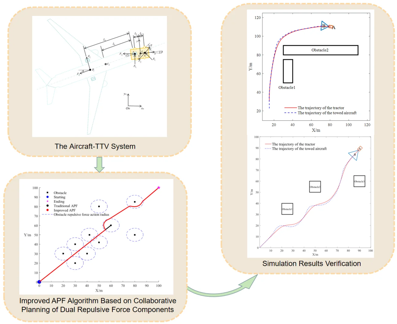
To enhance the maneuvering efficiency and safety of the aircraft towbarless towing vehicle (TTV) system, this study presents an optimized path planning method based on an improved artificial potential field (APF) algorithm. First, comprehensive kinematic and dynamic models are established, incorporating both lateral and yaw motions of the TTV system. Second, to mitigate obstacle interference challenges in complex airport environments, the proposed method introduces an innovative relative-distance safety factor and implements a dual-repulsive-force cooperative planning strategy, effectively overcoming the traditional APF algorithm’s limitations regarding goal unreachability and local minima. Furthermore, the integration of Bézier curves ensures curvature continuity in the planned path, thereby maintaining compliance with kinematic constraints. Finally, a constrained-motion TTV simulation model is developed to validate the algorithm’s performance. Simulation results demonstrate that, in static obstacle scenarios, the proposed method successfully enables autonomous path planning, generating smooth and collision-free trajectories. This approach offers a robust solution for ensuring stable and reliable operation of the TTV system in real-world airport environments.
Highlights
- Introducing a relative distance safety factor and a dual repulsive force collaborative planning strategy to improve the APF algorithm, resolving goal unreachability and local minima issues.
- Applying Bézier curves for curvature-continuous processing of planned paths.
- Enabling autonomous planning of collision-free smooth trajectories for the aircraft-TTV system in static obstacle scenarios.
1. Introduction
As the core equipment of airport ground support systems, aircraft towing vehicles undertake the critical task of transferring aircraft between hangars, boarding bridges, apron areas, and maintenance workshops [1]. Towing systems are primarily classified as towbar-type or towbarless, depending on the connection mechanism. Compared with conventional towbar-type systems, towbarless towing vehicles (TTVs) exhibit superior performance in constrained operational environments owing to their simplified procedures, exceptional maneuverability, and minimized wear on aircraft tires. These advantages have driven a significant rise in their market adoption across the aviation industry over the past decade.
However, current aircraft towing operations remain dependent on a ‘TTV-marshaller’ human-machine coordination mechanism, which suffers from limitations due to operator expertise, resulting in persistent issues such as prolonged response delays and elevated safety risks. Statistical analysis of 370 representative accidents from the Aviation Safety Network (ASN), NTSB accident database, and the Aviation Herald reveals that ground collisions or ground handling incidents account for 7 % of total aviation accidents but contribute to 12 % of aviation fatalities, incurring annual global economic losses exceeding $11 billion [2]. More critically, conventional towing practices extend aircraft ground idle time, leading to increased non-productive fuel consumption (estimated at 80-120 liters/hour for wide-body engines in taxiing mode) and contributing to elevated airport noise pollution levels (with sound pressure exceeding 85 dB(A) during prolonged low-thrust operations). These inefficiencies directly conflict with the safety and sustainability goals of modern airport operations, as evidenced by recent ICAO environmental impact assessments [3]. Although semi-autonomous remote-controlled towing technologies have been explored experimentally in several countries, technical and operational barriers continue to hinder realization of fully autonomous operations. Despite active international research efforts in this domain, no mature technological solutions have yet emerged. Thus, the development of highly reliable and energy-efficient autonomous towing systems to improve both safety margins and operational efficiency in aviation ground handling remains an unresolved challenge requiring innovative solutions.
Currently, path planning algorithms commonly employed in aircraft-TTV systems include the graph-search-based A* algorithm [4], sampling-based methods such as the Probabilistic Road Map (PRM) [5] and Rapidly-exploring Random Tree (RRT) [6], biologically inspired Genetic Algorithms (GA) [7], and the virtual-force-field-model-based Artificial Potential Field (APF) [8]. Significant progress has been made in optimizing these algorithms. Chai et al. [9] proposed an algorithm that fuses Deep Reinforcement Learning’s Deep Deterministic Policy Gradient (DDPG) with APF. This approach utilizes DDPG’s dynamic adjustment mechanism to optimize the repulsion and attraction parameters of the APF algorithm, thereby enhancing path planning efficiency. Jiang et al. [10] proposed an adaptive potential field adjustment mechanism based on the relative distance between the real-time target position and the operational goal, achieving effective path planning through virtual local targets. While these methods successfully address path generation, they often neglect trajectory smoothing during system operation. Guan et al. [11] incorporated the APF algorithm into the bidirectional RRT* algorithm proposing the BIAP-RRT* algorithm, which improves the convergence speed. Focusing specifically on aircraft-TTV systems, Zhang et al. [1] incorporated collision warning mechanisms and minimum turning radius constraints into the A* algorithm through precise kinematic modeling, generating feasible trajectories aligned with TTV dynamics. Similarly, Yang et al. [12] improved autonomous obstacle avoidance in structured environments by integrating route boundary influence factors into the repulsive potential field function.
Aiming at the particularities of aircraft ground handling scenarios, this study focuses on the path planning problem for TTV systems and proposes an improved APF algorithm incorporating kinematic constraints. The objective is to generate an optimal path that meets high safety standards, operational efficiency, and dynamic feasibility in complex environments. The specific contributions include: First, a mathematical motion model of the towing system is established, with detailed force analysis characterizing the motion behavior of the aircraft-TTV composite. Second, a relative-distance safety factor and a dual-repulsive component cooperative planning strategy are introduced to resolve the traditional APF algorithm’s issues of goal unreachability and local minima, thus ensuring the global planning validity. Third, to meet practical engineering requirements for path smoothness, a Bézier curve-based parametric smoothing method with curvature continuity processing is proposed, eliminating abrupt steering maneuvers and guaranteeing continuous differentiability of the towing trajectory. Finally, simulation experiments integrating the model and algorithm verify the proposed method’s effectiveness. The study aims to provide a reliable path planning solution for aircraft towing processes, ensuring both safety and operational efficiency.
2. Model of aircraft-TTV system
The TTV uses its own clamping and lifting device to directly engage with the aircraft’s nose landing gear, positioning the vehicle beneath the front section of the aircraft [13]. For modeling purposes, trajectory planning for the towing system model is occurred on a flat and horizontal ground surface with no inclination. Vibrations perpendicular to the ground and deformations of the TTV system during operation are neglected. Consequently, this study considers only the motion of the model within a two-dimensional plane.
2.1. Coordinate system of the aircraft-TTV system
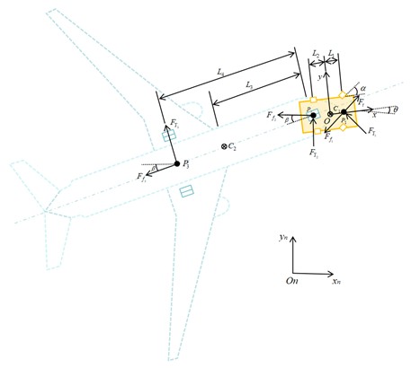
The kinematic model of the TTV system is illustrated in Fig. 1. The symbols used in the Fig. 1 and formulas of Section 2 of the article are all listed in Table 1. The coordinate system definition follows to a right-handed Cartesian framework, with the inertial coordinate system - fixed on the ground and its origin located at a fixed point on the ground. The TTV coordinate system - is established with its origin at the TTV’s center of mass, where the , axis correspond to the longitudinal, lateral directions of the TTV system, respectively.
Table 1Symbol description
Variable | Description |
, | The centroid positions of the TTV and aircraft |
, | The distances from the TTV’s front axle and rear axle to its centroid |
, | The distances from the TTV’s rear axle to the aircraft’s centroid and the aircraft’s rear axle |
, , | The midpoints of the TTV’s front axle, the connection point between the TTV and the aircraft, the midpoints of aircraft’s rear axle, respectively |
The heading angle of the TTV | |
The steering angle of the TTV’s front wheels | |
The angle between the TTV and the aircraft | |
, , | The rolling resistances acting on the TTV’s front wheels, rear wheels, and the aircraft’s rear wheels, respectively |
, , | The lateral forces acting on the TTV’s front wheels, rear wheels, and the aircraft’s rear wheels, respectively. |
The centroid position vector of the TTV in the - coordinate system | |
The velocity of the TTV | |
, | The yaw rate of the TTV and the aircraft |
, | The masses of the TTV and the aircraft |
, | The instantaneous acceleration vectors of the TTV and the aircraft |
The driving force of the system | |
The unit vector of the TTV’s front wheel orientation in the - coordinate system | |
, | The unit vectors along the -axis and -axis in the - coordinate system |
The rolling resistance force vector of the TTV relative to the aircraft’s angle in the - coordinate system | |
, | The lateral constraint force vectors acting on the TTV’s front wheel and the center of the aircraft’s rear axle in the - coordinate system |
, , | The velocity vectors at points , , and |
, , , | The displacement vectors between points , , , and |
The air resistance coefficient | |
The air density | |
The frontal area |
For aircraft modeling, the following assumptions are made: (1) the aircraft is treated as a rigid body. (2) The landing gear is perfectly rigid. (3) Both geometric configuration and mass distribution exhibit symmetry about the longitudinal central plane. Additionally, the TTV is modeled as a rigid body, neglecting the elastic damping effects of components such as the suspension and shock absorbers. Given that the TTV system operates on well-maintained airport runways, pitch, roll, and vertical degrees of freedom are disregarded. Thus, the motion of the aircraft-TTV system is described as the translational and yaw movements of coordinate system relative to - ,with the coordinate transformation given by [14]:
Fig. 1Schematic diagram of force distribution in the aircraft-TTV system
2.2. Kinematic and dynamic analysis of the TTV system
The longitudinal forces acting on the towing system include the traction force on the TTV, air resistance force, and Combined rolling resistance and lateral constraint forces. Thus, the towing system’s equation of motion derived from Eq. (1) is [15]:
where is the traction force in the longitudinal direction:
where provides the traction force for the TTV system, and ensures that the thrust direction is always consistent with the rolling direction of the front wheels.
represent the force vectors acting on the TTV’s front wheels, rear axle center, and the aircraft’s rear axle center, respectively, which are represented as the rolling resistance along the longitudinal direction of the vehicle body and the lateral constraint force for preventing tire slippage, as shown in Eq. (4):
, , and satisfy the following relationship:
signifies the aerodynamic resistance acting on the entire towing system, and its equation is given as:
When the towing system performs a turning maneuver, the significant angular difference between the TTV and the aircraft, coupled with the relatively low operating speed of the system, results in a corresponding reduction in air resistance. Consequently, Eq. (6) is no longer applicable under such conditions.
3. Path planning algorithm for the aircraft-TTV system
In aircraft ground handling operations, the TTV system path planning must adapt to airport apron environment. It must simultaneously address the multi-modal obstacle distribution (including stationary aircraft, ground support equipment, and temporary facilities), while meeting the stringent safety requirements of aircraft towing operations. The APF algorithm offers significant environmental adaptability due to its intuitive physical field modeling and computational efficiency. By constructing a coupled attractive-repulsive potential field, it effectively achieves coordinated control between obstacle avoidance and target approach. Its differential equation-driven path generation mechanism ensures high computational efficiency. Combining theoretical rigor with engineering practicality, make the APF algorithm an ideal solution for aircraft-TTV path planning in complex environments.
3.1. APF algorithm
The APF algorithm, proposed by Khatib, has been widely applied in applications ranging from aerial vehicle formation control to autonomous ground vehicle path planning. For the aircraft-TTV systems, the algorithm abstracts the TTV as a moving particle within the potential field, enabling navigation through dual-field coupling effects: The target position generates an attractive potential field whose magnitude decreases with the TTV’s distance, creating a gradient vector field directed toward the destination. Obstacles generate repulsive potential fields, establishing collision-avoidance barriers. The resultant force vector field, obtained by superimposing these potential fields, dictates the vehicle’s trajectory. Applying the gradient descent method, the system identifies the minimum-energy path that simultaneously avoids obstacles and converges asymptotically to the target. This approach efficiently generates fast and collision-free safe paths around obstacles. As illustrated in Fig. 2, the potential field force distribution of the towing system clearly demonstrates the spatial superposition characteristics of the attractive-repulsive fields and their path-forming guidance mechanism.
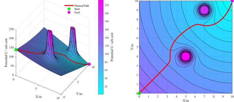
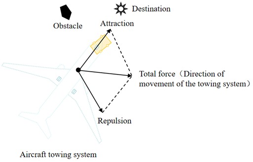
In the physical representation of the APF algorithm, the repulsive and attractive potential fields form a sharp contrast through terrain metaphor: the repulsive field corresponds to a high-potential-energy region, resembling steeply rising peaks that repel moving objects; while the attractive field represents a low-potential-energy region, analogous to gently sloping valleys that continuously attract objects toward the target point. Through vector superposition, these two potential fields combine to form a directional composite potential field (as shown in Fig. 3), whose gradient direction of which determines the planned path direction of the towing system.
Fig. 2Schematic diagram of force analysis in the APF model
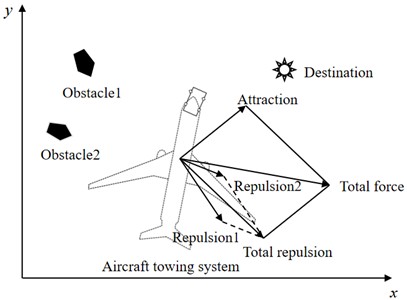
Fig. 3Schematic of the composite potential field showing gradient directions and potential distribution
3.1.1. Attractive potential field function
In the motion control design of the APF algorithm, the magnitude of attractive force is linearly proportional to the Euclidean distance between the towing system and the destination: as the distance increases, the attraction exhibits a monotonically increasing trend; when the towing system approaches the target point, the amplitude of attraction gradually decays until it reaches zero. The attractive potential field function is shown in Eq. (7):
where is the attractive gain coefficient, denotes the position of the towing system, and signifies the position of the destination, is the distance between the towing system and the destination.
The attractive force is derived as the negative gradient of the potential field:
3.1.2. Repulsive potential field function
In the obstacle modeling of the APF algorithm, the repulsive potential field is modeled as a nonlinear exclusion field based on safety distance: when the towing system is outside the obstacle’s influence range, the repulsive force t is zero; when entering the effective range, an inverse relationship exists between the Euclidean distance from the obstacle and the repulsive force magnitude, the repulsive force increases linearly as the distance decreases, and gradually diminishes as the distance grows. The total repulsive potential field is the linear superposition of individual obstacle repulsive potential fields, and the total repulsive force is the vector sum of repulsive forces from all obstacles. The repulsive potential field function is defined in Eq. (9):
where represents the repulsive gain coefficient, denotes the obstacle’s position, denotes the distance between the obstacle and the towing system, and is the repulsive force action radius.
The repulsive force is the negative gradient of the repulsive potential field, as shown in Eq. (10):
The total potential field combines the attractive and the repulsive components, as shown in Eq. (11):
where represents the number of obstacles.
3.1.3. Limitations of the traditional APF algorithm
In path planning, a towing system using traditional APF algorithm follows the principle of potential energy gradient descent, moving along the direction of decreasing potential energy until reaching the destination or encountering convergence, while theoretically guaranteeing convergence [16]. Nevertheless, due to the limitations of gradient descent method, the towing system is prone to fall into local minima solutions: when the towing system operates at a certain point on the path, if the magnitudes of attractive and repulsive forces are equal but opposite in direction, the resultant force vanishes. This leads to a force-free state where the towing system stops receiving forces, causing it to enter a stagnation state where it can neither continue moving or adjust its path. Such forced stagnation disrupts towing system’s operational continuity on airport surfaces, as illustrated in Fig. 4.
In addition, the traditional APF algorithm also suffers from the drawback of goal unreachability: when obstacles are proximal to the destination, the attraction from the destination weakens while the repulsion from obstacles intensifies. This interaction between attraction and repulsion forces causes the towing system to approach but fail to precisely reach the parking position, ultimately resulting in docking alignment deviation. This significantly disrupts airport ground operation scheduling processes, with the unreachable destination scenario illustrated in Fig. 5.
Fig. 4Local minima phenomenon in path planning
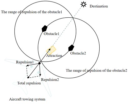
Fig. 5Goal unreachability scenario
3.2. Improved APF algorithm
3.2.1. Modified attractive potential field function
For large-scale airport path planning, when the towing system is still far from the destination, the attraction force on the towing system increases while the repulsion force relatively weakens. Under these conditions, the towing system may ignore obstacle avoidance requirements due to excessive attraction, thereby increasing the risk of collision with obstacles. The attractive function is optimized and adjusted as follows: When the operational radius of the airport extends to a certain range (i.e., when the Euclidean distance () between the towing system and the target point exceeds a critical distance threshold ), it is defined as the far-field navigation mode. In this mode, the magnitude of attraction is set to be inversely proportional to the distance between the towing system and the destination, ensuring that the attraction decreases when the towing system is far from the destination. As the towing system gradually approaches the destination (i.e., ), it switches to the near-field docking mode. Here, the original definition of the attractive function is retained, allowing the attraction to gradually increase. This ensures that the aircraft can quickly and safely reach the destination while avoiding obstacles during the final docking phase, thereby improving safety and maneuvering speed and making it suitable for the complex operational environment of airports. The improved attractive potential field function is:
where is the critical distance threshold between the towing system and the destination.
The corresponding improved attraction function expression is:
3.2.2. Enhanced repulsive potential field function
To address the unreachable destination problem in traditional APF algorithm, a relative distance safety factor between the towing system and destination is incorporated into the repulsive potential field function, ensuring the towing system maintains a safe distance from obstacles during operation. The improved repulsive potential field function is:
where relative distance safety factor .
The corresponding repulsive force expression is:
where and are the two repulsive force components of , as shown in Eq. (16):
According to Eq. (15), modulates the repulsive force growth rate to mitigate excessive repulsive potential influence when approaching the destination, enabling the towing system to smoothly approach the destination in the final stage. When the towing system reaches the destination, both attraction and repulsion forces simultaneously reduce to zero, ensuring successful aircraft docking and meeting the reliability requirements of airport ground operations.
3.2.3. Repulsive Force Direction Optimization
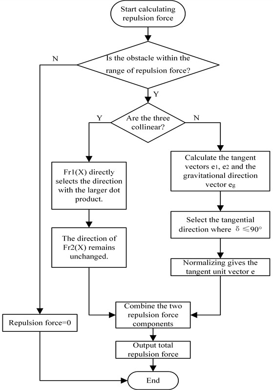
The aforementioned improvements still cannot fully overcome the inherent local minima problem of the traditional APF algorithm. To address this, this study proposes an improved strategy based on the collaborative planning of dual repulsive force components. The key steps for modifying the repulsive force direction are as follows:
(1) Parameter input: , , , .
(2) Modification of repulsive force direction: When , . When , the direction of is modified from pointing from the obstacle to the towing system to aligning with the tangential direction of the obstacle’s influence zone, while ensuring the angle between and the attractive force remains ≤ 90°. Meanwhile, maintains its original orientation, consistently pointing from the aircraft-TTV system toward the destination without alteration.
(3) Direction Vector Calculation:
1) Based on the spatial positional relationship between the obstacle and the towing system, two orthogonal tangential unit vectors are constructed from the displacement vector pointing from the obstacle to the system: where is the clockwise tangential vector and is the counterclockwise tangential vector.
2) The displacement vector pointing from the towing system to the target point is normalized to obtain the unit vector of the attractive force direction .
(4) Direction selection: The angle between the tangential direction and the attractive force direction is determined through vector dot product, and the direction with angle ≤ 90° is selected. The selected tangent vector is normalized to obtain the final tangential direction unit vector . The direction selection expression is:
(5) The repulsive force expression with modified repulsive component direction is:
(6) Collinear handling: When the aircraft -TTV system, obstacle, and destination are aligned on the same axis, both tangent directions are perpendicular to the attractive force direction (dot product equals 0), meeting the condition of ≤ 90°. The direction with the larger dot product is prioritized to deviate from the collinear path, preventing algorithm failure due to directional uncertainty.
This method of coordinated planning by splitting the directions of dual repulsive force components ensures that the aircraft-TTV system always maintains ≤ 90° during maneuvering. During the superposition of the total potential field, this approach generates a resultant potential field with a clear direction, avoiding scenarios where the total potential field becomes zero and the system falls into a local optimum. The workflow of this repulsive force direction improvement method is illustrated in Fig. 6.
3.3. Path optimization
The improved APF algorithm can efficiently generate feasible trajectories, but these paths typically consist of discrete waypoints connected by straight segments, often exhibiting multiple inflection points. Such jagged paths may cause frequent and abrupt steering maneuvers, compromising the towing system’s driving stability and potentially leading to dangerous phenomena like fishtailing or jackknifing. To mitigate these risks, path curvature smoothing is essential to ensure gradual steering transitions. The Bézier curve, as a parametric curve, is uniquely defined by a set of control points . These control points are sequentially connected to form a characteristic polygon, from which a smooth curve is generated recursively using the de Casteljau algorithm. The control points are typically placed at locations where path curvature changes significantly (e.g., turns), effectively avoiding excessive steering issues caused by sudden changes in path direction during towing and providing the towing system with a smooth path that complies with dynamics constraints. Moreover, this curve offers high computational efficiency, effectively reducing the system’s travel distance, saving maneuvering time, and improving the towing system’s economic performance.
Fig. 6Improved repulsion direction flowchart
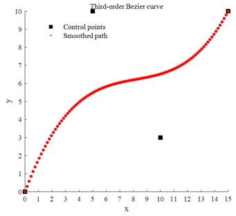
Assuming the control points are , , and , the parameter represents the time variable. The generated Bézier curve point is denoted by , where represents the order of the Bézier point and represents the number of discretized generated points. For adjacent line segments and , two first-order Bézier curve points and are generated using the linear interpolation Eq. (19):
Furthermore, a second-order Bézier point is generated from two first-order Bézier points:
Based on Eq. (19) and Eq. (20), the expression for the second-order Bézier curve is obtained:
According to Eq. (21), for control points , , , …, , the expression of the Bézier curve is:
Fig. 7 illustrates a third-order Bézier curve generated by four control points, where only the first and last control points lie on the curve. In the path planning of the aircraft-TTV system, the intermediate control points indirectly regulate the turning angle and smoothness of the TTV by adjusting the shape and curvature of the path curve, thereby enhancing the stability of the towing trajectory and reducing path fluctuations.
Fig. 7Schematic diagram of Bézier curve optimization
4. Simulation and analysis
To systematically validate the efficacy of the proposed path planning method for the aircraft-TTV system, a systematic simulation verification was conducted by combining the established kinematic model of aircraft-TTV system with the improved path planning algorithm in a typical airport scenario.
4.1. Simulation of towing system path planning algorithm
In APF algorithms, and are the core parameters determining algorithm performance [16] (as shown in Table 2), directly regulating the behavioral characteristics of path planning. In the improved APF, the optimal values of and cannot be directly determined through theoretical derivation and require debugging and optimization based on practical application scenarios. For the specific problem of the aircraft-TTV system addressed in this paper, the parameter settings were selected after debugging as follows: ; .
Table 2Impact analysis of APF algorithm parameters
Parameter | Function description | Too small value | Too large value |
Amplifies destination attraction | Slow convergence, lengthy path | Path oscillation, increased collision risk | |
Enhances obstacle repulsion | Collision risk due to failed obstacle avoidance | Trapped in local minima, excessive path detour |
Fig. 8 presents comparative simulation results between the traditional APF and the improved APF algorithm. As shown in Fig. 8(a), the improved algorithm demonstrates superior performance by maintaining a consistent safety distance from obstacles while successfully navigating to the destination, thereby resolving the unreachable target problem that plagues the traditional approach. Fig. 8(b) reveals that when encountering multiple obstacles, the traditional APF causes the towing system to fall into local minima, resulting in premature stopping near obstacles and failing to reach the intended destination. By contrast, the improved APF effectively avoided obstacles and accurately guided the towing system to successfully arrive at the destination, exhibiting superior path planning capability. To further illustrate the impact of repulsive force direction modification, Fig. 8(c) includes the obstacle repulsion range curves. The traditional APF entered the repulsion range after passing through a narrow channel and collided with the obstacle directly ahead, while the improved APF algorithm detected the obstacle’s position and moved along the tangential direction of its influence domain, successfully avoiding the obstacle and reaching the destination. These comparative results confirm that the improved APF algorithm addresses the shortcomings of the traditional algorithm, unreachable targets and susceptibility to local minima, thereby enhancing the algorithm’s robustness and overall safety.
Fig. 8Comparison of APF before and after improvement
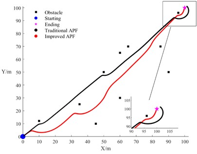
a) Goal reachability comparison
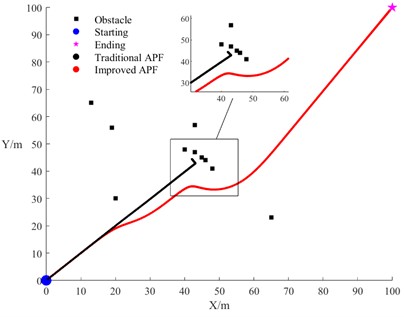
b) Obstacle avoidance comparison
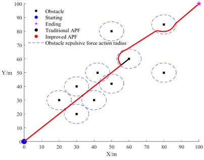
c) Repulsive force direction improvements comparison
4.2. Simulation of aircraft towing vehicle system path planning
The path planning of the aircraft-TTV system primarily faces two critical operational scenarios [1]: right-angle turns and complex obstacle avoidance. Unlike conventional ground vehicles, aircraft-TTV systems exhibit larger dimensions and constrained turning radii. Airport ground environments contain various obstacles such as ground crew, buildings, or ground support vehicles like baggage carts, where traditional manual operations present issues like large visual blind spots and delayed responses. To address these challenges, this study conducts simulations focusing on these two working conditions.
Trade-off between model fidelity and safety assurance while accounting for the overall shape characteristics of the towing system [17], the aircraft is considered as an isosceles triangle, while the towing system is treated as an axisymmetric structure. Specifically: the red rectangle represents the towing vehicle, denoted as A; the blue triangle represents the towed aircraft, denoted as B. The following parameters are defined: maximum towing system speed of 6 km/h; the weight and length of the TTV are 2 t and 5 m, respectively, while the weight and length of the aircraft are 10 t and 22 m, respectively; the maximum acceleration of the TTV is approximately 0.5 m/s2; the TTV maximum angular velocity is 0.26 rad/s. To verify the effectiveness of the proposed method in path planning, comparative simulation analysis was conducted with the improved APF algorithm from reference [10], with simulation results shown in Fig. 9 and Fig. 10.
The specific experimental setup for simulation scenario 1 (right-angle turn condition) are as follows: initial heading angle of the towing system is 90°, starting coordinates of the TTV trajectory are (15, 30), and destination coordinates are (80, 110). Environmental obstacles are modeled as two rectangular areas: obstacle 1 (25 m×10 m) and obstacle 2 (80 m×10 m), with their bottom-left vertex coordinates at (30, 50) and (30, 80) respectively. Comparative results in Fig. 9 show that when the towing system passes through the top-left area of obstacle 2, the trajectory planned by the method in reference [10] maintains too close a distance to the obstacle, presenting obvious collision risks; in contrast, the method in this paper not only ensures a safe distance between the system and obstacles, but also produces smoother and more natural obstacle avoidance paths. When approaching turn areas, the method in this paper achieves gradual adjustment of the heading angle, enabling more stable obstacle avoidance and improving the safety and reliability of path planning.
Fig. 9Simulation diagram of vertical turn path planning
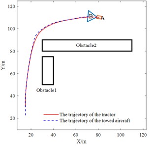
a) Algorithm of this paper
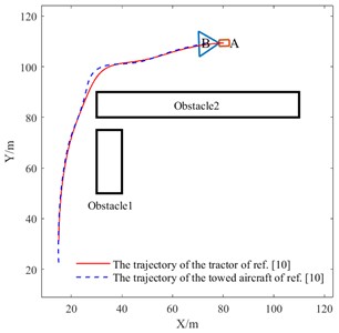
b) Algorithm of ref. [10]
The specific experimental setup for simulation scenario 2 (multi-obstacle condition) is as follows: initial heading angle of the towing system is 45, with starting coordinates at (0, 0) and target point at (90, 90). The environment contains three square obstacles (10 m side length), with their bottom-left corner coordinates at (20, 30), (45, 50), and (85, 55) respectively. The comparative analysis results in Fig. 10 show: When passing through the area of obstacle 1, the trajectory of aircraft B exhibits noticeable oscillations and maintains dangerously close proximity to obstacles, presenting collision risks. In contrast, the improved APF algorithm proposed in this paper not only maintains a safe distance between the towing system and obstacles throughout the entire avoidance process, but also significantly enhances trajectory smoothness and reduces path fluctuations, effectively improving the safety, stability, and economic efficiency of obstacle avoidance.
Fig. 11 presents the variation curves of the TTV’s heading angle and sideslip angle under two working conditions. In the heading angle comparison, the reference method shows significant sudden drops and recoveries during the mid-phase (15-25 s), indicating weaker anti-interference capability, while the proposed method exhibits smoother fluctuations without severe oscillations. By the final experimental phase (25-30 s), the proposed method achieves safe avoidance of obstacle 3 by adopting larger steering angles while maintaining stable approach to the target position. In the sideslip angle comparison, the reference algorithm displays larger amplitude fluctuations during mid-phase, whereas the proposed algorithm demonstrates smaller overall fluctuation amplitudes than the reference method in both conditions, consistently remaining within ±1 with relatively smooth curves, ensuring stable operation of the towing system.
Fig. 10Multi-obstacle path planning
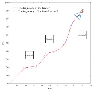
a) Algorithm of this paper
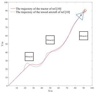
b) Algorithm of ref. [10]
Fig. 11Comparative diagram of simulation parameters
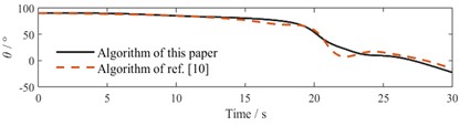
a) Heading angle comparison in Scenario 1
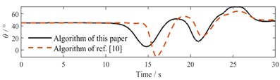
b) Heading angle comparison in Scenario 2
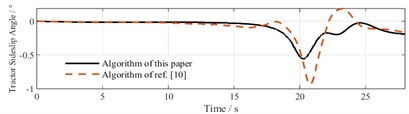
c) Sideslip angle comparison in Scenario 1
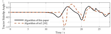
d) Sideslip angle comparison in Scenario 2
The simulation results validate the superior performance of the improved APF algorithm in static obstacle environments. Experimental data conclusively demonstrates that the proposed algorithm achieves coordinated optimization of safety margins and control performance while ensuring real-time capability, providing a technical solution for intelligent ground towing operations at airports.
5. Conclusions
Based on an established mathematical model of aircraft-TTV towbarless system, this study addresses two key limitations of the traditional APF, goal unreachability and local minima, through reconstruction of the potential field function and optimization of dual-component repulsion direction. By incorporating Bézier curve-based path smoothing, the proposed method generates collision-free trajectories that satisfy kinematic constraints. Comparative simulations confirm superior performance: the towing system can safely and stably reach the destination while satisfying positioning and obstacle avoidance requirements in static obstacle environments, thereby improving the reliability of path planning. Future research will extend to 3D dynamic environments to address key technical challenges including multi-obstacle avoidance and cooperative scheduling.
References
-
J. Zhang et al., “Unmanned trajectory tracking strategy for aircraft tug with MPC method,” (in Chinese), Journal of Beijing University of Aeronautics and Astronautics, pp. 1–15, Apr. 2024, https://doi.org/10.13700/j.bh.1001-5965.2023-0431
-
H. B. Du and Q. Q. Zhang, “Statistics and causes analyses of flight accidents,” (in Chinese), Industrial Safety and Environmental Protection, Vol. 42, No. 8, pp. 17–20, Aug. 2016.
-
Y. K. Sun et al., “Review on aircraft towing taxi technologies,” (in Chinese), Journal of Traffic and Transportation Engineering, Vol. 23, No. 3, pp. 23–43, 2023, https://doi.org/10.19818/j.cnki.1671-1637.2023.03.002
-
D. Mandloi, R. Arya, and A. K. Verma, “Unmanned aerial vehicle path planning based on A* algorithm and its variants in 3D environment,” International Journal of System Assurance Engineering and Management, Vol. 12, No. 5, pp. 990–1000, Jul. 2021, https://doi.org/10.1007/s13198-021-01186-9
-
Q. Wu, Y. Su, W. Tan, R. Zhan, J. Liu, and L. Jiang, “UAV path planning trends from 2000 to 2024: A bibliometric analysis and visualization,” Drones, Vol. 9, No. 2, p. 128, Feb. 2025, https://doi.org/10.3390/drones9020128
-
Y. Chu, Q. Chen, and X. Yan, “An overview and comparison of traditional motion planning based on rapidly exploring random trees,” Sensors, Vol. 25, No. 7, p. 2067, Mar. 2025, https://doi.org/10.3390/s25072067
-
N. S. Abu, W. M. Bukhari, M. H. Adli, and A. Ma’Arif, “Optimization of an autonomous mobile robot path planning based on improved genetic algorithms,” Journal of Robotics and Control (JRC), Vol. 4, No. 4, pp. 557–571, Aug. 2023, https://doi.org/10.18196/jrc.v4i4.19306
-
Y. Yang, X. Luo, W. Li, C. Liu, Q. Ye, and P. Liang, “AAPF*: a safer autonomous vehicle path planning algorithm based on the improved A* algorithm and APF algorithm,” Cluster Computing, Vol. 27, No. 8, pp. 11393–11406, May 2024, https://doi.org/10.1007/s10586-024-04287-9
-
K. K. Chai, H. Q. Xu, and J. W. Fan, “DDPG improved artificial potential field method for UAV 3D path planning,” (in Chinese), Electronics Optics and Control, pp. 1–8, May 2025.
-
L. T. Jiang et al., “Obstacle winding strategy of rice transplanter based on optimized artificial potential field method,” (in Chinese), Transactions of the Chinese Society for Agricultural Machinery, Vol. 53, No. S1, pp. 20–27, 2022, https://doi.org/10.6041/j.issn.1000-1298.2022.s1.002
-
T. Guan, Y. Han, M. Kong, S. Wang, D. Feng, and W. Yang, “An improved artificial potential field with RRT star algorithm for autonomous vehicle path planning,” Scientific Reports, Vol. 15, No. 1, pp. 1–21, May 2025, https://doi.org/10.1038/s41598-025-00694-z
-
C. Q. Yang, X. H. Chen, and J. H. Li, “General aviation path planning based on improved artificial potential field method,” (in Chinese), Aeronautical Computing Technique, Vol. 54, No. 2, pp. 37–40, 2024.
-
Z. Wang, M. Hong, and X. W. Liu, “Analysis of handling mode for towing aircrafts and carrier-based tractors in carrier,” (in Chinese), Ship Science and Technology, Vol. 38, No. 17, pp. 140–144, 2016, https://doi.org/10.3404/j.issn.1672-7619.2016.09.029
-
J. H. Bao, X. Zhang, and J. W. Zhang, “A new method of dynamic model building of combination vehicles,” (in Chinese), Journal of Shanghai Jiao Tong University, Vol. 41, No. 2, pp. 244–249, 2007, https://doi.org/10.16183/j.cnki.jsjtu.2007.02.018
-
Y. Yuan, “Research on path planning and navigation control system for towing units,” Chinese Academy of Agricultural Mechanization Sciences, Beijing, China, 2023.
-
C. Xie, T. Tao, and J. Li, “Research on path planning based on improved artificial potential field method,” (in Chinese), Journal of Jilin University, Vol. 41, No. 6, pp. 998–1006, Oct. 2023, https://doi.org/10.19292/j.cnki.jdxxp.20231025.001
-
W. Han et al., “Deck path planning algorithm of carrier-based aircraft based on heuristic and optimal control,” (in Chinese), Systems Engineering and Electronics, Vol. 45, No. 4, pp. 1098–1110, 2023, https://doi.org/10.12305/j.issn.1001-506x.2023.04.18
About this article

This work was supported by the Basic Scientific Research Project of the Liaoning Provincial Department of Education of China (JYTMS20230195).
The datasets generated during and/or analyzed during the current study are available from the corresponding author on reasonable request.
He Ren conceived the original idea and wrote the manuscript. Jiyan Qi finished the extensive editing of English language and style. Xin Zhang supervised the study.
The authors declare that they have no conflict of interest.
