Abstract
A model rocket system serves as an excellent example of a mechatronic system, integrating mechanical, electrical, and control components. Computational Fluid Dynamics (CFD) plays a critical role in mechatronic system design by enabling the analysis and optimization of fluid interactions within these integrated systems. In rocket design, the accurate assessment of aerodynamic forces – thrust, weight, drag, and lift – is essential for optimizing performance. CFD analysis is employed to determine the drag coefficient (Cd) and lift coefficient (Cl), both of which contribute to improving the rocket's aerodynamic efficiency. CFD is a powerful tool for evaluating key aerodynamic parameters such as velocity, pressure, and temperature while also identifying and mitigating design flaws to enhance overall performance. This study examines the model rocket system from a mechatronic system design perspective, evaluating three different mesh structures in two- and three-dimensional CFD simulations to determine the most suitable configuration. The accuracy of the mesh depends on factors such as element size, quality metrics (skewness, orthogonal quality), and first-layer thickness. A well-refined mesh that adheres to these criteria significantly enhances the reliability of the simulation results, ensuring more precise aerodynamic analysis and performance optimization. The analysis results obtained in this study indicate that the rocket’s nose cone and the area around the wings are subjected to the highest forces, and that mechanical and structural improvements are needed in these areas.
1. Introduction
Computational Fluid Dynamics (CFD) is a powerful tool for analyzing fluid behavior across various domains, including aerospace, aviation, energy, and electronics. It provides critical insights into velocity, pressure, and temperature distributions, as well as heat transfer, single- and multiphase flows, and compressible and incompressible fluids. In the field of rocketry, CFD plays a crucial role in evaluating aerodynamic performance, optimizing designs, and improving overall efficiency.
A rocket is subjected to four fundamental forces during flight: thrust, weight, drag, and lift. Among these, drag and lift are aerodynamic forces that significantly influence flight stability and efficiency. The primary objective of CFD analysis in rocket design is to accurately calculate these aerodynamic forces and determine the drag coefficient (Cd) and lift coefficient (Cl). These coefficients are key performance indicators that impact the rocket’s aerodynamic efficiency and flight trajectory. Beyond force and coefficient calculations, CFD analysis also aids in identifying and correcting design flaws. By simulating flow conditions, engineers can detect potential inefficiencies and structural weaknesses, enabling iterative improvements to enhance performance. In this study, a three-dimensional CFD analysis of a model rocket was conducted, evaluating three different mesh structures to determine the most suitable configuration. The meshing process involved creating geometry and flow volume, ensuring the accuracy of numerical simulations. Several critical factors influence mesh quality, including element size, skewness, orthogonal quality, and first-layer thickness. A mesh that optimally satisfies these criteria ensures reliable and precise aerodynamic analysis.
Several previous studies have explored various aspects of model rocket design and performance. As shown in [1] designed a model rocket with a 0.156 m diameter and 2.13 m length, intended to reach an altitude of 3000 meters, using the OpenRocket simulation tool. Their findings highlighted the significance of design and manufacturing in achieving stable flight.
The study in [2] presented presented a two-stage numerical analysis method to improve aerodynamic performance in rocket designs. In the first stage, basic aerodynamic parameters were calculated using OpenRocket software and the Barrowman method, and in the second stage, CFD analyses were performed for different speeds and angles of attack using OpenFOAM. The results showed that the increase in speed and angle of attack negatively affects the lift, moment and drag coefficients, reducing the flight stability and controllability of the rocket. The study contributes to literature by emphasizing the importance of numerical analysis in the design process.
Numerical investigations on the flow performance of a solid-fuel model rocket were conducted for different wing geometries using CAD models created with OpenRocket software. The effects of delta, trapezoidal, clipped delta, arrow delta, and clipped arrow delta wing types on flow-related parameters were analyzed. According to the obtained data, the arrow delta wing model demonstrated the most efficient results, while the notched delta wing design developed based on this model increased speed, acceleration, and altitude, and decreased aerodynamic parameters such as stability and weight. These findings reveal the influence of wing geometry on the flow and show that especially the notched delta wing structure improves the aerodynamic performance of the rocket [3].
In a related study, developed an avionics system incorporating a commercial flight computer for real-time flight monitoring. They also designed a GPS-based recovery system to track and locate rocket components after separation, conducting mechanical endurance tests to validate structural reliability [4].
Aerodynamic performance has been extensively investigated through CFD-based flow analyses. Turbulent flow around a rocket was studied, revealing that drag force primarily occurs at the rear of the fins after the thrust phase ends, with minimal impact on overall flight dynamics [5]. Similarly, aerodynamic conditions necessary for optimal cruise performance were examined using FASTRAN and OpenRocket simulations, showing that the drag coefficient of rocket fins under turbulent conditions can be estimated with an error margin of 1.45 %, and that fin geometry optimization significantly enhances cruise efficiency [6]. Additionally, studies on nose cone design and optimization demonstrated that an aerodynamically optimized nose cone geometry reduces drag force at the leading edge of the rocket, thereby improving overall aerodynamic efficiency [7].
Recent advances in thermal analysis have significantly improved the two-dimensional code G2DHeat by integrating an implicit solution routine and a kinetic model. This enhanced approach enables the simulation of internal decomposition and charring ablation in insulation materials, accounting for gas generation, evolving material properties, and surface erosion. Simulation results, benchmarked against commercial software and experimental data, have shown promising accuracy. Nonetheless, further testing and the implementation of more realistic boundary conditions are recommended to fully validate the model.[8]
A study focusing on the dynamic structural behavior of free-flight missiles addressed the challenge of balancing lightweight design with sufficient rigidity. Both experimental and numerical approaches were employed to analyze a 70 mm caliber missile, emphasizing the importance of understanding the vibration characteristics of flexible aerospace structures. Accelerometers and impact hammer excitation were used to determine the missile’s bending modes, with results confirming frequencies at 134.4, 400.6, 819.4, and 1173.6 Hz. Additionally, a high-fidelity commercial simulation tool validated the experimental findings. The strong correlation between numerical and experimental results underscores the necessity of precise dynamic analysis in optimizing missile flight performance [9].
In a study focused on the validation of computational fluid dynamics (CFD) tools in combustion chamber processes, a collaboration between DLR and Airbus Defense and Space was undertaken within the Propulsion 2020 Project. The research aimed to evaluate CFD modeling accuracy using well-documented test cases. One of the selected test cases, the Penn State chamber (RCM1), was analyzed with three different simulation tools. The study showed that steady-state Reynolds-averaged Navier-Stokes (RANS) approaches were effective in reproducing the measured wall heat flux, a key validation parameter. However, some inconsistencies in the experimental test data were identified, pointing out challenges in achieving precise validation. This research provides important insights into the reliability of CFD models in aerospace propulsion applications [10].
High-amplitude vibrations in large-thrust liquid rocket engines (LREs) pose a significant structural risk, affecting both engine integrity and operational reliability. Studies indicate that gas pulsations and structural vibrations in the combustion chamber are strongly coupled. To analyze this interaction, a 3D dynamic model was developed using the corrugated composite sandwich plate method and validated through operational modal analysis. A novel vibro-acoustic coupling model was proposed, revealing that resonance occurs when the first-order longitudinal acoustic mode interacts with the three-node diameter structural mode. To mitigate this issue, structural modifications were implemented to decouple acoustic and vibration modes, increasing the anti-resonance margin by over 7.5 % and reducing vibration acceleration by two-thirds. These improvements effectively suppressed intense vibrations in the combustion chamber [11].
Although aeroelastic effects are often overlooked in rocket design, they can significantly impact a rocket's performance in real-world applications. A static aeroelastic analysis on a two-stage rocket body was conducted by simulating fluid-structure interactions to evaluate its behavior at different Mach numbers. Aeroelastic effects can lead to deformations in control surfaces due to high aerodynamic forces, negatively affecting stability and maneuverability. Structural deformations may also reduce lift forces on control surfaces, diminishing control effectiveness. Therefore, integrating both static and dynamic aeroelastic analyses into the design process is crucial. In this context, CATIA was used for modeling, ANSYS Workbench for meshing and flow analysis, and FLUENT for flow simulations. Structural analysis was performed by determining the pressure distribution over the rocket body and calculating normal forces. The results provided critical insights into the static aeroelastic response of the rocket body, emphasizing the importance of considering aeroelastic behavior during the design phase to ensure structural integrity [12].
In the literature, the effects of design modifications on the drag force of rocket launchers have been frequently examined. In this context, the study compares the effects of the traditional blunt nose shape with the hemispherical nose shape on the drag force. In the tests conducted, drag values were calculated for different nose shapes and operating conditions using FLUENT CFD software. The study used the M261 Hydra-70 Lightweight Rocket Launcher, a 19-tube, electrically fired 2.75-inch folding fin aircraft rocket (FFAR) as the basis for the investigation. It is common practice to add 15 % to the parasite drag coefficient for external loads, but it was found that reducing this additional value could decrease the drag force. These findings can be considered an important step towards improving the aerodynamic efficiency of rocket launcher designs and support design optimizations aimed at enhancing rocket flight performance [13].
The impact of two parallel boosters attached to the ILR 33 AMBER 2K core rocket stage on its aerodynamic characteristics was investigated through wind tunnel testing. The results showed that the presence of the boosters significantly increased the total drag of the rocket, with the effect varying depending on the Mach number and flight phase. It was also found that the aerodynamic coefficients strongly depend on the location of the boosters relative to the direction of flight deviation. This research clearly demonstrates the effect of parallel boosters on rocket performance, emphasizing how their placement influences aerodynamic efficiency and drag force. The data obtained from the study, validated by CFD simulations, provides valuable insight for accelerating future rocket designs and reducing development costs. In this context, the combined use of CFD and wind tunnel testing is shown to increase efficiency in aerodynamic analysis and rocket design [14].
Rocket fins play a crucial role in ensuring the rocket’s stability, but they also create undesirable effects such as drag, primarily caused by skin friction and pressure drag. The study in [15] analyzes the total fin drag analyzes the total fin drag of low-altitude rockets with various fin configurations, using mathematical prediction and Computational Fluid Dynamics (CFD) methods. The findings show that drag increases approximately linearly with the fin’s semispan, while the effect of fin thickness is comparatively smaller, particularly for shorter fins. The study empirically correlates fin drag with both semispan and thickness. Additionally, it was found that despite noticeable discrepancies in the drag magnitudes predicted by both approaches, the OpenRocket software predicts the trend well, with a highest root mean squared error (RMSE) of only 0.3 %. This demonstrates that it is now possible to correct OpenRocket data to more accurate values without the need for Computational Fluid Dynamics analysis.
The application of CFD and CSD methods has been employed to address the static aeroelastic problems of slender rockets. To ensure accurate prediction of static deformations and aerodynamic characteristics, two-way coupling and inertia relief approaches were utilized. Initially, aerodynamic coefficients for the rigid rocket were calculated and validated against experimental data. The results revealed significant differences between the aerodynamic behavior of the deformed and rigid rockets. As the flight angle of attack increases, greater deformation occurs, which leads to reductions in both drag and lift force coefficients, a forward shift in the center of pressure, and a decrease in overall rocket stability. These variations can have a direct impact on the flight trajectory and stability of the rocket [16].
The numerical simulation of the static aeroelastic behavior of a simple guided rocket equipped with a duck rudder actuator has been conducted using inertia relief and CFD/CSD two-way coupling methods. The impact of the duck rudder on aerodynamic characteristics and flexible deformation has been thoroughly analyzed. Initially, the CFD method based on the SST - turbulence model was employed to calculate parameters such as lift force, drag force, and yaw moment coefficients. When compared with experimental data, the error remained below 10 %, confirming the reliability of the fluid dynamics simulation approach.
By integrating CFD-based aerodynamic analysis into the design of model rocket systems from a mechatronic perspective, the research aims to enhance aerodynamic efficiency through advanced simulation techniques and optimized mesh structures, ultimately contributing to improved flight performance and structural reliability [17].
2. VDI 2206 of model rocket mechatronic system design
VDI 2206 is a German engineering guideline that provides a structured framework for mechatronic system design, emphasizing an iterative and interdisciplinary approach. It integrates mechanical, electrical, and software engineering into a unified development process, ensuring systematic design and validation. The model follows a V-Diagram structure, where system requirements and conceptual designs on the left side are progressively refined, while the right side focuses on verification and validation through simulations, prototyping, and testing. This approach is widely applied in robotics, automotive, aerospace, and industrial automation.
The basic steps of applying the VDI2206 V-Diagram to model rocket system design are shown in Fig. 1.
Requirement: The basic mission definition and objectives of the project will be determined at this stage. Requirements such as the rocket reaching an altitude of 1500 meters, dropping payload at this altitude and then landing safely by deploying its parachutes with the recovery mechanism are detailed. In addition, important parameters to be considered in the CFD analysis, such as velocity, pressure distribution and aerodynamic forces, are also defined. These requirements guide both the design process and the analysis and testing phases.
Features: The technical details of the rocket are determined at this stage. Design parameters such as the length and diameter of the body, the type of material used, and surface roughness are clarified. The boundary conditions required for CFD analysis and the type of fluid to be considered in the analysis, air, are defined. These properties are the basic data that guide the design of the rocket and support analytical evaluations. Clearly defined specifications provide the basis for verification and conformity checks in the later stages of the project.
Fig. 1VDI 2206 V-diagram of mechatronic system design
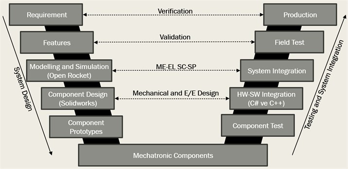
Modelling and Simulation: The mechanical design of the rocket is first prepared with simulations using the Open Rocket application and a two-dimensional draft design is obtained. Then, the final design will be created as a three-dimensional CAD model in SolidWorks software. The aerodynamic behavior of the rocket is investigated using ANSYS Fluent for CFD analysis. At this stage, the mesh structure is carefully created and the analysis parameters such as Mach number and Reynolds number are determined. Simulations are carried out to understand the temperature, drag forces and pressure distribution of the rocket under the airflow during flight.
Component Design: The subcomponents of the rocket are designed in accordance with the requirements of the project. Parts such as the fuselage, payload bay, engine and fins are detailed and optimized to increase aerodynamic performance. The dimensions determined through the Open Rocket application are finalized by modelling in SolidWorks. The components of the rocket are evaluated for both structural strength and flight stability. The physical system with the mechanical subsystem, material selection, and electrical-electronic subsystem were also evaluated carefully.
Component Prototypes: In order to validate the design, prototypes of the rocket's components are produced. In this process, 3D printers and CNC machines are used for the production of prototypes. The prototypes are used to identify the shortcomings of the design and then the necessary adjustments are made for the final design. Prototype testing is an important step to evaluate the functionality and performance of components.
Mechatronic Components: The rocket's recovery mechanism, sensors and electronic control circuits are designed and integrated at this stage. The parachute deployment mechanism is tested numerous times outside the rocket body. The design and integration of these components is optimized to ensure safe landing of the rocket.
Component Test: Each component is tested individually to verify its functionality. Elements such as the recovery system, engine performance and the efficiency of aerodynamic surfaces are evaluated at this stage. Component tests ensure that the design can be successfully implemented. This phase is characterized by component prototypes.
Hardware-Software Integration (HW-SW Integration): The ground station software for processing the data collected by the rocket during flight is developed using C#. The embedded system software is coded in C++ and the microprocessor is integrated with the recovery mechanism. Hardware and software integration is a vital stage for the rocket to fulfil all missions
Mechanical and Electrical/Electronic Subsystem Design: In this phase, the focus is on the integration of the mechanical and electrical/electronic (E/E) systems of the rocket. While the design of mechanical components such as the body structure, fins and parachute deployment mechanism are detailed, electrical/electronic components such as sensors, batteries and control circuits are designed and optimized. The compatibility between the mechanical system and the electronic system is checked. In this process, hardware-software (HW-SW) integration is realized, and the mechanical components are coordinated with the electronic control systems. In particular, the integration of the recovery mechanism with the microcontroller is verified and tests are performed at both software and hardware levels. This stage is a critical step to ensure the systematic operation of the rocket and to prevent possible errors.
System Integration: All components of the rocket are assembled and tested as an integrated system. ANSYS simulation results are compared with physical prototype test results. This integration is performed to verify whether the system meets the design requirements.
Mechanical, Electronic, Software Subsystems (ME-EL-SC-SP): Mechanical, electronic and software processes are integrated to ensure that all systems of the rocket work in harmony. CFD analysis results guide the design of electronic control systems. Software simulations are prepared in accordance with the performance requirements that the rocket will encounter during flight.
Field Test: The mechatronic systems of the rocket are evaluated in a test environment that simulates real flight conditions. During these tests, critical functions such as the opening of the parachute at the right time, the functionality of the payload release mechanism and the safe landing of the rocket are verified. Instead of high-cost real flight tests, simulation methods that can provide similar results were preferred. This method saves time and reduces costs, while providing a comprehensive assessment of the reliability of all rocket systems.
Validation: At this stage, the data obtained during the field tests of the rocket are analyzed to assess whether the rocket meets the requirements set in the specifications phase. It is confirmed that the basic system requirements such as the rocket reaching an altitude of 1500 meters, correct operation of the payload release mechanism and safe landing are met.
The performance determined during the field tests is compared with the design targets and analyzed for compliance with real flight and landing scenarios. If deviations from the targets are detected, necessary revisions are made to the design. This process is a critical step to ensure that the rocket fulfils all its functions completely.
Production: At this stage, material selection and production methods are optimized according to the project objectives. The components of the rocket are manufactured or procured in accordance with the design requirements. After quality controls, all components are assembled and mechanical, electronic and software compatibility is checked. Production ensures that the results of design and analysis are transformed into physical products and the rocket is ready for flight. This stage is critical for the success of the project.
Verification: At this stage, the compliance of the project with the technical requirements specified in the specifications is checked in detail. The performance of the rocket is compared with the targets defined in the requirements phase. The CFD analysis results are compared with the data obtained from field tests to assess the suitability and functionality of the aerodynamic design. Thanks to these comparisons, it is determined whether the design and production processes of the rocket have been successfully completed. In cases where the requirements are not met, necessary corrections are made in the design and production stages. This process plays a critical role in ensuring that all systems of the rocket are operating in accordance with expectations.
3. Subsystems of the model rocket mechatronic system
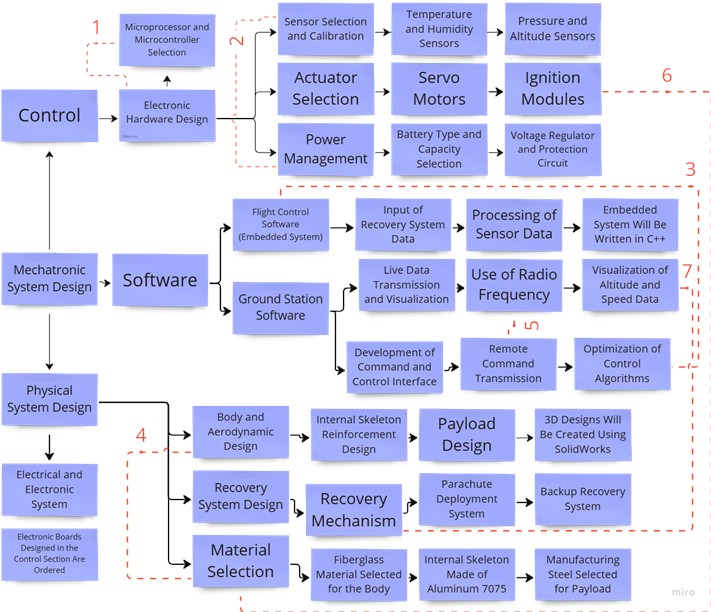
Fig. 2 shows a diagram of the subsystems of the model rocket system. All of the details which are given using the number (1-7) in red color in Fig. 2 are elaborated in the following sentences. (1) Microprocessors and microcontrollers are the basic components of electronic hardware design. The design of this hardware is shaped by the input-output needs and performance requirements of the microcontroller. Microcontrollers process data from sensors and control actuators. They also provide the necessary processing power for the flight control software to operate. (2) A stable power supply is required for correct and reliable operation of the sensors. Power management regulates and provides the energy required by the sensors. Resistance to environmental conditions such as temperature, pressure and humidity plays an important role in sensor selection. Power management supports long-term operation of sensors through battery selection, voltage regulation and energy efficiency. (3) Flight control software includes control algorithms to stabilize the rocket and keep it on the targeted trajectory. These algorithms prevent unnecessary energy consumption during the guidance of the rocket and increase the reliability of the system. The correct and efficient operation of the software is achieved by optimizing the control algorithms. (4) The design of the rocket body depends on the type of material used. The choice of material directly affects both aerodynamic performance and structural strength. While materials such as fiberglass provide lightness and durability in aerodynamic design, materials such as aluminum used in the internal skeleton offer a combination of structural strength and lightness. (5) Radio frequency enables remote data and command exchange between the ground station and the rocket. This system is a critical communication protocol for guiding the rocket during flight and intervening when necessary. Radio frequency increases the flight safety and controllability of the rocket. (6) Ignition modules must be designed to withstand high temperature and pressure conditions. These modules are manufactured from highly durable and heat-resistant materials. The body material is also selected to be compatible with the ignition systems, thus ensuring structural integrity. (7) The triggering of the recovery mechanism depends on the analysis of the velocity and altitude data received from the rocket. These data ensure that the recovery mechanism is activated at the right time. By visualizing the relevant data, both reliability is increased, and the success rate of the recovery process is increased.
Fig. 2Subsystems of the model rocket mechatronic system
2D and 3D flow analyses were performed on a model rocket geometry. The formulas used for the calculation of drag and lift coefficients while solving the network structures created in these flow analyses are given in Eq. (1) and Eq. (2):
where – drag force; – lift force; – drag coefficient; – lift coefficient; – reference area; – density of the fluid; – flow velocity relative to the object.
4. Flow analyses for the model rocket
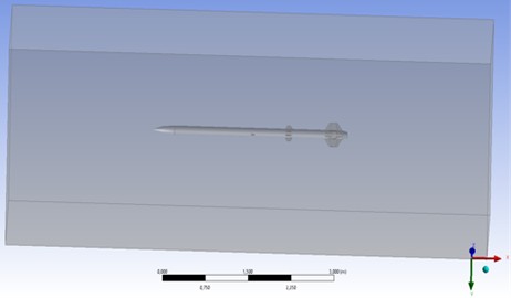
As shown in Fig. 3, the 3D rocket design completed in SolidWorks was transferred to Ansys Workbench as a geometry within the fluid (air mass) in contact with it.
Fig. 3Geometry preparation (CAD) and flow volume generation
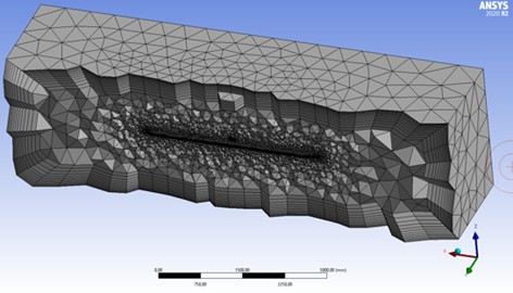
After the name assignment (inlet, outlet, body and wall), the mesh creation part, which is the most important stage in terms of accuracy and reliability of the analysis shown in Fig. 4, was started. The mesh was created by considering the mesh criteria. These criteria are element size, quality values (skewness and orthogonal quality) and the number of nodes and elements that affect the solution time of the mesh.
Skewness and orthogonal quality values were checked for conformity. It was found to be suitable. The element size for the first mesh was assigned as 250 mm. Orthogonal quality and skewness values were found to be 0.74669 and 0.25138 respectively. The number of discarded meshes is 94789. The quality values for the second mesh were 25 mm for the element size criterion and 10 mm for the first layer thickness criterion. A mesh was created by entering an input and as a result of the mesh, the skewness value was found to be 0.19868 and the orthogonal quality value was found to be 0.80033. Although these values are very good, since the number of elements is over 3 million, the program will solve this mesh in more than 15 hours.
A 15-hour analysis would be difficult to intervene in and would prolong the testing process significantly. Furthermore, one of the key objectives was to obtain the analysis with the best possible values in the shortest possible time, so this model was not chosen. This mesh was not solved, and another mesh was tried instead.
For the new tested mesh, the first layer thickness was chosen as 2,5 mm and the element size as 250 mm again. As a result of the mesh assignments, the number of nodes, number of elements and quality values of all meshes were compared and it was decided that the third analysis was the most appropriate analysis. For the third and last mesh tested, the skewness value was 0.27629 and the orthogonal quality value was 0.72159. Continued with the solution settings.
After the mesh assignment and naming were completed, variables such as input-output parameters, methods to be used, turbulence parameters were determined in the setup tab. In the setup section, the solution was started by taking the solution based on pressure and activating the energy. Then the viscous model was determined as SST k-omega.
Fig. 4Mesh assignment
The analysis was solved as pressure based. The reason for this is that air is considered compressible at high speeds and air is defined as the ideal gas when selecting the parameters. Considering all these factors, since it is not reasonable to perform density-based analysis, pressure-based analysis, which gives more accurate results at high temperatures, was preferred.
By activating the energy icon, it is aimed to observe the changes of parameters such as temperature and pressure on the rocket. Turbulence modelling is also one of the important stages. It is the creation and use of a mathematical model to predict the effects of turbulence. Based on sources and articles, SST k-omega, which is the most preferred model in rocket analyses and recommended for supersonic speeds, was chosen as the turbulence model. This turbulence model is solved by means of two-process mathematical equations and gives the most accurate results that can be achieved with these solution functions.
Viscosity is the resistance of a fluid to deformation due to surface tension. It can also be defined as the fluid's internal resistance to flow. Except for superfluid, all real fluids show resistance to surface tension. On the other hand, a fluid that shows no resistance to surface tension is called an ‘ideal fluid’.
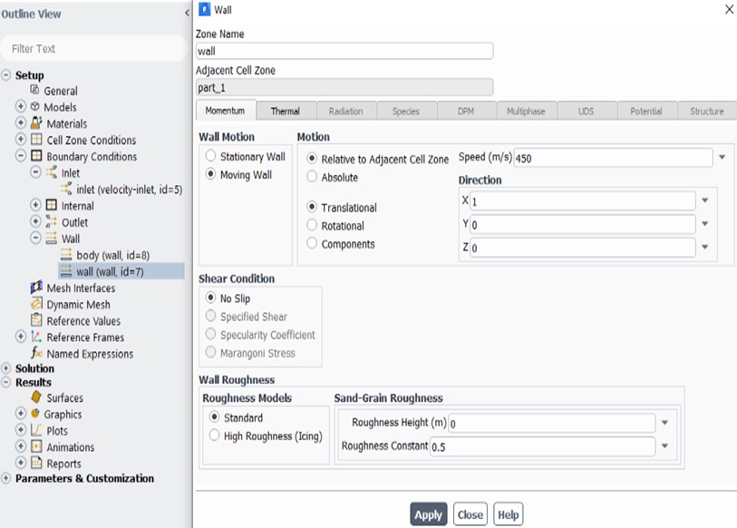
The Sutherland formula is an approximation that the viscosity of gases depends on temperature. In this analysis, Sutherland is activated to calculate the variation of the viscosity of the flow with temperature. Wall velocity, i.e. linear velocity, is entered as 450 m/s. Moving Wall and No Slip Concepts were encountered while entering the wall velocity. Of these concepts, moving wall means that the velocity gradient (slope) from the wall to the free flow velocity is not zero and is used for a moving surface. No slip can be conceptually summarized as assuming that the velocity of the fluid relative to the boundary will be zero at a solid boundary. Some of the adjustments made are shown in Fig. 5.
The area value was assigned by calculating the vertical cross-sectional area of the rocket. The length value was assigned by checking via SolidWorks. The temperature and velocity values were also determined in accordance with the maximum values reached by the rocket. These values are 0.0153938 m2, 3.3828 m, 300 K and 450 m/s respectively. In order to obtain graphs of the desired values (drag and lift coefficients, moment and moment coefficient), the necessary assignments were made from report definitions. Standard initialization was selected from the initialization methods and the speed in the x direction was entered as 450 m/s. Finally, the number of iterations was set to 500 in the Setup section, convergence was switched off in order to prevent small errors that may occur in the analysis and the running process was started. In addition to all these, the same conditions were provided for the two-dimensional rocket geometry, making it suitable for analysis and the analysis was solved.
Fig. 5Setup settings (Wall speed)
The changes of the coefficients and forces defined in the report definitions section during the solution settings were obtained as graphs depending on the number of iterations as a result of the running process. Since the results of these iterations started to converge after a certain point, the graphs started to become a straight line after that iteration value. After all graphs were taken and interpreted and the solution part was completed, the ‘Results’ tab was opened, and the final results of the analysis were taken. The value ranges entered for each parameter for these results are 0-466 m/s for speed, 0-100 °C for temperature, 0-100 kPa for pressure, and 0-5 kg/m3 for density. Depending on these values, the result images of two- and three-dimensional rockets are as follows.
Fig. 6Results for velocity parameters: a) velocity parameter results for 2D rocket geometry; b) velocity parameter results for 3D rocket geometry
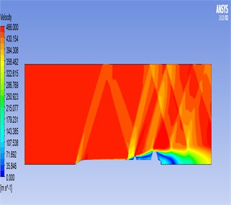
a)
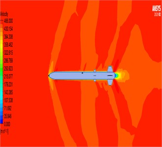
b)
Fig. 7Results for the temperature parameter: a) temperature parameter results for 2D rocket geometry, b) temperature parameter results for 3D rocket geometry
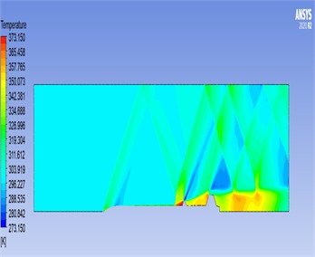
a)
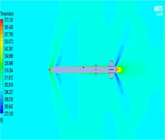
b)
Fig. 8Results obtained for the pressure parameter: a) pressure parameter results for 2D rocket geometry; b) pressure parameter results for 3D rocket geometry
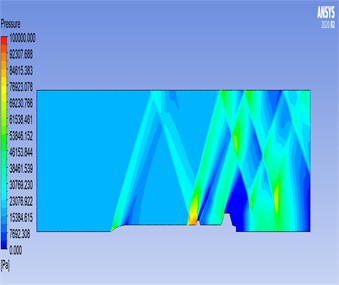
a)
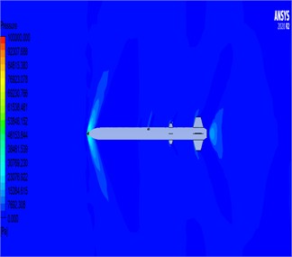
b)
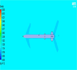
Fig. 9Results obtained for the density parameter: a) density parameter results for 2D rocket geometry; b) density parameter results for 3D rocket geometry
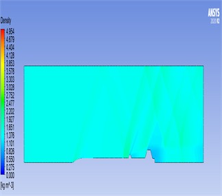
a)
b)
5. Conclusions
This study examined the VDI 2206 mechatronics system design approach for model rocket mechatronic system design with a structured, interdisciplinary approach to improving the efficiency and durability of the rocket. The V-diagram methodology was applied to systematically refine geometry, material selection, and aerodynamic properties through iterative CFD simulations and validation processes. Design modifications aimed at reducing aerodynamic drag, optimizing lift characteristics, and enhancing structural resilience were implemented, aligning with the systematic development, integration, and validation principles of VDI 2206.
We examined the aerodynamic behavior of a model rocket system using Computational Fluid Dynamics (CFD), with a focus on pressure-based analysis. The results indicate that density variations were minimal and did not significantly affect the flow dynamics, confirming that density is not a critical parameter in this context. The most significant aerodynamic effects occurred around the nose cone and fins. Specifically, as shown in Fig. 6(a-b), the velocity around the nose cone was observed to average approximately 350 m/s, highlighting the high-speed airflow impact at this leading structure. Temperature measurements revealed values around 53 °C near the nose cone and fin areas, while temperatures rose to between 92 °C and 100 °C near the rocket motor exit region, indicating thermal gradients linked to propulsion effects. The results can be seen in Fig. 7(a-b).
Pressure distributions were most pronounced over the fins, with an average pressure of approximately 92,307 Pa, emphasizing the aerodynamic load these structures bear during flight. These components play a critical role in the rocket’s performance, as the nose cone is the first structure to encounter airflow, and the fins contribute to stability by interacting with aerodynamic forces. Variations in temperature, velocity, and pressure predominantly affect these regions, emphasizing the need for targeted design optimization to enhance performance and structural integrity. The results based on the pressure parameter are shown in Fig. 8(a-b).
The findings demonstrate that targeted design optimizations of the nose cone and fin geometries can significantly enhance the cruise performance of the rocket. Through a holistic mechatronic design approach, integrating mechanical structures, aerodynamic simulations, and control system considerations, this research contributes to the advancement of model rocket systems, ensuring improved efficiency, stability, and reliability. According to the findings of this study, the nose cone and winglet geometries of the model rocket are most exposed to force and require optimisation for better flight performance. Based on these analysis results, mechanical improvements have been made to increase the strength of the relevant parts of the model rocket.
References
-
F. Çetin, B. Demirkan, A. Kıvrak, and T. Unler, “Fueled model rocket design and flight simulation,” (in Turkish), in Proceedings of the 3rd International Conference on Applied Engineering and Natural Sciences, 2022.
-
A. F. Ozkan, “Numerical investigation of the effect of aerodynamic characteristics of a subsonic rocket on flight simulation,” (in Turkish), 2025.
-
C. Özel, C. K. Macit, and M. Özel, “Investigation of the effects of new type notched delta wing model on the flight performance of the rocket,” (in Turkish), Fırat Üniversitesi Mühendislik Bilimleri Dergisi, Vol. 35, No. 1, pp. 175–193, Mar. 2023, https://doi.org/10.35234/fumbd.1183692
-
H. H. Bilgic, S. Çoban, and A. Yapıcı, “Designing, modeling and simulation of solid fuel rocket ALP-01,” European Journal of Science and Technology, Vol. 15, pp. 511–518, Mar. 2019, https://doi.org/10.31590/ejosat.540884
-
F. Şimşek and S. B. Babayigit, “High-altitude model rocket design: flow analysis and optimization to reach 3000 meters,” (in Turkish), Osmaniye Korkut Ata University Journal of the Institute of Science, Vol. 6, No. 2, 2023.
-
A. Datye, “Fin optimization for enhanced flight performance of an experimental rocket,” in Proceedings of the National Conference on Undergraduate Research, 2018.
-
K. Foster et al., “Design and integration of a high-powered model rocket – I,” in AIAA Scitech 2020 Forum, Jan. 2020, https://doi.org/10.2514/6.2020-0145
-
J. A. K. Riise, “Computer code for thermal analysis of rocket motors,” Institute for Energi-Og Prosessteknikk, 2008.
-
M. A. Habaka, S. Farag, M. Khalil, and M. Y. Ahmed, “Experimental and computational dynamic structural analysis of free-flight rockets,” in IOP Conference Series: Materials Science and Engineering, Vol. 973, No. 1, p. 012021, Nov. 2020, https://doi.org/10.1088/1757-899x/973/1/012021
-
B. Ivancic, H. Riedmann, M. Frey, O. Knab, S. Karl, and K. Hannemann, “Investigation of different modeling approaches for computational fluid dynamics simulation of high-pressure rocket combustors,” Progress in Propulsion Physics, Vol. 8, pp. 95–116, Jul. 2016, https://doi.org/10.1051/eucass/201608095
-
D. Du, E. He, D. Huang, and G. Wang, “Intense vibration mechanism analysis and vibration control technology for the combustion chamber of a liquid rocket engine,” Journal of Sound and Vibration, Vol. 437, pp. 53–67, Dec. 2018, https://doi.org/10.1016/j.jsv.2018.08.023
-
K. Kiran and E. R. Cholleti, “Static aeroelastic analysis on two stage rocket body,” International Journal of Engineering Research and, Vol. V4, No. 11, pp. 388–395, Nov. 2015, https://doi.org/10.17577/ijertv4is110423
-
E. A. S. Bhui, “Aerodynamic design of rocket launchers to reduce drag,” International Journal of Engineering Research and Technology (IJERT), Vol. 26, No. 3, pp. 224–227, 2012.
-
A. Krzysiak, D. Cieśliński, R. Placek, and P. Kekus, “Experimental study of the boosters impact on the rocket aerodynamic characteristics,” Aircraft Engineering and Aerospace Technology, Vol. 95, No. 2, pp. 193–200, Jan. 2023, https://doi.org/10.1108/aeat-01-2022-0025
-
A. A. Adnan, A. H. A. Hamid, Z. Salleh, and M. Z. Azizi, “Mathematical and computational fluid dynamics analysis of low-altitude rocket drag for various fin configurations,” Journal of Aeronautics, Astronautics and Aviation, Vol. 56, No. 3, pp. 781–790, 2024.
-
L. K. Abbas, D. Chen, and X. Rui, “Numerical calculation of effect of elastic deformation on aerodynamic characteristics of a rocket,” International Journal of Aerospace Engineering, Vol. 2014, pp. 1–11, Jan. 2014, https://doi.org/10.1155/2014/478534
-
H. Chen and D. Chen, “Numerical simulation calculation and analysis of the effect of rocket and duck rudder on its aerodynamic characteristics and flexible deformation,” in IOP Conference Series: Materials Science and Engineering, Vol. 677, No. 5, p. 052051, Dec. 2019, https://doi.org/10.1088/1757-899x/677/5/052051
About this article

The authors have not disclosed any funding.
The datasets generated during and/or analyzed during the current study are available from the corresponding author on reasonable request.
Yağmur Ak: Conceptualization, experimental work, writing-review and editing. Efekan Koç: experimental work, writing-review and editing. Savaş Dilibal: writing-review and editing, supervision, and validation.
The authors declare that they have no conflict of interest.
