Abstract
This study proposes a novel dual-stator linear-rotary ultrasonic motor. The piezoelectric ceramic excites both out-of-plane and in-plane vibration modes within the stator. These distinct vibration modes independently drive the slider (rotor), generating reciprocating linear and rotational motions, respectively. Finite element analysis and laser vibrometer-based vibration testing validated the motor's operational principle. The close agreement between simulated and measured resonant frequencies for both vibration modes, with mere discrepancies of 3 % and 4 %, respectively, underscores the accuracy of the stator’s vibrational characteristics. Subsequently, two stators are fabricated and assembled to the ultrasonic motor prototype. Experimental results demonstrate the motor’s impressive performance, achieving a maximum linear velocity of 265 mm/s and a peak rotational speed of 1600 rpm. Furthermore, the motor delivers a maximum thrust force of 0.18 N and a stalling torque of 1.8 mN·m.
Highlights
- The dual-stator 2-DOF linear-rotary ultrasonic motor achieves both linear and rotary motions through distinct operating modes of its driving feet.
- The 2-DOF linear-rotary ultrasonic motor can achieve both linear and rotary motion using only a single electrical signal.
- The preload between stator and brass tube can be adjusted by varying the size of the brass tube slit
1. Introduction
According to the number of degrees of freedom of motion, ultrasonic motors can be divided into single-DOF and multiple-DOF motors [1-3]. Single-DOF ultrasonic motors mainly include rotary and linear types. They have been successfully used in various fields, such as aerospace exploration [4], medical devices [5, 6], camera autofocus mechanisms [7-9] and other applications [10,11]. Among these, the most widely used and extensively researched single-DOF ultrasonic motors are the traveling wave ultrasonic motor (TWUSM) [12-16] and standing wave ultrasonic motors [17,18]. In addition, a linear ultrasonic motor (LUSM) can achieve linear motion by utilizing two separate vibration sources with a phase difference on the stator or by superimposing two vibrations from a single vibration source [19-23]. Compared to the research on single-DOF ultrasonic motors, only a few researches focus on the multi-DOF ultrasonic motors. In the past, most multi-DOF ultrasonic motors employed spherical rotors to generate rotational motion in various directions [24-29]. However, the urgent demand for extreme thinness and compact structure in devices such as smartphones, drones, and endoscopes requires the next generation of actuators to not only further reduce their size but also integrate multi-functional drive capabilities. Typical applications include: zoom lenses requiring rotational movement to switch lens positions or optical paths, endoscopes requiring rotational scanning to expand the field of view, and drone gimbals requiring coordinated translation and rotation to achieve multi-axis stabilization. These scenarios urgently require the simultaneous generation of effective linear thrust and controllable rotational movement within a single miniaturized structure.
Li et al. proposed a high-thrust screw-type piezoelectric ultrasonic motor capable of achieving rotary-linear motion using a three-wavelength excitation mode [30]. However, it cannot achieve independent rotation or linear movement due to the threaded connection. Wang et al. proposed a rotary-percussive ultrasonic drill as an effective tool for subsurface penetration in minor planet exploration despite its complex structure [31]. Ceponis et al. proposed a novel piezoelectric actuator that generates elliptical motion trajectories in an orthogonal plane through a double elliptical frame structure and harmonic excitation with a phase difference of /2, enabling independent control of the linear and rotational motion of a cylindrical slider-rotor [30]. Han et al. proposed a compact two-degree-of-freedom impact-type linear-rotary motor based on a single piezoelectric ceramic, with spiral fork electrodes designed on its outer surface [32]. Independent linear motion is achieved through in-phase drive voltage signals, while independent rotary motion is achieved through out-of-phase duty cycle signals. However, it is difficult to achieve completely separated linear or rotary motion in the ultrasonic frequency range. Wang et al. designed a linear-rotary ultrasonic motor based on a bonded-type transducer that combines the longitudinal-bending (L-B) and orthogonal-bending (B-B) modes [33]. This design was inspired by the principles of biomimicry, specifically the movement of earthworms and was intended for optical focusing. Their 2-DOF USM was composed of 16 PZT plates and one metal substrate and the overall structure was relatively complex. The above work is limited in its application design due to the increased size and complex drive signal design caused by the structure of the piezoelectric motor stator. In addition, ultrasonic motors with single signal excitation can usually only complete one degree of freedom of motion and do not have the ability to complete both linear and rotational motion [34-38]. Therefore, it is necessary to design a linear-rotary ultrasonic motor with a compact structure and a simple excitation strategy.
A dual-stator 2-DOF linear-rotary ultrasonic motor is presented in this work. Unlike previous ultrasonic motors, the motor requires only a single-phase electrical signal to achieve linear-rotary motion.
At first, the structure of the proposed motor is designed. Then, the operating principles of the motor are described. Finite element methods are used to calculate the vibration modes and the corresponding resonant frequency of the stator. Then, the prototype motor is fabricated and the vibration modes of the stator are tested using a laser Doppler scanning vibrometer system. Additionally, the output characteristics of the linear-rotary ultrasonic motor are tested and analyzed in detail. Finally, several conclusions are drawn.
2. Configuration and operating principle
2.1. Construction design
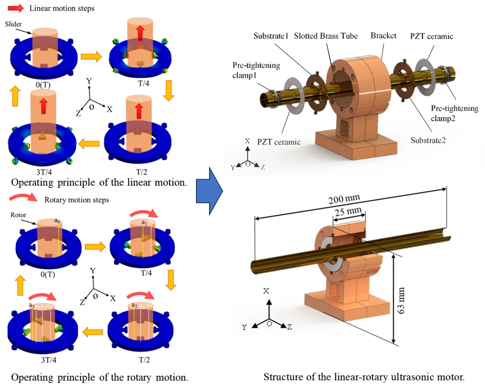
As shown in Fig. 1, the dual-stator 2-DOF linear-rotary ultrasonic motor consists of two stators bonded with a piece of PZT ceramics, a slotted brass tube, two pre-tightening clamps and a bracket. The selected PZT ceramics are annular piezoelectric ceramics without zonal polarization. The stator 1 and stator 2 which have the same structural dimensions are fixed on the symmetrical sides of the bracket, respectively. The size of the two stators is Φ25 mm × 1.5 mm. The slotted brass tube, which serves as both the motor’s rotor and the slider, passes through the centers of stators 1 and 2 in sequence as shown in Fig. 2(a). The double stator design plays two roles. Firstly, it simplifies the slider (rotor) installation by eliminating the inclusion of the bearings or other fixing mechanisms. Secondly, it not only enhances motor output performance but also enables the reciprocating linear motion of the slider (rotor).
The slotted brass tube is a thin hollow cylinder with a slit design and its outer diameter is slightly larger than the diameter of the stator. The slit width of the slit brass tube is 0.5 mm. The dimensions of the brass tube are Φ10 mm × 200 mm. The thickness of the brass tube is 0.2 mm. Two pre-tightening clamps are installed at both ends of the brass tube to adjust the size of the brass tube slit, thereby achieving the adjustment of the preload between the stators and the brass tube. Fig. 2(b) illustrates that the preload between stator and brass tube can be adjusted by varying the size of the brass tube slit. Afterwards, the slotted brass tube is inserted directly into the center of the stators and the applied force is removed to create a preload on the stator and slotted brass tube. Therefore, the preload is mainly adjusted by the opening size of the slotted brass tube. Lastly, the bracket which works as an experimental support structure is made by the 3D printing (K1, CREALITY, China) method wherein the polylactide (PLA) is used as the printing material. The overall dimensions of the bracket are approximately 63 mm × 25 mm ×40 mm.
Fig. 1Structure of the linear-rotary ultrasonic motor
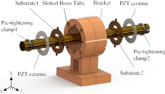
Fig. 2a) Overall size parameters of the motor; b) the preload boundary condition
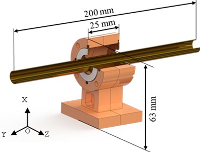
a)
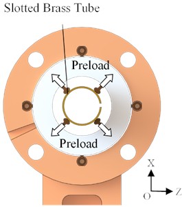
b)
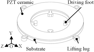
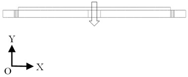
The structural details of the stator are shown in Fig. 3(a). The stator consists of one substrate, four lifting lugs, four driving feet and one piece of PZT ceramic. The outer diameter, inner diameter and thickness of the ring are 25 mm, 15 mm and 1.2 mm, respectively. The edge of the driving feet has been rounded to reduce the impact of the slit on the motor velocity. The inner ring surface of the four driving feet is 10 mm, which is used to drive the brass tube for linear and rotary motion. One piece of PZT ceramic is bonded to the surface of the ring and its polarization direction is shown in Fig. 3(b). The PZT ceramic is annular piezoelectric ceramic without zonal polarization.
2.2. Operating principle
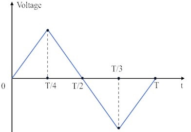
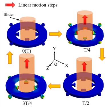
The ultrasonic motor belongs to a standing wave motor while its working principle is similar to that of an inertial motor, so the sawtooth wave signal is chosen as the motor excitation signal [39-41]. The linear motion of the motor is achieved by utilizing the principle of inertia displacement and capitalizing on the differences between static and kinetic friction forces at the contact surface between the stator and the slider [42]. Fig. 4 (b) illustrates the operating principle of the motor's linear motion during one cycle under the excitation of a sawtooth signal (Fig. 4(b)).
Fig. 3The stator’s structure: a) the structure of the stator; b) polarization direction of the PZT ceramic
a)
b)
This process can be divided into the following four steps:
Step 1 (0→T/4): The driving feet vibrate in an out-of-plane bending mode to push the slider and accelerate it forward. The slider starts to slide in the direction.
Step 2 (T/4→T/2): Next, the driving feet return to their original position and the slider begins to decelerate while it still slides in the direction.
Step 3 (T/2→3T/4): The driving feet vibrate in the opposite direction, causing the slider to slide forward until it stops due to the inertial force.
Step 4 (3T/4→T): The driving feet return to their original position along the direction and the slider accelerates once again.
Fig. 4a) The sawtooth signal; b) operating principle of the linear motion
a)
b)
Upon the next excitation signal being applied, a similar motion as that in step 1 would occur. That is the driving feet bend longitudinally to push the slider and accelerate it forward. Such a reciprocating cycle drives the slider to move continuously in a straight line. Similarly, the forward and reverse linear motion of the rotor can be achieved by applying excitation signals to the two stators at different times.
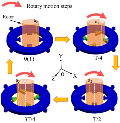
The rotary motion of the motor is achieved by driving the in-plane bending mode of the driving feet. The working principle of this motor is similar to that of a piezoelectric inertia motor. Although the stator is a symmetrical structure, the slotted structure of the rotor causes the rotor to be an elliptical tube, resulting in asymmetry in the structure between the drive feet and the rotor, which can only achieve unidirectional rotation [43, 44]. Fig. 5 illustrates the operating principle of rotary motion by depicting four steps within one cycle.
Step 1 (0→T/4): When the driving feet vibrate in a clockwise direction, the rotor is accelerated and rotated to a new position () from its original position () due to the friction between the stator and the rotor at the contact interface.
Step 2 (T/4→T/2): The driving feet return to the original position counterclockwise, generating reverse sliding friction on the rotor. As a result, the rotor starts to decelerate clockwise but still slips and rotates to position () due to the inertial force.
Step 3 (T/2→3T/4): The driving feet continue to bend in the counterclockwise direction and the rotor continues to decelerate and rotate to position (). This is because the inertia achieved from Step 1 cannot be eliminated by the opposing friction in such a short time.
Step 4 (3T/4→T): The driving feet begin to return to their initial position, creating a friction force in the positive direction at the contact interface between the stator and rotor. The rotor is driven by friction and will accelerate and rotate clockwise to its new position.
In general, when a continuous single-phase drive signal is applied to the motor, the motor can achieve continuous rotation by utilizing the in-plane bending mode.
Fig. 5Operating principle of the rotary motion
3. Finite element modeling and simulation
The proposed linear-rotary ultrasonic motor is simulated and analyzed using finite element software (ANSYS Workbench 2021) to determine the required vibration modes and validate the operating principles with 2 degrees of freedom (2-DOF). Phosphor bronze is used as the substrate material, while PZT-8 is used for the PZT ceramic ring. The material parameters for each are provided in Table 1. During the simulations, the electrodes and glue layers of the stator are ignored because they are too thin to be meshed [45].
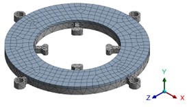
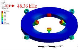
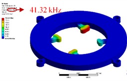
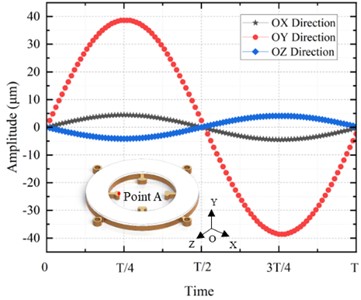
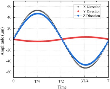
The desired vibration modes of the stator are obtained through modal analysis. Fig. 6(a) shows the mesh model of the stator. In the finite element model, the free boundary conditions are used for the ultrasonic motor. The mesh division is adaptive using the hexahedral mesh method. The finite element model has 10577 nodes and 1568 elements. Fig. 6(b) and (c) show the longitudinal bending mode and radial bending mode of the stator driving feet respectively. The corresponding resonant frequencies are 48.36 kHz and 41.32 kHz respectively. Then, the harmonic response analyses are conducted to examine the motion characteristics of the driving feet at the two mentioned resonant frequencies. To be specific, this work selects point A (see Fig. 7(a)) as the feature point and applies a 50 Vp-p sinusoidal excitation signal with frequencies of 48.36 kHz and 41.32 kHz respectively. Lastly, as shown in Fig. 7(b), the simulation results were extracted to obtain the amplitudes at point A for the two vibration frequencies. The maximum amplitude of point A along the direction is approximately 39 μm under the longitudinal bending mode of the driving foot while the maximum amplitude of point A along the direction is approximately 55 μm under the radial bending mode. The vibration amplitude of the stator ring is an order of magnitude smaller than the amplitude of the driving feet, which can be obtained in the results of modal analysis and harmonious response analysis. The operating principles for the 2-DOF motions of the linear-rotary motor were successfully verified using Finite Element Method (FEM).
Table 1Major material characteristic parameters of stator model
Materials | PZT-8 | Phosphor bronze |
Density (kg/m3) | 7650 | 8800 |
Poisson’s ratio | 0.31 | 0.3 |
Elastic modulus (×1010 N/m2) | 117 | |
Piezoelectric constant (C/m2) | – |
Fig. 6Simulation results of the stator: a) meshed model of the stator; b) out-of-plane vibration mode; c) in- plane vibration mode
a)
b)
c)
Fig. 7The amplitude of point A under different vibration modes in one cycle: a) the amplitude at point A under the out-of-plane vibration mode; b) the amplitude at point A under the in-plane vibration mode
a)
b)
Moreover, analyzing the trajectory of point P helps to enhance understanding of the motor's operation. The trajectory depicted in Fig. 5 appears as an inclined straight line, which conforms to the friction driving principle of ultrasonic motor. The finite element analysis confirms that the motor stator’s working mode can effectively drive the rotor to rotate through friction, meeting the requirements.
4. Experiment and summaries
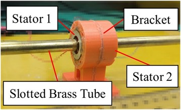
As shown in Fig. 8, the prototype of the proposed linear-rotary ultrasonic motor has been fabricated and assembled according to the structural design. Two stators (Φ 25 mm × 1.5 mm) are symmetrically attached to both sides of the 3D-printed bracket. The weight of a single stator is 3 g and the total weight of two stators is 6 g.
Fig. 8Prototype of the linear-rotary ultrasonic motor
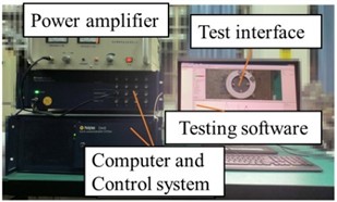
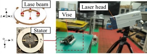
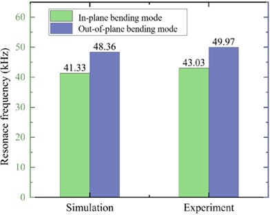
In order to measure the vibration characteristics of the stator, a laser Doppler scanning vibrometer system (PSV-W-500, Polytec GmbH, Waldbronn, Germany) is used to measure the frequency response characteristics of the stator (see Fig. 9(a)). The testing system mainly consists of a power amplifier, a laser head, a computer and a control system. Fig. 9(b) shows the test method used to measure the vibration characteristics of the driving feet. The testing results (see Fig. 10) illustrate that the resonant frequencies of the out-of-plane vibration and the in-plane vibration of the driving feet are 49.97 kHz and 43.03 kHz respectively. These values are slightly different from the simulation results, with errors of 3 % and 4 %, respectively (see Fig. 11). Differences between simulation frequencies and test results can be attributed to variations in material properties, boundary conditions between actual prototypes and finite element models as well as the omission of electrodes and glue layers in simulation models [46].
Fig. 9The test setup for the vibration characteristics: a) test system; b) laser vibration measurement position, stator position and laser head
a)
b)
Fig. 10 shows the vibration shape of the stator under the corresponding working vibration mode when the motor is in linear motion. The four driving feet exhibit simultaneous positive bending or simultaneous negative bending under the out-of-plane vibration mode, which is consistent with the simulation results. As shown in Fig. 10, the vibration shape of the driving foot is consistent with the simulation result. The left side of the driving foot is higher than the right side and the laser vibrometer is tilted at a certain angle instead of facing the surface of the driving foot. This demonstrates the in-plane vibration of the driving feet. Therefore, the stator designed in the simulation environment is preliminarily verified through vibration tests.
Fig. 10The vibration characteristics of the driving foot
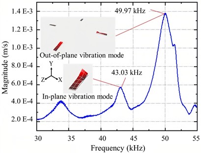
Fig. 11Comparison of the resonant frequencies under the motor’s out-of-plane bending and in-plane bending mode by simulation and experiment
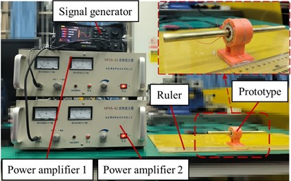
The experiment platform, as shown in Fig. 12, is then established to test the mechanical output performance of the prototype. The platform mainly consists of a signal generator, two power amplifiers, a ruler used for measuring linear velocity and a laser velocimeter used for measuring rotary velocity. In order to determine the optimal driving frequency for this prototype, the excitation voltage is set to 200 Vp-p and the input signal is a sawtooth wave.
Fig. 12Output characteristic test platform
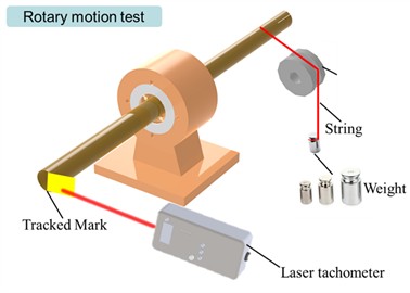
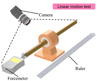
To experimentally verify the mechanical performance of the two-degree-of-freedom ultrasonic motor, a test platform was established to validate the motor’s rotational and linear motion performance. The rotary motion test platform is shown in Fig. 13(a). A thin fluorescent marker is attached to the end of the shaft, and the rotational speed is measured by aligning the laser generated by the laser tachometer (DM6230) with the fluorescent marker. Additionally, to study the motor's load-bearing capacity, a rope pulley system was established for rotational drive, and external load tests were conducted by varying the weight. The linear motion test platform is shown in Fig. 13(b). The camera is used to record the linear motion of the motor, and the linear velocity is calculated indirectly using a ruler. In addition, the output force of the motor is measured using a force gauge (FUMA, FG-2).
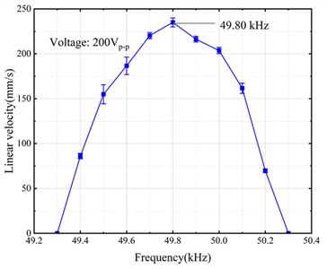
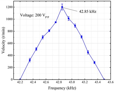
As depicted in Fig. 14(a) and Fig. 15(a), the relationships between velocity and frequency as well as the rotating velocity and frequency of the prototype motor are illustrated. The motor has a maximum linear velocity of 235 mm/s at the resonant frequency of 49.80 kHz and a maximum rotational velocity of 1200 r/min at the resonant frequency of 42.85 kHz under a voltage of 200 Vp-p. The frequency bandwidth for the linear motion of the motor is approximately 1.0 kHz while the frequency bandwidth for the rotary motion of the motor is approximately 1.3 kHz. This indicates that linear motion is more sensitive to changes in frequency.
Fig. 13Experimental setup for motor’s rotary and linear motion measurement: a) rotary motion testing platform; b) linear motion testing platform
a)
b)
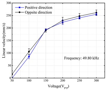
Fig. 14Output characteristics of the linear motion: a) linear motion frequency sensitivity; b) the forward and backward linear motion velocity versus the exciting voltage
a)
b)
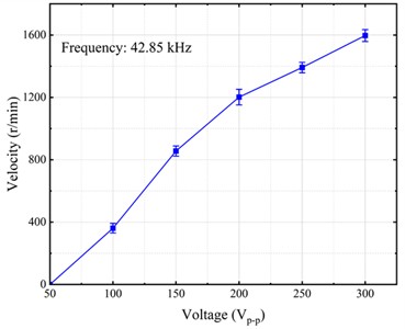
The relationship between the output performance of the prototype and the voltage is plotted in Fig. 14(b) and Fig. 15(b). With a step size of 50 Vp-p, the output characteristics of the prototype were measured in the range from 50 Vp-p to 300 Vp-p. The high driving voltage of the motor can cause severe heating of the motor stator, which can easily cause damage to the motor. Therefore, the maximum driving voltage is set to 300 Vp-p. It is obvious that the linear velocity and rotary velocity are directly proportional to the voltage, although the magnitude of the linear velocity decreases slightly with an increase in voltage. The maximum forward linear velocity is 265 mm/s while the maximum backward linear velocity is 255 mm/s. Besides, the rotational velocity is 1600 r/min under a voltage of 300 Vp-p.
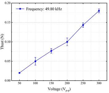
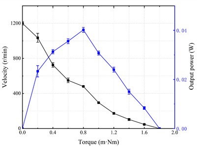
The thrust-voltage curve was tested at a frequency of 49.8 kHz and the experimental results are shown in Fig. 16(a). It can be found that the maximum thrust is 0.18 N when the voltage is 300 Vp-p. The torque-velocity characteristic of the motor is measured at a driving frequency of 42.85 kHz and a driving voltage of 200 Vp-p. The relationship between the output performances of the prototype is plotted in Fig. 16(b). From Fig. 15 (b), it can be observed that the no-load rotational velocity is 1200 r/min and the stalling torque is 1.8 mN·m. Additionally, the maximum output power is approximately 0.04 W.
Fig. 15Output characteristics of the rotary motion: a) rotary motion frequency sensitivity; b) the rotary motion velocity versus the exciting voltage.
a)
b)
Fig. 16a) Thrust-voltage characteristic of the motor; b) Torque-velocity characteristic of the motor
a)
b)
The performance of the proposed linear-rotary ultrasonic motor is compared with several previous linear-rotary ultrasonic motors, as listed in Table 2. Wang et al proposed a novel two-degree-of-freedom ultrasonic motor that adopts one longitudinal mode and two orthogonal bending modes [34]. The maximum linear velocity and rotational velocity of the motor can reach 16 mm/s and 3319 r/min respectively. The maximum driving force and torque of the motor reached 0.06 N and 0.14 m N·m. Han et al. proposed a linear-rotary motor based on a single piezoelectric tube actuator [47]. The motor can achieve a maximum linear velocity of 6.3 mm/s and a maximum rotational velocity of 11.7 r/min, respectively. Y. Zhang et al. designed a novel two-degree-of-freedom piezoelectric rotary-linear actuator system [48]. The system can achieve linear and rotational motion with resolutions of 26 nm and 0.019°, respectively. At the same time, the system can generate a maximum driving force of 2.09 N and a maximum torque of 12.20 mN·m. Moreover, Gao et al. designed a stage that can generate motions along and about the -axis using friction drive [49]. The stage has maximum velocities of 16 mm/s in the -direction and 10.5 rpm over a stroke of 360° in the -direction, respectively. Compared to the motors mentioned above, the one proposed in this work has the advantages of a simple structure and high output velocity. The maximum linear velocity and rotational velocity of the motor can reach 265 mm/s and 1600 r/min, respectively. At the same time, the motor can reach a maximum driving force of 0.18 N and a stalling torque of 1.8 mN·m.
In addition, as a friction-driven motor, wear at the contact interface of ultrasonic motors is unavoidable. If the motor runs for an extended period, the contact interface between the stator and rotor will wear, leading to a decline in output performance and a shortened service life. The additional wear caused by the inertial stick-slip mechanism further exacerbates this phenomenon. While the proposed ultrasonic motor uses phosphor bronze as the stator and rotor material, subsequent structural optimizations will expand the coverage area of wear-resistant materials on the top of the drive feet and explore new methods for coating the stator surface with high-temperature-resistant, wear-resistant films. These measures aim to comprehensively enhance the durability of the contact interface and ensure the motor's long-term stable operation.
Table 2Features of single-phase ultrasonic motors
Voltage (Vp-p) | Top linear velocity (mm/s) | Top rotary velocity (r/min) | Top driving force (N) | Top torque (mN·m) | |
Wang et al [34] | 150 | 57.6 | 3319 | 0.06 | 0.14 |
Han et al [47] | 560 | 6.3 | 11.7 | 0.45 | 0.80 |
Zhang et al [48] | 150 | 7.33 | – | 2.09 | 12.2 |
Gao et al [49] | 90 | 16 | 10.5 | – | – |
This work | 300 | 265 | 1600 | 0.18 | 1.8 |
5. Conclusions
This paper proposes a novel configuration scheme for a simple, compact, and space-saving 2-DOF linear-rotary ultrasonic motor driven by a dual-stator system, which demonstrates unique advantages in space-constrained linear-rotary tasks. Additionally, this paper introduces a single-phase electrical signal drive method for the dual-stator system, enabling linear-rotary motion to be achieved . The research work in this paper provides new methods and valuable references for innovative configuration design, performance analysis, and improvements to piezoelectric linear-rotary actuators.
The developed prototype motor has dimensions of 200 mm × 40 mm × 63 mm. The resonance frequencies of its vibration modes were obtained by testing its vibration characteristics. The resonance frequencies are found to be 43.03 kHz and 49.97 kHz. In addition, the performance of the prototype motor was also tested. It achieves a maximum linear motion velocity of 265 mm/s, a maximum rotary velocity of 1600 r/min, a maximum thrust of 0.18 N and a stalling torque of 1.8 mN·m.
Although the designed ultrasonic motor has a specific linear-rotary speed range and load capacity, there has been limited research on linear-rotary compound motion. Therefore, future work will focus on optimizing the motor’s structure and studying the characteristics of its linear-rotary compound motion. Additionally, an accurate dynamic model will be established to construct a precise control system to improve the accuracy of positioning and tracking in linear-rotary motion.
References
-
X. Dongmei, Z. Bingjie, Y. Simiao, and Z. Xuhui, “Review on single-phase driven ultrasonic motors,” Journal of Intelligent Material Systems and Structures, Vol. 34, No. 5, pp. 525–535, Sep. 2022, https://doi.org/10.1177/1045389x221121911
-
V. Jūrėnas, G. Kazokaitis, and D. Mažeika, “3DOF ultrasonic motor with two piezoelectric rings,” Sensors, Vol. 20, No. 3, p. 834, Feb. 2020, https://doi.org/10.3390/s20030834
-
R. Ryndzionek and Sienkiewicz, “A review of recent advances in the single – and multi-degree-of-freedom ultrasonic piezoelectric motors,” Ultrasonics, Vol. 116, p. 106471, Sep. 2021, https://doi.org/10.1016/j.ultras.2021.106471
-
W. Zeng, S. Pan, L. Chen, Z. Xu, Z. Xiao, and J. Zhang, “Research on ultra-low speed driving method of traveling wave ultrasonic motor for CMG,” Ultrasonics, Vol. 103, p. 106088, Apr. 2020, https://doi.org/10.1016/j.ultras.2020.106088
-
S. Naz and T.-B. Xu, “A comprehensive review of piezoelectric ultrasonic motors: classifications, characterization, fabrication, applications, and future challenges,” Micromachines, Vol. 15, No. 9, p. 1170, Sep. 2024, https://doi.org/10.3390/mi15091170
-
Y. Hu, J. Ma, Y. Zhang, J. Li, Y. Hu, and J. Wen, “Performance comparison of two motion modes of a piezoelectric inertial linear motor and its potential application in cell manipulation,” Mechanical Systems and Signal Processing, Vol. 157, p. 107743, Aug. 2021, https://doi.org/10.1016/j.ymssp.2021.107743
-
S. Izuhara and T. Mashimo, “Design and characterization of a thin linear ultrasonic motor for miniature focus systems,” Sensors and Actuators A: Physical, Vol. 329, p. 112797, Oct. 2021, https://doi.org/10.1016/j.sna.2021.112797
-
N. Masuda, S. Izuhara, and T. Mashimo, “Miniature camera module with a hollow linear ultrasonic motor-based focus feature,” Sensors and Actuators A: Physical, Vol. 354, p. 114248, May 2023, https://doi.org/10.1016/j.sna.2023.114248
-
Y. Wang, W. Chen, J. Deng, J. Li, and Y. Liu, “Toward compact motorized lens: switch and focus a filter wheel with single piezoelectric tube,” Advanced Materials Technologies, Vol. 9, No. 1, p. 23010, Nov. 2023, https://doi.org/10.1002/admt.202301066
-
L. Chen, Y. Zhang, C. Zhou, and J. Wu, “Aerodynamic mechanisms in bio‐inspired micro air vehicles: a review in the light of novel compound layouts,” IET Cyber-Systems and Robotics, Vol. 1, No. 1, pp. 2–12, Oct. 2019, https://doi.org/10.1049/iet-csr.2018.0007
-
E. T. K. Chiang, T. Urakubo, and T. Mashimo, “Lift generation by a miniature piezoelectric ultrasonic motor-driven rotary-wing for pico air vehicles,” IEEE Access, Vol. 10, pp. 13210–13218, Jan. 2022, https://doi.org/10.1109/access.2022.3146866
-
C. Jiang, Z. Zhao, D. Lu, Z. Xu, and L. Jin, “Contact analysis and performance evaluation of ring type traveling wave ultrasonic motors based on a surface contact model,” Ultrasonics, Vol. 127, p. 106851, Jan. 2023, https://doi.org/10.1016/j.ultras.2022.106851
-
R. Ryndzionek, Sienkiewicz, M. Michna, and F. Kutt, “Design and experiments of a piezoelectric motor using three rotating mode actuators,” Sensors, Vol. 19, No. 23, p. 5184, Nov. 2019, https://doi.org/10.3390/s19235184
-
X. Li et al., “A design method of traveling wave rotary ultrasonic motors driving circuit under high voltage using single-sided hertzian contact forced oscillator model,” Micromachines, Vol. 14, No. 1, p. 64, Dec. 2022, https://doi.org/10.3390/mi14010064
-
D. Lu, H. Liu, J. Xu, T. Yang, and H. Hu, “A linear ultrasonic motor based on coupling vibration mode,” Micromachines, Vol. 13, No. 11, p. 1852, Oct. 2022, https://doi.org/10.3390/mi13111852
-
Y. Zhou, J. Chang, X. Liao, and Z. Feng, “Ring-shaped traveling wave ultrasonic motor for high-output power density with suspension stator,” Ultrasonics, Vol. 102, p. 106040, Mar. 2020, https://doi.org/10.1016/j.ultras.2019.106040
-
G. Peled, R. Yasinov, and N. Karasikov, “Performance and applications of L1B2 ultrasonic motors,” Actuators, Vol. 5, No. 2, p. 15, Jun. 2016, https://doi.org/10.3390/act5020015
-
B. Delibas and B. Koc, “Single crystal piezoelectric motor operating with both inertia and ultrasonic resonance drives,” Ultrasonics, Vol. 136, p. 107140, Jan. 2024, https://doi.org/10.1016/j.ultras.2023.107140
-
J. Niu, J. Wu, M. Cao, and L. Wu, “A traveling-wave linear ultrasonic motor driven by two torsional vibrations: design, fabrication, and performance evaluation,” IEEE Access, Vol. 8, pp. 122554–122564, Jan. 2020, https://doi.org/10.1109/access.2020.3006888
-
R. Niu, H. Zhu, and C. Zhao, “A four-legged linear ultrasonic motor: design and experiments,” Review of Scientific Instruments, Vol. 91, No. 7, p. 07610, Jul. 2020, https://doi.org/10.1063/1.5114787
-
H. Yu, Q. Quan, X. Tian, and H. Li, “Optimization and analysis of a U-shaped linear piezoelectric ultrasonic motor using longitudinal transducers,” Sensors, Vol. 18, No. 3, p. 809, Mar. 2018, https://doi.org/10.3390/s18030809
-
X. Li, C. Kan, Y. Cheng, Z. Chen, and T. Ren, “Performance evaluation of a bimodal standing-wave ultrasonic motor considering nonlinear electroelasticity: Modeling and experimental validation,” Mechanical Systems and Signal Processing, Vol. 141, p. 106475, Jul. 2020, https://doi.org/10.1016/j.ymssp.2019.106475
-
L. Wang, J. Liu, Y. Liu, X. Tian, and J. Yan, “A novel single-mode linear piezoelectric ultrasonic motor based on asymmetric structure,” Ultrasonics, Vol. 89, pp. 137–142, Sep. 2018, https://doi.org/10.1016/j.ultras.2018.05.010
-
W. M. Chen and T. S. Liu, “Modeling and experimental validation of new two degree-of-freedom piezoelectric actuators,” Mechatronics, Vol. 23, No. 8, pp. 1163–1170, Dec. 2013, https://doi.org/10.1016/j.mechatronics.2013.10.002
-
S. Shi, H. Xiong, Y. Liu, W. Chen, and J. Liu, “A ring-type multi-DOF ultrasonic motor with four feet driving consistently,” Ultrasonics, Vol. 76, pp. 234–244, Apr. 2017, https://doi.org/10.1016/j.ultras.2017.01.005
-
A. Čeponis, D. Mažeika, and D. Makutėnienė, “Development of a novel 2-DOF rotary-linear piezoelectric actuator operating under hybrid bending-radial vibration mode,” Micromachines, Vol. 12, No. 6, p. 728, Jun. 2021, https://doi.org/10.3390/mi12060728
-
A. Čeponis, D. Mažeika, P. Vasiljev, and R. Bareikis, “5-DOF cone-shaped piezoelectric positioning robot for optical systems,” Sensors and Actuators A: Physical, Vol. 354, p. 114280, May 2023, https://doi.org/10.1016/j.sna.2023.114280
-
Z. Huang, S. Shi, W. Chen, L. Wang, L. Wu, and Y. Liu, “Development of a novel spherical stator multi-DOF ultrasonic motor using in-plane non-axisymmetric mode,” Mechanical Systems and Signal Processing, Vol. 140, p. 106658, Jun. 2020, https://doi.org/10.1016/j.ymssp.2020.106658
-
Z. Li, Z. Wang, P. Guo, L. Zhao, and Q. Wang, “A ball-type multi-DOF ultrasonic motor with three embedded traveling wave stators,” Sensors and Actuators A: Physical, Vol. 313, p. 112161, Oct. 2020, https://doi.org/10.1016/j.sna.2020.112161
-
H. Li, L. Wang, T. Cheng, M. He, H. Zhao, and H. Gao, “A high-thrust screw-type piezoelectric ultrasonic motor with three-wavelength exciting mode,” Applied Sciences, Vol. 6, No. 12, p. 442, Dec. 2016, https://doi.org/10.3390/app6120442
-
Y. Wang, Q. Quan, H. Yu, D. Bai, H. Li, and Z. Deng, “Rotary-percussive ultrasonic drill: an effective subsurface penetrating tool for minor planet exploration,” IEEE Access, Vol. 6, pp. 37796–37806, Jan. 2018, https://doi.org/10.1109/access.2018.2853166
-
A. Čeponis and D. Mažeika, “Rotary-linear type piezoelectric actuator based on double-elliptical stator,” Actuators, Vol. 13, No. 12, p. 478, Nov. 2024, https://doi.org/10.3390/act13120478
-
L. Han, Z. Xu, Y. Zhang, and Y. Wang, “Development of a compact impact two-degree-of-freedom linear-rotary piezoelectric motor using one piezoelectric actuator,” Review of Scientific Instruments, Vol. 94, No. 10, p. 10500, Oct. 2023, https://doi.org/10.1063/5.0152596
-
Y. Wang, J. Deng, S. Zhang, H. Li, W. Chen, and Y. Liu, “Design of a linear-rotary ultrasonic motor for optical focusing inspired by the bionic motion principles of the earthworms,” International Journal of Smart and Nano Materials, Vol. 13, No. 2, pp. 346–365, Apr. 2022, https://doi.org/10.1080/19475411.2022.2084173
-
H. Tamura, K. Shibata, M. Aoyagi, T. Takano, Y. Tomikawa, and S. Hirose, “Single phase drive ultrasonic motor using LiNbO3 rectangular vibrator,” Japanese Journal of Applied Physics, Vol. 47, No. 5S, p. 4015, May 2008, https://doi.org/10.1143/jjap.47.4015
-
Y. Ma, M. Choi, and K. Uchino, “Single-phase driven ultrasonic motor using two orthogonal bending modes of sandwiching piezo-ceramic plates,” Review of Scientific Instruments, Vol. 87, No. 11, p. 11500, Nov. 2016, https://doi.org/10.1063/1.4967857
-
Q. Pan, E. Miao, B. Wu, W. Chen, X. Lei, and L. He, “Bio-inspired piezoelectric linear motor driven by a single-phase harmonic wave with an asymmetric stator,” Review of Scientific Instruments, Vol. 88, No. 7, p. 07500, Jul. 2017, https://doi.org/10.1063/1.4985112
-
B. Zhang and C. Li, “A rabbit shaped bidirectional linear ultrasonic motor driven by single-phase signal,” Review of Scientific Instruments, Vol. 94, No. 4, p. 04500, Apr. 2023, https://doi.org/10.1063/5.0142844
-
T. Morita, R. Yoshida, Y. Okamoto, M. K. Kurosawa, and T. Higuchi, “A smooth impact rotation motor using a multi-layered torsional piezoelectric actuator,” IEEE Transactions on Ultrasonics, Ferroelectrics and Frequency Control, Vol. 46, No. 6, pp. 1439–1445, Nov. 1999, https://doi.org/10.1109/58.808867
-
T. Morita, H. Murakami, T. Yokose, and H. Hosaka, “A miniaturized resonant-type smooth impact drive mechanism actuator,” Sensors and Actuators A: Physical, Vol. 178, pp. 188–192, May 2012, https://doi.org/10.1016/j.sna.2012.02.017
-
M. Hunstig, T. Hemsel, and W. Sextro, “Stick-slip and slip-slip operation of piezoelectric inertia drives. Part I: Ideal excitation,” Sensors and Actuators A: Physical, Vol. 200, pp. 90–100, Oct. 2013, https://doi.org/10.1016/j.sna.2012.11.012
-
D. Mazeika and P. Vasiljev, “Linear inertial piezoelectric motor with bimorph disc,” Mechanical Systems and Signal Processing, Vol. 36, No. 1, pp. 110–117, Mar. 2013, https://doi.org/10.1016/j.ymssp.2011.07.015
-
L. Wang et al., “A novel piezoelectric inertial rotary motor for actuating micro underwater vehicles,” Sensors and Actuators A: Physical, Vol. 295, pp. 428–438, Aug. 2019, https://doi.org/10.1016/j.sna.2019.06.014
-
X. Zheng, L. Wang, J. Liu, and S. Chen, “A micro radial-torsional vibration ultrasonic motor driven by single-phase signal,” IEEE Access, Vol. 12, pp. 72521–72529, Jan. 2024, https://doi.org/10.1109/access.2024.3403666
-
Y. Liu, J. Yan, L. Wang, and W. Chen, “A two-DOF ultrasonic motor using a longitudinal-bending hybrid sandwich transducer,” IEEE Transactions on Industrial Electronics, Vol. 66, No. 4, pp. 3041–3050, Apr. 2019, https://doi.org/10.1109/tie.2018.2847655
-
X. Ma, J. Liu, J. Deng, Q. Liu, and Y. Liu, “A rotary traveling wave ultrasonic motor with four groups of nested PZT ceramics: design and performance evaluation,” IEEE Transactions on Ultrasonics, Ferroelectrics, and Frequency Control, Vol. 67, No. 7, pp. 1462–1469, Jul. 2020, https://doi.org/10.1109/tuffc.2020.2972307
-
L. Han, L. Yu, C. Pan, and Y. Jiang, “A compact linear-rotary impact motor based on a single piezoelectric tube stator with two independent electrodes,” Review of Scientific Instruments, Vol. 90, No. 11, p. 11500, Nov. 2019, https://doi.org/10.1063/1.5109835
-
Y. Zhang, W. J. Zhang, J. Hesselbach, and H. Kerle, “Development of a two-degree-of-freedom piezoelectric rotary-linear actuator with high driving force and unlimited linear movement,” Review of Scientific Instruments, Vol. 77, No. 3, p. 03511, Mar. 2006, https://doi.org/10.1063/1.2185500
-
W. Gao, S. Sato, and Y. Arai, “A linear-rotary stage for precision positioning,” Precision Engineering, Vol. 34, No. 2, pp. 301–306, Apr. 2010, https://doi.org/10.1016/j.precisioneng.2009.07.003
About this article
This work was supported by the Special Exploration Project for High-level Talents of Huzhou Vocational and Technical College (Grant No. 2023TS06); General Scientific Research Projects of Zhejiang Provincial Department of Education (Grant No. Y202352861); China Postdoctoral Science Foundation (Grant No. 2024M754237); Basic Public Welfare Research Program of Wenzhou (Grant No. G2023046).
The datasets generated during and/or analyzed during the current study are available from the corresponding author on reasonable request.
Le Wang: conceptualization, investigation, resources, writing-review and editing, visualization, project administration. Hang Yu: methodology, software, validation. Xin Wang: methodology, validation, formal analysis, data curation, supervision. Senjie Fei: software, validation. Si Chen: formal analysis.
The authors declare that they have no conflict of interest.
