Abstract
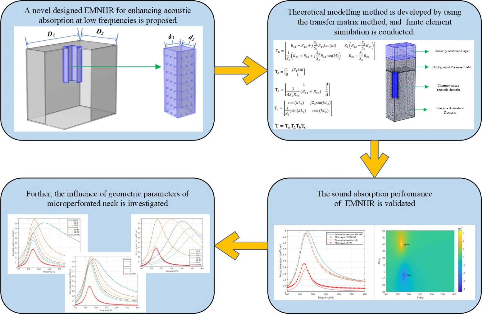
To enhance sound absorption of Helmholtz resonance metamaterials in low frequency region with simple structure and engineering practicability, according to the well-established acoustic absorption theory of micro-perforated panel, a novel designed Helmholtz resonance metamaterial with extended microperforated neck is proposed, and a theoretical modelling method is developed by using the transfer matrix method which is validated by finite element simulation. Both theoretical calculation and finite element simulation results show that sound absorption performance of proposed Helmholtz resonance metamaterial is improved significantly compared to that of Helmholtz resonator with normal neck, and the resonant absorption coefficient is close to 1. The influence of geometric parameters of microperforated neck is also investigated in detail, and some meaningful conclusions are drawn. This work provides a perfect solution for low-frequency noise control with Helmholtz resonance metamaterials.
Highlights
- A novel designed Helmholtz resonance metamaterial with extended microperforated neck is proposed.
- Sound absorption performance of EMNHR is improved significantly due to additional acoustic resistance introduced by the microperforated neck.
- According to the well-established acoustic absorption theory of MPP, the absorption coefficient can be maximized to exhibit nearly perfect absorption at the operating frequency of EMNHR.
- The proposed EMNHR can be designed and manufactured easily in engineering applications, thus providing a perfect solution for low-frequency noise control with Helmholtz resonance metamaterials.
1. Introduction
In conventional field of noise control, sound absorbing materials and structures such as porous absorbers and micro-perforated panel (MPP) resonators have been predominantly employed. However, extremely thick structures for porous materials or very deep back cavities for MPPs are required to achieve satisfactory sound absorption in low frequency region, which significantly restricts their application in space constrained environments.
Recent developments of acoustic metamaterials provide a completely new direction for low frequency noise control. Through special design, acoustic metamaterials have characteristic of high-efficiency sound absorption in the deep sub-wavelength range (their sound absorption coefficient is close to 1, while the thickness is much smaller than the operating wavelength), which shows broad application prospects in the field of low-frequency sound absorption [1]. Among various acoustic metamaterials, Helmholtz resonator (HR) is one of the most widely studied and applied sound absorbing acoustic metamaterials due to its simple structural design and independent acoustic performance determined by its own geometric parameters[2-5].
The sound absorption principle of HR lies in the sound energy dissipation via air friction and thermal dissipation across the viscous and thermal boundary layers of the pore near its resonant frequency. Scholars have done a lot of work to improve sound absorption performance of HR at low-frequencies. Most studies have focused on combining HR with dissipative porous materials to attain improved acoustic absorption at low frequencies [6-8]. Also, several successful attempts were made by structural alterations of conventional HR. The acoustic impedance and the sound absorption coefficient of HR with a tapered neck was investigated by Tang [9] to improve the sound absorption capacity. To increase the noise reduction performance at low frequencies, HR with spiral neck was proposed by Shi [10] and the resonance frequency could be efficiently lowered without increasing the total thickness. A broadband low-frequency HR absorber with rough neck was proposed by Duan [11] and Li [12], which could effectively provide the acoustic impedance required for low frequency sound absorption without changing the overall size. Duan [13] also proposed HR with petal shaped embedded neck which showed a significant improvement in peak absorption performance. Li[14] introduced a new HR design concept for drastically enhance sound absorption by bringing the cavity walls close to the pores where additional thermos-viscous dissipation along these boundaries can occur. Liu [15] proposed a honeycomb-type gradient perforated porous acoustic metamaterial paired with an embedded neck, simulation and experimental results indicate that the porous material with gradual perforation replaces the neck as the main dissipation source, which greatly increases the tunable acoustic absorption of the metamaterial.
Although great progress in sound absorption performance improvement of HR, these methods rely on complex geometrical redesign or the addition of dissipative materials, in which fine adjustment of acoustic resistance to meet critical coupling conditions is not so appropriate in engineering applications due to complexity processes or high cost. According to the well-established acoustic absorption theory of MPP [16], the acoustic properties of MPPs can be finely tuned by designing the hole size, perforation ratio, and plate thickness depending on purpose or target frequency band. Consequently, a novel designed Helmholtz resonance metamaterial with extended microperforated neck for enhancing acoustic absorption at low frequencies is proposed, and theoretical modelling method is developed by using the transfer matrix method (TMM) which is validated by finite element method (FEM), then influence of geometric parameters of microperforated neck is investigated in detail.
2. Theoretical model
Consider a typical rectangular Helmholtz resonant structure with extended microperforated neck (EMNHR) as shown in Fig. 1. The length and width of the neck are and , the depth is , the wall thickness is , the resonant cavity depth of the structure is , the length and width of the cavity are and respectively. The hole diameter and separation distance on microperforated neck are and respectively, and neck thickness is .
The interior space is divided into three volumes by interface plane between the extended neck and cavity. The volume 1 in the neck and 3 in the cavity have cross-sectional area and respectively, and the volume 2 has cross-sectional area .
Fig. 1Schematic diagram of EMNHR
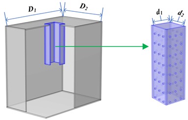
a) 3D assembly view
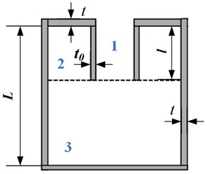
b) 2D cross-sectional view
On the side branch interface between the extended neck and cavity, the pressure and mass velocities satisfy the continuous conditions:
where and represent acoustical pressure and axial particle velocity in volume respectively, and is the time-mean density.
Similar to the analytical model of Peat [17], the linear acoustical equations of volume 1 and 2 separated by the microperforated neck can be expressed as:
where and denote mean flow velocity and fluctuating density component in volume respectively, and is given by:
where represents circumstance of the inner surface () or outer surface () of microperforated neck with according radial particle velocities .
Analytical decoupling techniques have been applied to Eqs. (3) and (4), and finally the transmission equation can be found by deriving the transmission matrix. This matrix relates the pressure and particle velocities at to those at as:
where represents the transmission matrix.
Considering the rigid boundary on bottom end of cavity, the pressure and particle velocity in volume 3 at can be written as:
where is the length of volume 3 with .
Substituting Eqs. (1), (2) and (7) into Eq. (6), and the transmission matrix for the volume 1 in the neck can be obtained:
where is the th element of transmission matrix , and is the characteristic impedance of volume 1 in the neck.
If acoustic radiation correction of the EMNHR due to cross-section changes is considered, corresponding transmission matrix can be written as:
where the end correction [4].
Furtherly, rigid boundary of the volume 2 is assumed on the top end wall which means , then the fourth row of Eq. (6) can be rewritten as:
Substituting Eq. (10) into Eq. (2), then the relationship between and can be built:
where coefficient .
Then the transmission matrix for the volume 2 in the side branch at can be obtained:
where is the characteristic impedance of the volume 2.
For the volume 3 in the cavity, the transmission matrix can be expressed as:
where and are the characteristic impedance and depth of the volume 3 respectively.
By connecting all the transmission matrices , , and , one can obtain the total transmission matrix of the EMNHR as:
Notably, to account the thermos-viscous effect, effective density and complex acoustic wave velocity[4] can be used in calculation of the transmission matrices , , and .
Finally, the relative acoustic impedance and the sound absorption coefficient of the EMNHR can be calculated as follows:
3. Results and discussion
3.1. Validation of absorption
To validate the accuracy of the aforementioned theoretical model of EMNHR, a finite element simulation using the thermos-viscous acoustic module of the COMSOL Multiphysics is conducted. The geometric parameters and microperforated parameters of EMNHR are outlined in Table 1 and Table 2 respectively. Considering symmetry of EMNHR, only 1/4 FEM model of EMNHR is built to reduce calculation load, and the detailed instructions of FEM model are shown in Fig. 2.
Table 1Geometric parameters of EMNHR
Item | Length (mm) | Width (mm) | Depth (mm) | Thickness (mm) |
Neck | 12 | 12 | 40 | 1 |
Cavity | 50 | 80 | 80 | 1 |
Table 2Geometric parameters of the microperforated neck
Hole diameter (mm) | Separation distance (mm) | Thickness (mm) |
0.3 | 5 | 1 |
Fig. 21/4 FEM model of EMNHR
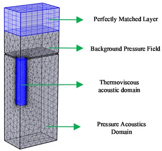
Fig. 3Sound absorption coefficient results
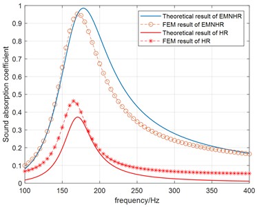
The sound absorption coefficient curves are calculated by theoretical model and FEM simulation. For comparison, both results of EMNHR and HR with normal neck are illustrated in Fig. 3. As can be seen, theoretical model results are consistent with the FEM simulation results in general. Small deviation is observed at the resonant frequencies, which may be caused by not exact estimation of end correction in this case. Therefore, the accuracy of developed theoretical model by using TMM can be validated. In addition, both the theoretical model and FEM simulation results show that sound absorption performance of EMNHR is improved significantly compared to that of HR with normal neck, and the resonant absorption coefficient is close to 1. Meanwhile, resonant frequency is shifted a little higher for EMNHR.
Fig. 4Complex plane zero-pole distributions
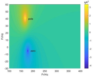
a) EMNHR
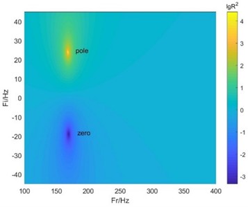
b) HR with normal neck
The complex plane zero-pole distributions of the EMNHR and HR with normal neck are displayed in Fig. 4. By introducing an imaginary part in the frequency, the reflection coefficient of the system can be drawn in the complex frequency plane to reveal physical properties of the system. When the zero point of the system falls on the real frequency axis, then the condition of critical coupling is satisfied and perfect absorption is realized. As can be found in Fig. 4, zero point of EMNHR falls very near the real frequency axis in the complex plane, whereas the zero and pole of HR with normal neck are almost symmetrically distributed about the real frequency axis. The zero-pole distributions in the complex plane evidently indicate that EMNHR can achieve nearly perfect absorption at resonant frequency, which is coincided with the results in Fig. 3.
To explore the mechanism of sound absorption enhancement by EMNHR, energy dissipation density in the neck domain for EMNHR and HR with normal neck at their resonant frequencies is demonstrated Fig. 5. By compared the results, significantly higher energy dissipation density can be observed in the neck domain of EMNHR than that of HR with normal neck, which means better sound absorption performance of EMNHR. This is due to the fact the microperforated neck with properly tuned geometric parameters can efficiently provide additional acoustic resistance to satisfy the critical coupling condition.
Fig. 5Energy dissipation density (logarithmic scale) in the neck domain
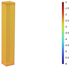
a) EMNHR
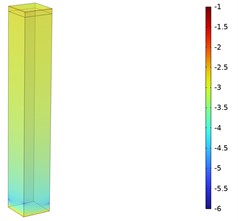
b) HR with normal neck
3.2. Influence of geometric parameters of microperforated neck
After validation and analysis of the absorption characteristic of EMNHR, the influence of geometric parameters of microperforated neck to the absorption coefficient is explored.
Firstly, let the hole diameter vary from 0.1 mm to 1.1 mm in step sizes, while the separation distance and thickness are kept constant with 4 mm and 1 mm. The relation between absorption coefficient curve and hole diameter is revealed in Fig. 6(a), also the peak absorption coefficient value versus hole diameter is given in Fig. 6(b). As can be seen, the peak absorption coefficient is increasing to nearly 1, then decreasing with increasing hole diameter. Compared to the resonance frequency of HR with normal rigid neck, a shift of the absorption maximum to a higher frequency can be observed. To interpret above results, the real part and imaginary part of the relative acoustic impedance are illustrated in Fig. 6(c). It can be found that the real part of the relative acoustic impedance is increasing at first, then decreasing with increasing , the resistance approaches nearly to 1 at 0.5 mm which corresponding to nearly perfect absorption condition. However, the imaginary part of the relative acoustic impedance is decreasing with increasing , which results a growing resonance frequency.
Then, the separation distance is set from 2 mm to 12 mm in step sizes, while the hole diameter and thickness remain unchanged with 0.3 mm and 1 mm. The relation between absorption coefficient curve and separation distance is shown in Fig. 7(a), while the peak absorption coefficient value versus hole diameter is plotted in Fig. 7(b). As illustrated in the figures, the peak absorption coefficient is also increasing to nearly 1, then decreasing with increasing separation distance. The absorption maximum shifts to a lower frequency and gets closer to resonance frequency of HR with normal rigid neck. Furtherly, the real part and imaginary part of the relative acoustic impedance are given in Fig. 7(c). It can be observed that the real part of the relative acoustic impedance is decreasing with increasing , the resistance approaches nearly to 1 at 4 mm which corresponds to the perfect absorption condition. On the contrary, the imaginary part of the relative acoustic impedance is increasing with increasing , which gives a reducing resonance frequency.
Fig. 6The influence of hole diameter
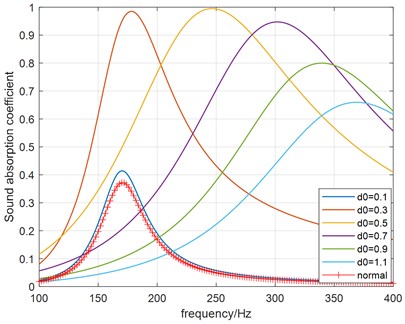
a) Sound absorption coefficient curves
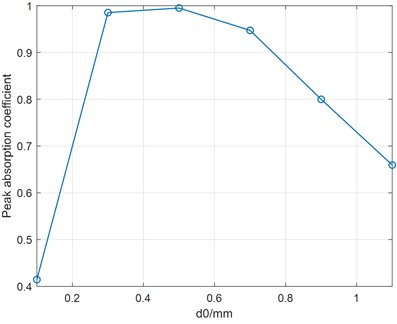
b) Peak absorption coefficient versus
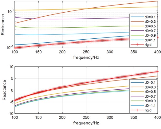
c) Real and imaginary part of
Fig. 7The influence of separation distance
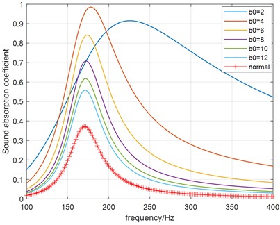
a) Sound absorption coefficient curves
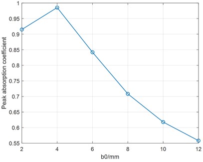
b) Peak absorption coefficient versus
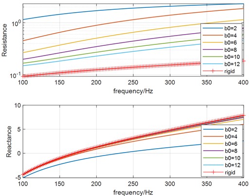
c) Real and imaginary part of
Fig. 8The influence of thickness
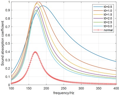
a) Sound absorption coefficient curves
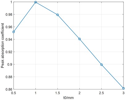
b) Peak absorption coefficient versus
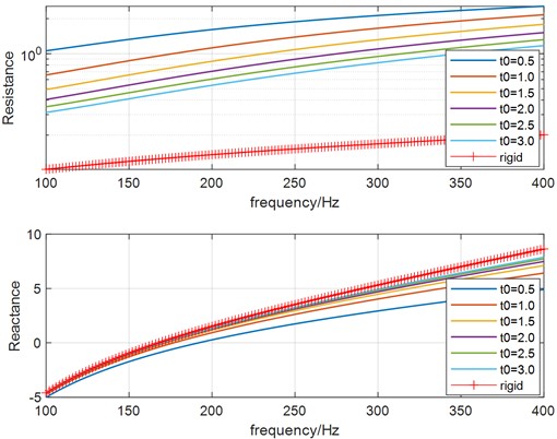
c) Real and imaginary part of
Lastly, the thickness is changed from 0.5 mm to 3.0 mm in step sizes, while the hole diameter and separation distance are held with 0.3 mm and 4 mm. The relation between absorption coefficient and thickness is illustrated in Fig. 8(a), again the peak absorption coefficient value versus hole diameter is shown in Fig. 8(b). As can be found by the figures, the influence of thickness to the absorption coefficient is similar to that of separation distance in some extent, the decreasing resonance frequency shifts toward that of HR with normal rigid neck with increasing thickness. As above, the real part and imaginary part of the relative acoustic impedance are shown in Fig. 8(c). It can be observed that the influence of thickness to the relative acoustic impedance is also similar to that of separation distance.
4. Conclusions
In order to enhance sound absorption of Helmholtz resonance metamaterials in low frequency region with simple structure and engineering practicability, according to the well-established acoustic absorption theory of microperforated panel, a novel designed Helmholtz resonance metamaterial with extended microperforated neck is proposed, and a theoretical modelling method is developed by using TMM which is validated by finite element simulation. Some meaningful conclusions can be drawn as follow:
1) Both theoretical calculation and finite element simulation results show that sound absorption performance of proposed Helmholtz resonance metamaterial can be improved significantly compared to that of HR with normal neck, and the resonant absorption coefficient is close to 1. Meanwhile, resonant frequency is shifted a little higher for EMNHR.
2) Significantly higher energy dissipation density can be observed in the neck domain of EMNHR than that of HR with normal neck, which means better sound absorption performance. The mechanism of sound absorption enhancement by EMNHR lies in the fact the microperforated neck with properly tuned geometric parameters can efficiently provide additional acoustic resistance to satisfy the critical coupling condition.
3) The influence of geometric parameters of microperforated neck is also investigated in detail. According to the well-established acoustic absorption theory of micro-perforated panel, the microperforated neck can be designed by an optimization method in which the absorption coefficient is maximized to exhibit nearly perfect absorption at the operating frequency of EMNHR.
4) Compared to other methods, the advantages of proposed EMNHR lie in simple geometrical structure as normal HR and complete freedom from addition of other dissipative materials. Based on the fine-tuned ability of acoustic absorption properties and multiple batch manufacturing approaches (including mechanical stamping, laser drilling, electrochemical etching, MEMS-based processing, and additive manufacturing techniques, et al.) of MPP, the proposed EMNHR can be designed and manufactured easily in engineering applications, thus providing a perfect solution for low-frequency noise control with Helmholtz resonance metamaterials.
References
-
S. Kumar and H. P. Lee, “Recent advances in acoustic metamaterials for simultaneous sound attenuation and air ventilation performances,” Crystals, Vol. 10, No. 8, p. 686, Aug. 2020, https://doi.org/10.3390/cryst10080686
-
N. Jiménez, V. Romero-García, V. Pagneux, and J.-P. Groby, “Rainbow-trapping absorbers: Broadband, perfect and asymmetric sound absorption by subwavelength panels for transmission problems,” Scientific Reports, Vol. 7, No. 1, Oct. 2017, https://doi.org/10.1038/s41598-017-13706-4
-
J. Guo, Y. Fang, Z. Jiang, and X. Zhang, “Acoustic characterizations of Helmholtz resonators with extended necks and their checkerboard combination for sound absorption,” Journal of Physics D: Applied Physics, Vol. 53, No. 50, p. 505504, Dec. 2020, https://doi.org/10.1088/1361-6463/abb5d8
-
S. Yan, F. Wu, X. Zhang, D. Zhang, and Z. Wu, “Rectangular extended neck Helmholtz resonant acoustic structure for low frequency broadband sound absorption,” Physica Scripta, Vol. 99, No. 7, p. 075004, Jul. 2024, https://doi.org/10.1088/1402-4896/ad4deb
-
X. H. Du, R. F. Mao, and H. C. Zhu, “Influence of element distance on acoustic propagation characteristics of helmholtz resonator arrays,” (in Chinese), Noise and Vibration Control, Vol. 44, No. 5, pp. 88–92, May 2024.
-
T. Lee, T. Nomura, and H. Iizuka, “Damped resonance for broadband acoustic absorption in one-port and two-port systems,” Scientific Reports, Vol. 9, No. 1, Sep. 2019, https://doi.org/10.1038/s41598-019-49222-w
-
B. Cheng, N. Gao, Y. Huang, and H. Hou, “Broadening perfect sound absorption by composite absorber filled with porous material at low frequency,” Journal of Vibration and Control, Vol. 28, No. 3-4, pp. 410–424, Dec. 2020, https://doi.org/10.1177/1077546320980214
-
X. Li, B. Liu, and Q. Wu, “Enhanced Low-Frequency Sound Absorption of a Porous Layer Mosaicked with Perforated Resonator,” Polymers, Vol. 14, No. 2, p. 223, Jan. 2022, https://doi.org/10.3390/polym14020223
-
S. K. Tang, “On Helmholtz resonators with tapered necks,” Journal of Sound and Vibration, Vol. 279, No. 3-5, pp. 1085–1096, Jan. 2005, https://doi.org/10.1016/j.jsv.2003.11.032
-
X. Shi and C. Ming Mak, “Helmholtz resonator with a spiral neck,” Applied Acoustics, Vol. 99, pp. 68–71, Dec. 2015, https://doi.org/10.1016/j.apacoust.2015.05.012
-
M. Duan, C. Yu, Z. Xu, F. Xin, and T. J. Lu, “Acoustic impedance regulation of Helmholtz resonators for perfect sound absorption via roughened embedded necks,” Applied Physics Letters, Vol. 117, No. 15, Oct. 2020, https://doi.org/10.1063/5.0024804
-
T. Li, F.-M. Wu, T.-T. Zhang, J.-J. Wang, B. Yang, and D. Zhang, “A low-frequency wideband ventilation muffler based on an embedded rough-necked Helmholtz resonator,” (in Chinese), Acta Physica Sinica, Vol. 72, No. 22, p. 224301, Jan. 2023, https://doi.org/10.7498/aps.72.20231047
-
M. Duan, C. Yu, W. He, F. Xin, and T. J. Lu, “Perfect sound absorption of Helmholtz resonators with embedded channels in petal shape,” Journal of Applied Physics, Vol. 130, No. 13, Oct. 2021, https://doi.org/10.1063/5.0064811
-
X. Li, X. Yu, J. W. Chua, and W. Zhai, “Harnessing cavity dissipation for enhanced sound absorption in Helmholtz resonance metamaterials,” Materials Horizons, Vol. 10, No. 8, pp. 2892–2903, Jul. 2023, https://doi.org/10.1039/d3mh00428g
-
X. Liu et al., “Low-frequency broadband acoustic absorption characteristics of honeycomb-type gradient perforated porous acoustic metamaterials paired with embedded necks,” Applied Acoustics, Vol. 233, p. 110626, Mar. 2025, https://doi.org/10.1016/j.apacoust.2025.110626
-
D.-Y. Maa, “Potential of microperforated panel absorber,” The Journal of the Acoustical Society of America, Vol. 104, No. 5, pp. 2861–2866, Nov. 1998, https://doi.org/10.1121/1.423870
-
K. S. Peat, “A numerical decoupling analysis of perforated pipe silencer elements,” Journal of Sound and Vibration, Vol. 123, No. 2, pp. 199–212, Jun. 1988, https://doi.org/10.1016/s0022-460x(88)80106-8
About this article
We would like to acknowledge financial supported by Hunan Provincial Natural Science Foundation of China (Grant No. 2023JJ50517).
The datasets generated during and/or analyzed during the current study are available from the corresponding author on reasonable request.
Xianghua Du: methodology and validation. Rongfu Mao: conceptualization and supervision.
The authors declare that they have no conflict of interest.
