Abstract
A two-wheeled self-balancing mobile robot (TWBMR) represents a complex motion control system characterized by multi-variable, nonlinear, high-order, strong-coupling dynamics, and intrinsic instability. Aiming at the complexity of system development, this paper proposes an embedded software development approach based on model-based design (MBD) using Matlab/Simulink. By integrating a control strategy that combines a digital motion processing (DMP) attitude solver with a PID control algorithm, and leveraging the Android platform along with a Bluetooth communication module for online parameter tuning, effective self-balancing control of the TWBMR is achieved. Experimental results demonstrate that the system exhibits high accuracy in Bluetooth-based data transmission and reception, excellent control precision, robust system stability, and rapid time response. The main contribution of this paper is to make focus on concretely building a unique model architecture of the TWBMR control system able to implement all the major aspects of MBD methodology such as executable requirements and Processor-In-the Loop (PIL) simulation modes, verification and automatic code generation. It is a great advantage to develop the system faster and more efficiently, shorten the prototyping process.
1. Introduction
With the rapid development of sensor technology, communication technology, automatic control technology and artificial intelligence technology, robots are more and more widely used in industrial, agricultural, medical and military fields. A TWBMR is an inverted pendulum-like system that maintains balance through the torque output of motors to the left and right wheels [1], featuring compact structure, high efficiency of control and flexibility of turning, etc. It is more and more widely used in the fields of traffic, security, inspection, food service, etc., and it has become a hot spot of research in the field of mobile robots.
Meanwhile, the TWBMR is a multivariable, nonlinear, high-order, strongly coupled and intrinsically unstable motion control system [2-5], which is a typical device to test various control theories and control methods. Thus, its study has great theoretical and practical significance.
As early as the 1950s, experts in control theory at the Massachusetts Institute of Technology (MIT) designed an inverted pendulum system to study the attitude control problems in the guidance process of rockets and missiles [6], and used it to verify the various attitude control strategies proposed.
In 1986, Prof. Yamato and his team in Japan, Matsushita Electric Industrial Co., Ltd. (now Panasonic Corporation) developed the first successful self-balancing robot, the robot is also known as the ‘dynamic balance car’ [7], which set off the prelude to the study of two-wheeled self-balancing robots.
In 1995, American Dean Kamen announced the development of a full-fledged self-balancing robot. Kamen announced the mature self-balancing vehicle products Segway [8], the internal use of solid-state gyroscopes to measure the angular velocity of the balance of the car, the use of high-speed operation of the central processor on the balance of the real-time tilt angle of the car for the solution, is the world’s first truly commercial self-balancing vehicle.
In 2002, the Industrial Electronics Laboratory of the Swiss Federal Institute of Technology (ETH) designed an autonomous mobile self-balancing robot JOE [9], using linear state space theory to design the control algorithm, the controller obtains the tilting angular velocity through the gyroscope, and integrates the angular velocity to get the tilting angle, and obtains the forward speed of the vehicle through the encoder, so that it adjusts the robot's attitude and achieves the balancing purpose.
In 2008, Tiger Electronics Company of the United States and Sega Toys Company of Japan launched a two-wheeled robotic toy AMP (Automated Musical Personality) [10] by applying advanced gyroscope technology with infrared sensors and sonar technology.
In 2015, China Xiaomi Ninebot launched the classic ‘Nine Balance Bike’ (Ninebot) [11], which is different from the traditional walking tools, it supports Bluetooth connection to mobile phone APP, real-time monitoring and controlling the status of the vehicle, which is very popular and popular in the market.
Currently, the development and research of the TWBMR control systems predominantly follow the traditional development process. During the design phase, a hardware platform must be constructed, which necessitates substantial initial investment. Testing can only commence after the prototype is completed, leading to high costs for error detection and correction, thereby posing significant market risks. Software programming relies on traditional manual methods, which demand high personnel expertise, are labor-intensive, inefficient, and prone to errors. To enhance the development efficiency of the TWBMR and reduce costs.
This paper proposes a MBD methodology, integrating the mainstream V-model development process. Through the establishment of a hardware experimental platform, the various functionalities of the TWBMR are validated, thus verifying the feasibility of the model-based design approach. The parallel PID control strategy based on upright, velocity and direction loops are particularly suitable for scenarios with high dynamic performance requirements, which satisfy the stability, rapidity and accuracy of the control system. Integration with the Android platform provides a user-friendly interface and remote control, making the TWBMR more accessible for practical applications.
2. Construction of the TWBMR control system
The TWBMR can be simplified as a first-order inverted pendulum mode with a movable bottom, as shown in Fig. 1. The height of the center of gravity of the body is , the mass is , and the inclination angle is . Force analysis of the model gives the equation of motion between the acceleration of the wheels of the balanced robot, and the acceleration of the external disturbance:
Fig. 1The TWBMR simplified model
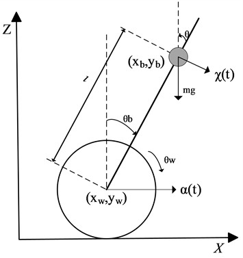
When the inclination is small, the equation of motion Eq. (1) is simplified to:
When in equilibrium, that is, , then:
According to the analysis of the above formula, the angle and the current angular acceleration of the robot are accurately detected, which are taken as feedback values and controlled by the algorithm to realize the balance control of the wheeled robot.
2.1. Overall framework design of the TWBMR
The operation principle of the TWBMR is to establish a kind of ‘dynamic stability’, the self-balancing ability is based on real-time detection of the robot body state and feedback sensing data to the central controller, and then the central controller according to the algorithm given to the robot body state of the movement instructions by the motor drive module to drive the motor to keep the robot body upright. The upright movement of the TWBMR can be separated into three basic parts for control.
1) Balance control: Maintaining the upright balance state by controlling the forward and reverse rotation of the robot motor.
2) Speed control: By adjusting the tilt angle to achieve speed control, it is essentially achieved by controlling the motor speed to control the wheel speed.
3) Direction control: Steering control is achieved by controlling the rotational differential between two motors.
The design takes STM32 microcontroller as the main control chip, which collects and processes data from the gyroscope sensor, encoder, ultrasonic sensor, and instructions sent by the intelligent terminal in real time. After processing the data, STM32 transmits the terminal through the Bluetooth module. The system is remotely controlled and data is processed using an APP based on the Android system to enhance the autonomy, security, and reliability of the system. The overall design block diagram of the system is shown in Fig. 2.
Fig. 2Block diagram of the TWBMR
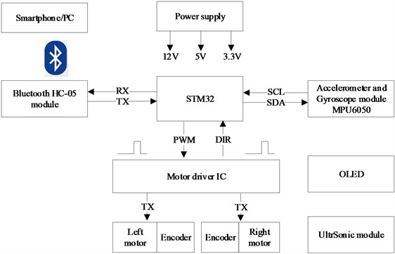
The TWBMR is composed of three parts: the main control, the peripheral devices and the power supply. The main control part takes the STM32 microcontroller as the core controller. The peripheral devices include the BLE module, ultrasonic distance measurement module, attitude measurement sensor MPU-6050, OLED display, LED, buzzer, encoder, TB6612FNG motor driver and two encoded motors. The power supply provides power for the TWBMR and outputs three voltages of 12 V, 5 V and 3.3 V. Socket protocol is used for data communication between the TWBMR and the smart terminal APP.
2.2. Establishment of balance algorithm
The power of the TWBMR lies in its two wheels, which are responsible for maintaining the robot's balance, speed, and direction. The speed control of the robot is achieved by adjusting its elevation or tilt angle, ultimately relying on the synchronization of the rotational speeds of the two motors.
The design of the balancing algorithm is the core technology for implementing the TWBMR. Currently, various control theories have been proposed, among which the control algorithms commonly used in practical applications include conventional PID control [12-13], Linear Quadratic Regulator (LQR) [14], fuzzy control [15-17], sliding mode variable structure control [18], and neural network control algorithms [19].
Cihan et al. conducted research on the TWBMR utilizing the LQR [20]. They employed a high-performance, large-torque direct current servo motor, a transistor pulse width modulation (PWM) direct current servo control module, and a high-precision sensor to achieve upright control of the TWBMR.
Ching‐Chih Tsai et al. established the dynamic model of the TWBMR [21]. S.A. Trefilov et al. adopted the robust pole placement method to perform stability control on the TWBMR [22]. Sangtae Kim et al. designed a PID controller and achieved the control of the coaxial TWBMR [23]. Emrah ATAC et al. proposed the application of PID control method to reduce the training time during the Reinforcement Learning (RL)-based training of self-balancing robots [24].
The Anh Mai et al. proposes a hierarchical fuzzy control method [25]. Two fuzzy controllers are used to control the offset angle of the robot body and the rotation speed of the wheels respectively. The decision-maker coordinates the proportions of the two control quantities of standing upright and walking. Finally, the correctness of the design is verified through simulation.
Lucas Lins Souza et al. proposed a nonlinear control strategy for an inverted pendulum-type TWBMR in the presence of uncertainties, establishing a comprehensive nonlinear model that accounts for external disturbances [26]. Leveraging Active Disturbance Rejection Control (ADRC), the proposed algorithm is characterized by its lightweight nature, enabling implementation on embedded systems with limited processing capabilities.
Omar Mohamed Gad et al. designed and implemented the control system for the TWBMR by utilizing MATLAB and the Arduino IDE [27]. Firstly, the transfer function of the TWBMR was derived through mathematical modeling based on the Lagrange equation. Subsequently, a cascade PID controller was employed to ensure the robot's balance.
The core of PID control algorithm is closed-loop control, and because of the uniqueness of the TWBMR, the control is divided into angle loop control, direction loop control and speed loop control.
Since the upright control of the TWBMR requires the angular velocity and angular acceleration measured by the gyroscope and accelerometer as input parameters, and the data measured by the gyroscope and accelerometer during dynamic movement are subject to interference errors, if integral control is added, it will lead to error accumulation and the failure of PID control. Therefore, only PD control is needed to achieve the upright function of the TWBMR.
Since the running speed of the TWBMR is related to its tilt angle, for instance, to increase the speed of the robot moving forward, the angle of the robot tilting forward needs to be increased. After the tilt angle increases, the wheels need to move forward under the upright control to maintain the balance of the robot, and the speed increases. Considering that the encoder motor may have noise, to prevent the noise from being amplified, PI control is chosen for speed control.
The steering control of the TWBMR is based on the speed loop, combined with the angle of the gyroscope in the -axis direction, and the steering function is achieved by controlling the speed difference of the left and right motors. Considering that the TWBMR itself has heavy objects such as batteries installed, which may cause the TWBMR to overshoot during steering, a PI algorithm is adopted to suppress the overshoot.
From the perspective of control, the input of the TWBMR is the speed of the two motors. Therefore, by controlling the rotational speed of the two motors, the balance, speed and direction of the car can be controlled. At the same time, to integrate and debug the PID parameters, the speed is set to a fixed value. The speed control system will consist of negative feedback upright PD controller and a positive feedback speed PI controller. The control algorithm is shown in Eq. (4):
where is the angle, is the angular velocity, and are respectively the proportional coefficient and differential coefficient in the upright PD control, and are respectively the proportional coefficient and integral coefficient in the speed PI control, is the deviation between the expected speed and the feedback speed, and is the integral of the speed control deviation.
The vertical ring and the speed ring can only realize the car running in a straight line, and the steering ring needs to be added to realize the robot steering. The two uses of the steering ring are as follows:
(1) Inhibitory steering: Due to the errors of the two motors and wheels of the robot, even if the same PWM is given to both wheels, different speeds may be output, causing the car to rotate slightly in place. At this time, a steering loop is needed to suppress the rotation of the car and make it move in a straight line. The parameters can be selected with negative polarity to suppress the rotation. The -axis angular velocity is collected. If it is a left turn, the steering loop parameter is taken as positive and added to the left wheel, and then subtracted from the right wheel. By increasing the speed of the left wheel and reducing the speed of the right wheel, it will turn right. The differential link is adopted:
(2) Expectation turning: When using a Bluetooth remote control to steer a vehicle, the vehicle must possess a steering function. Therefore, the suppression effect should be removed, and the desired steering angle should be used as input, with adjustments made through a proportional control system:
So far, we get a control algorithm that keeps the robot upright with a given speed, consisting of negative feedback upright PD controller, a positive feedback velocity PI controller and a positive feedback direction PD controller. The control principle of the TWBMR is shown in Fig. 3.
Fig. 3The TWBMR PID control system
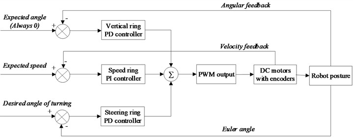
First, the angular velocity and angular acceleration measured by the gyroscope and accelerometer are filtered through the MPU6050 DMP, and then used as the PD control entry parameters for PD control.
The speed control is based on the vertical control, the pulse number measured by the left and right encoder is taken as the input parameter of PI control, and the PWM duty ratio is output by the PI controller to control the motor speed, so as to ensure the balance of the TWBMR in the moving state.
The steering control takes the speed difference of the left and right motors as the inlet parameter of the steering ring PD control, outputs the balance value and converts it into PWM duty ratio, and controls the left and right motor drives to achieve balance control.
By constructing upright ring, speed ring and direction ring, PWM output of motor speed regulation can be obtained. The control structure based on parallel PID designed above is suitable for scenes requiring high dynamic performance, which is different from the previous cascade PID and is suitable for scenes requiring long-term stable operation (such as fixed-point balance and low-speed Cruise).
3. Bluetooth control
With the development of science and technology into the IoE era, the TWBMR as intelligent hardware must has interconnection and intelligence. Bluetooth technology is a wireless communication technology that works in the 2.4 GHz ISM band. It adopts fast confirmation and frequency hopping mode, which makes Bluetooth communication have good anti-interference ability and system stability.
On the one hand, Bluetooth communication in the TWBMR is utilized to monitor the real-time operational data of the PC for debugging and performance optimization. On the other hand, it enables real-time interactive communication with the intelligent terminal application, facilitating information transmission and response between the robot and the terminal, thereby enhancing the overall intelligence of the control system.
Fig. 4Bluetooth control module workflow
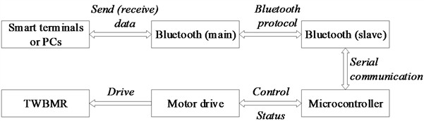
The workflow of Bluetooth control module is shown in Fig. 4. The Bluetooth module is used for communication between the APP and the TWBMR, and can achieve functions such as controlling the TWBMR movement and steering, viewing data, PID tuning, etc.
(1) The Bluetooth control module uses the Bluetooth-enabled components of the Android-based platform to interactively communicate with the Bluetooth master module.
(2) The Bluetooth protocol is employed, with the driver circuit acquiring balance correction control data and transmitting it to the Bluetooth slave module under the control of the microcontroller self-balancing module.
(3) The Bluetooth slave module on the smart terminal utilizes serial communication to establish a communication link with the microcontroller.
4. The TWBMR modeling based on STM32-MAT
The MBD embedded software development method, utilizing the MATLAB/Simulink platform, involves creating a control system model within the MATLAB/Simulink environment and conducting offline simulations. Subsequently, the interface is modified to a Simulink driver module that is compatible with a specific hardware platform. Using the code generation tool, the control system model is transformed into an executable program for the hardware board, which is then automatically downloaded to the hardware platform for testing and verification of the control system. The rapid prototype controller, developed based on the V-model, significantly accelerates the development and verification of control algorithms, resulting in transformative changes within the control industry. The Real-Time Workshop (RTW) toolbox provided by MATLAB offers automatic code generation capabilities, allowing for the direct conversion of Simulink models into custom C code for target boards. The integration of Simulink and RTW tools empower developers to rapidly establish and verify control solutions within a visual development platform, marking a significant advancement in the development of rapid prototype controllers.
The STM32 series microcontrollers are embedded application products based on the ARM Cortex-M3 core. Their high performance, low cost, and low power consumption contribute to the continual expansion of their application fields, underscoring the importance of efficient development and utilization. The STM32 MCU's code generation capabilities are fully supported by MathWorks, allowing software developers to create algorithms within the MATLAB and Simulink environments. These algorithms can then be compiled for PIL simulations, facilitating the integration, debugging, and testing of the models. The C code generated by Embedded Coder is designed to run on the STM32 microcontroller, thereby simplifying the code integration process.
The MBD of the TWMR facilitates the integrated development of embedded systems using software tools such as Simulink and STM32 Cube MX. Initially, the STM32 microcontroller is selected as the system controller, and STM32 Cube MX is employed to configure its clock settings and pin assignments. Subsequently, Simulink serves as the platform for designing the parallel PID algorithm. Finally, the model developed in Simulink is converted into a C file, and a HEX file is generated using MDK Keil software, which is then downloaded to the STM32 microcontroller.
4.1. TWBMR control flow
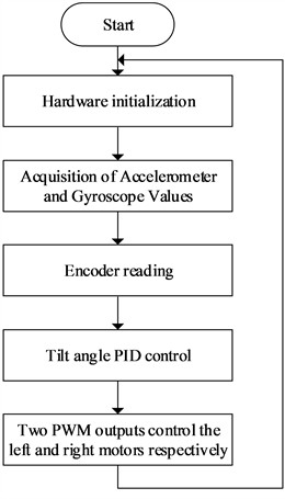
The TWBMR serves as a typical inverted pendulum model. According to the self-balancing principle of the robot, when the sensor detects that the angle deviates from the preset mechanical zero angle indicating that the vehicle body is tilting motor intervention is necessary. To maintain balance, the motor must drive the robot forward or backward to generate acceleration, thereby allowing the center of gravity to shift and achieve dynamic equilibrium within the system. The control flowchart of the system is shown in Fig. 5.
Step 1. Attitude solving of the TWBMR is performed by accelerometer value and gyroscope value acquisition.
Step 2. Read the encoded value of the encoded motor rotation during the timer interrupt time.
Step 3. Feed the attitude angle and encoding value into the PID controller to calculate PWM.
Step 4. Control the motor to rotate forward and backward according to the PWM value. If the PWM is negative, the motor will rotate in reverse; otherwise, it will rotate forward. And output the absolute value of PWM to the motor drive to control the motor speed.
Fig. 5Flow chart of the TWBMR control
4.2. The TWBMR control system model
The environment software tools to be installed and configured for the TWBMR model-based development are shown in Table 1.
Matlab/Simulink: a powerful and flexible simulation platform based on Simulink, enabling system modeling and simulation in many fields. It provides a rich module library, graphical modeling interface, and professional toolbox, supporting the full process application from algorithm design to hardware deployment.
STM32CubeMX: a graphical configuration tool designed specifically for STM32 microcontrollers. With its intuitive and easy-to-use graphical interface, users can easily configure and initialize various parameters of the STM32 chip, including pin allocation, clock configuration, and peripheral initialization, ultimately generating underlying driver code automatically.
Table 1STM32 code auto-generation related software tools
Software | Introduction |
Matlab/Simulink | Integrated environment for dynamic system modeling, simulation, and comprehensive analysis |
Embedded Coder | Embedded system code generation |
Keil MDK-ARM | Microcontroller/embedded C language software development environment |
STM32CubeMX | Generate the driver code of STM32 microcontroller according to the required functions |
STM32-MAT/Target | Matlab/Simulink library for stm32 |
Keil MDK-ARM: an IDE widely used in embedded system development, providing powerful tools such as compilers, debuggers, simulators, etc., enabling developers to efficiently write, compile, debug, and burn embedded program code.
STM 32-MAT/Target toolkit: the MCU CONFIG module provided can be configured for any STM32 processor chip supported by STM32CubeMX and encompasses nearly all resources available on STM32 chips. During embedded software development, complex control algorithms and embedded programming can be implemented by integrating existing Matlab/Simulink modules. Leveraging the configuration capabilities of STM32CubeMX software, graphical design, early verification, automatic code generation, and automated documentation can be efficiently achieved for STM32 microcontrollers.
The whole design process is systematically divided into three key stages: first, the algorithm of the control system is designed on Matlab/Simulink, and then the PIL simulation, that is, the real-time simulation of STM32 microcontroller and Matlab/Simulink connected through UART. This process requires the collaboration of Matlab/Simulink, stm32cubemx, toolchain and other software, so that the model of automatically generated code can be built, and the corresponding input and output of the design model can be connected with the modules of STM 32-MAT/Target library. According to the specific settings in STM32CubeMX according to the model functions, the code can be automatically generated, and the generated C code engineering file can be generated through the corresponding development environment. The model-based design process of microcontroller is completed by recompiling and programming.
4.2.1. The formulation and allocation of tasks
Stateflow is an important tool in MATLAB/Simulink, based on finite state machines and flowcharts, specifically designed for designing and simulating state machine and event driven systems. Users can easily define multiple states and transitions between states by dragging and dropping components and setting state relationships, achieving the system's state logic. Open the Stateflow option to design the TWBMR task scheduling flowchart as shown in Fig. 6.
In accordance with the TWBMR control requirements, the STM32 SysTick timer is utilized to manage the motor’s timing interrupt at a frequency of 1 millisecond. Specifically, the inner speed loop is regulated by capturing the encoded pulse, and the current and direction of the left and right motors are adjusted accordingly. To achieve this, time slice scheduling tasks are established at intervals of 5 milliseconds, 10 milliseconds, and 20 milliseconds, respectively, to control the TWBMR balance loop, speed loop, and direction loop.
4.2.2. Balanced-loop PD control and output
Extract and install the en.stm32-mat_target.zip hardware support package, with the default installation path being “C:\MATLAB\STM32-MAT\STM32”. Add this path to MATLAB working path, and when running Simulink, open the simulation/library browser option to see all available modules in Simulink (including the newly installed STM32 hardware support package), such as ADC, CAN, DAC, GPIO, TIMERS, I2C, I2S, REGISTER, SPI, TIMERS, USART, xWDG, etc. In the process of embedded software development, the complex control algorithm and embedded programming can be realized by combining the existing modules of Matlab/Simulink. On the basis of the configuration of STM32CubeMX software, the graphical design, early verification, automatic code generation and document automation can be quickly realized for the STM32 chip.
Fig. 6The TWBMR task scheduling flowchart
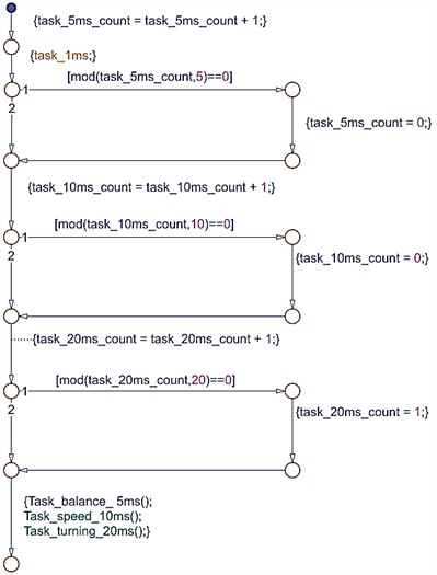
Fig. 7Modeling of the TWBMR upright balanced-loop control
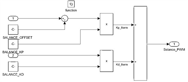
As shown in Fig. 7, the TWBMR upright balance angle loop modeling, when the MPU6050 gyroscope is placed stationary, there is a target balance state deviation constant BALANCE_OFFSET (the constant value is related to the zero position of the TWBMR machine); the target balance point and the difference between the target balance point and the KMP filtered angle, multiplied by the proportionality term of the coefficient BALANCE_KP, constitutes the PD control P term, Kp_Iterm. The angular velocity multiplied by the PD control differential coefficient BALANCE_KD constitutes the D term, Kd_Iterm, of the PD control. Multiply the angular velocity by the differential coefficient of the PD control BALANCE_KD to form the D term of the PD control Kd_Iterm. Then, superpose the P term and the D term to form the PWM duty cycle of the balancing loop PD control to provide the motor drive module. This completes the control of the robot's balance from upright to forward balance. The robot’s self-balancing tuning is done by adjusting the BALANCE_OFFSET, BALANCE_KP and BALANCE_KD parameters.
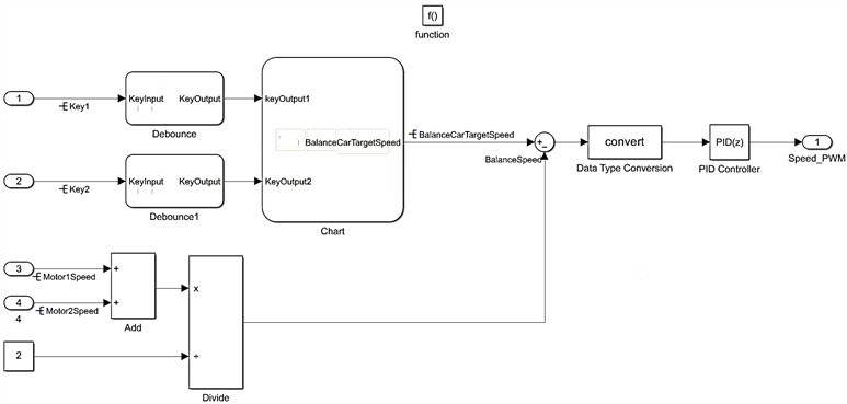
4.2.3. Speed-loop PI control and output
As shown in Fig. 8, the robot speed loop is modeled, and the target speed can be set by keystroke, Bluetooth communication, or microcontroller serial port command. The current motor speed is determined by reading the motor code pulse, and the left and right motor speeds are averaged to calculate the actual robot speed. According to the model, two key inputs are debounced and then entered into the PI operation.
Fig. 8Modeling of the TWBMR speed-loop control
4.2.4. Direction-loop PD control and output
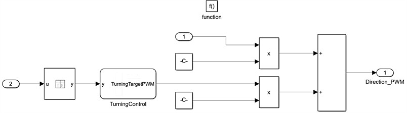
The TWBMR can either steer or rotate in place. If the target deflection angle is 0 when the robot is not steering, then it steers according to the actual value. See the direction loop PWM output shown in Eq. (6) multiplying the target deflection angle by the coefficient of the proportionality term, , constitutes the P term of the PD control, and multiplying the -axis gyroscope measurement data by the differentiation coefficient, , constitutes the term of the control:
The directional loop modeling is shown in Fig. 9, where the -axis gyro angular velocity and the left and right encoder pulse counts are used as the PD control input parameters, and the PWM duty cycle of the directional loop control is derived from the P and D terms composed of the truth table logic operation and the proportional and differential calculations to control the left and right motors to realize the steering, respectively.
According to whether there is an obstacle in front of the robot, ultrasonic sensor can be used as the direction loop control input for the robot to automatically steer after encountering an obstacle; considering that the direction control does not have high real-time requirements, it is set as a 20ms time slice scheduling task.
Fig. 9Modeling of the TWBMR directional-loop control
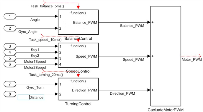
According to the TWBMR balance algorithm presented in Fig. 3, the three PID control variables of upright control, speed control, and direction control established above are added together, and then an offset is added to compensate for the mechanical static friction force of the car model. The output after the addition is saturated and used as the PWM duty cycle output. This ensures smooth and continuous control of the TWBMR system at all times, thereby enhancing the stability of the robotic system. Modeling of the TWBMR control system based on STM32-MAT as shown in Fig. 10.
Fig. 10The TWBMR control system model
4.3. Code generation
After establishing the TWBMR control model, it is essential to convert the designed model into a .c file, compile it in the Keil MDK environment, and subsequently download the program to the STM32 Microcontroller.
In the MATLAB/Simulink model editing environment, click the Simulink environment configuration button with the mouse, first set [Solver] to discrete mode and fixed step size, and then select “stm32.tlc” in [Browse] menu in the [Code Generation] menu.
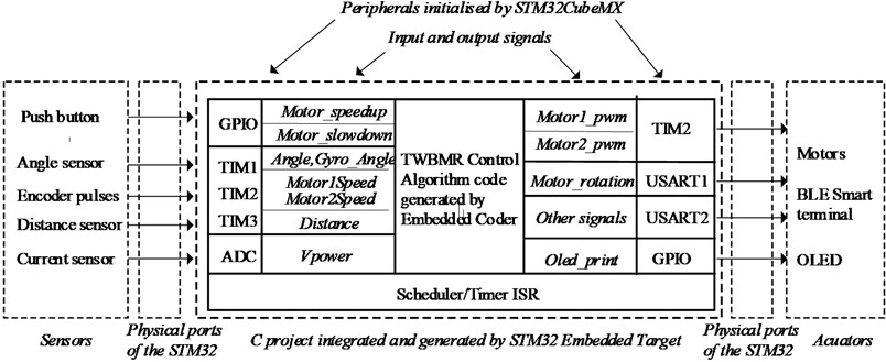
Fig. 11 illustrates the hierarchy and interface implementation of the entire generation project. This project encompasses control algorithms and their associated signals, which are connected to the microcontroller peripherals. The peripheral interfaces of the STM32 microcontroller are linked to external sensor components, including the TWBMR gyroscope and encoders, as well as execution hardware such as motors and human-machine interfaces.
The initialization of the pins, clock tree, and related peripherals of the STM32 microcontroller is implemented using the .ioc file generated by the STM32CubeMX software configuration. The STM32 microcontroller transmits sensor data to the BLE smart terminal via the Bluetooth master module connected to the USART2 serial port, while simultaneously receiving various control commands from the terminal application. Additionally, the STM32 microcontroller relays the real-time calculated PWM duty cycle to the two channels of timer TIM2, thereby achieving PID control of the TMBWR DC motor.
Compared with the traditional programming method of firmware libraries and registers, the C code project file mode generated by Simulink modeling is more convenient and efficient, and the automatic code generation of Simulink model development method makes the established algorithmic model and programming integrated, so the design environment is more unified and the testing and modification are more systematic.
Fig. 11The TWBMR project outline
5. Simulating and experimentally validating
5.1. Experimental methods and procedures
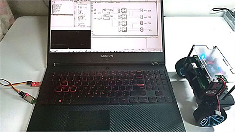
As illustrated in Fig. 12, the TWBMR employs the STM32F103 microprocessor as its control center. It gathers information regarding the robot's direction, attitude, and speed through the external MPU6050 three-axis attitude sensor and speed measurement. The 512-line encoder serves to determine the presence of obstacles through ultrasonic distance measurement, while the motor drive module facilitates motor operation through real-time PWM duty cycle value calculation by the microprocessor. Additionally, the BLE wireless transmission module enables motor operation and wirelessly facilitates communication between the robot and an intelligent terminal or host computer.
Fig. 12The hardware system
5.2. Attitude information acquisition
After the TWBMR embedded software is programmed with STM32 microprocessor Flash, the robot attitude data and control information can be collected and analyzed. During the experiment, the master-slave Bluetooth module was used to establish the wireless communication between the TWBMR and the Android terminal or PC. The STM32 microcontroller sent the information of the robot's inclination angle, angular speed and drive quantity to the serial port every 20 ms. After data collection by the upper computer (Android terminal or PC), it was further unpacked and analyzed.
The MPU6050 DMP converts the raw sensing data generated by the gyroscope directly into a quaternion output, which is more convenient for calculating the Euler angles to get yaw, roll, and pitch. using the built-in DMP greatly simplifies the design of the 4-axis code, and the MCU does not have to perform the attitude solving process, thus allowing more time to handle other events and this greatly reduces the burden on the MCU, leaving more time to process other events and improving the real-time performance of the system.
Fig. 13The TWBMR attitude information acquisition
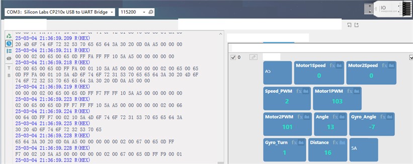
Wireless communication with the TWBMR is established based on the master-slave Bluetooth communication module and the upper computer serial port debugging tool, JCom. As shown in the robot attitude information acquisition in Fig. 13, JCom accurately parses and visualizes the data packets sent by the Bluetooth master module and acquires the left and right motor encoder counts and PWM outputs, gyro angle and steering angle, and ultrasonic distance. It is important to emphasize that the baud rate of Bluetooth communication module, STM32 serial port setting and JCom serial port tool must be consistent at 115200 bps.
5.3. PID tuning
Due to the implementation of the TWBMR parallel PID control, the vertical loop, speed loop, and steering loop are independently computed and subsequently weighted and superimposed to determine the final motor control output. The parameters of these three loops exhibit strong coupling; therefore, it is essential to prevent conflicts in control outputs by ensuring proper polarity alignment and parameter proportioning. The PID parameter tuning procedure is illustrated in Table 2.
Due to hardware reasons such as motor performance differences, sensor deviations and mechanical structure deviations, the PID parameters of the different TWBMR will always be different. It is the best practice to establish a parameter mapping table to record the optimal PID parameter combination under different hardware combinations and form a version management system.
The actual parameter adjustment can also be transmitted through Bluetooth angle, angular velocity, motor PWM waveform to visualize the data to observe the oscillation frequency and amplitude. The Android APP was used to modify the PID parameters in real time, and the parameter combination effect was quickly verified, so that the parameters were dynamically adjusted. After debugging, multi-scene verification such as slope, load and emergency stop is carried out to ensure the robustness of parameters.
The parameter tuning summarizes and sums up the abnormal phenomena and corresponding solutions as shown in Table 3.
Table 2The TWBMR parallel PID tuning flow
Phase | Steps and Operations | Key parameters and phenomena | Objectives and key points of handling |
Mechanical median calibration | 1. Tilt the car forward and backward to the critical tipping point, and record the angle values and 2. Calculate the median /2 and write it into the program | Real time angle display via serial port/OLED to ensure median error < 0.5° | Ensure that the upright ring reference angle is accurate |
Vertical ring polarity verification | 1. Only enable the upright ring PD control 2. Artificially tilt the car and observe the direction of wheel response 3. When polarity is incorrect, the wheel accelerates in reverse and tilts | polarity error: The car accelerates and tilts over polarity correct: wheel drive direction is consistent with tilt direction | Prioritize verifying polarity matching to avoid losing control during subsequent debugging |
Initial tuning of three loop parameters | 1. Vertical ring: increases from 40 until low-frequency oscillation occurs in the vehicle body 2. Speed loop: = 3-5, 0.1-0.3 3. Steering ring: = 1.0-2.068 | High of the upright ring: high frequency jitter of the body. The speed loop is too large: the motor output is abrupt. Steering ring too high: serpentine ride | The three loop parameters are synchronously fine-tuned to avoid coupling oscillation caused by too strong single loop parameters |
Dynamic balance optimization | 1. Add to the upright ring to suppress oscillation (range 2-5) 2.Superimposed low-pass filter for speed loop (cut-off frequency 5-10 Hz) 3. The steering ring introduces gyroscope -axis angular velocity compensation | deficiency: continuous low-frequency swing Insufficient filtering: motor high-frequency noise Missing steering compensation: body tilt over corners | The dynamic response and steady-state accuracy are balanced, and the sensor noise interference is suppressed |
Parameter co-optimization | 1. The ratio between vertical ring and speed ring is controlled at 10:1 (for example, = 100 vertical ring corresponds to = 10 speed ring). 2. The steering ring weight is set to 20 %-30 % of the upright ring output | Weight imbalance: upright instability during steering Proportional mismatch: external force interference recovery lag | Three-loop cooperative control is realized by parameter ratio to avoid control quantity conflict |
5.4. Real-time curve
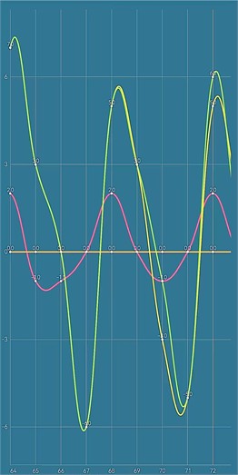
The TWBMR tilts under the influence of external forces while in balanced mode and achieves dynamic equilibrium through the implementation of self-balancing and motor drive algorithms. As illustrated in Fig. 14, a multi-channel real-time curves with a sampling period of 5 Hz are obtained. The red, green, and blue curves represent the left motor encoder pulse count, robot inclination angle, and angular velocity, respectively. The values at any time on the horizontal axis of the real-time curve correspond to the values captured and parsed by the serial port debugging tool JCom shown in Fig. 13.
Table 3PID tuning anomalies and solutions
Performance | Possible reasons | Solution |
The robot oscillates violently at high frequencies | The in the upright loop is too high/the is insufficient | Reduce and appropriately increase ; Check the delay of the gyroscope data |
Slow periodic swing | The accumulation of in the speed loop is excessive | Limit the upper limit of the integral term or add a low-pass filter |
Cannot be restored after being postponed by external force | The speed loop / is too small | Gradually increase the parameters of the velocity loop while observing the stability of the upright loop |
The vehicle body tilts more severely when turning | The steering ring is coupled with the upright ring | Reduce the of the steering loop or increase the differential term of the upright loop |
Fig. 14The TWBMR real-time curve
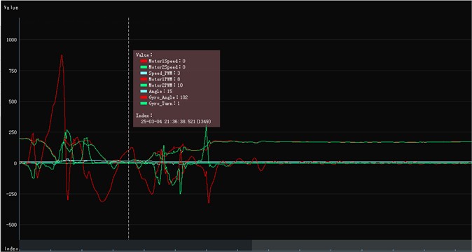
In the Fig. 14, at 5, 13, and 21 seconds, a positive force is applied to the TWBMR, causing it to temporarily lose balance and exhibit an inclination of less than 0.08 radians. It is evident that upon the application of external force, the angle value changes instantaneously. Following this, within the subsequent 3 seconds, a “hill-shaped” waveform appears due to the adjustments made by the self-balancing algorithm, ultimately stabilizing near the 0 value. Initially oscillating around the 0 value, the angular velocity experiences a significant change immediately upon the application of external force, remaining in a state of substantial fluctuation for approximately 3 to 4 seconds before eventually stabilizing near the 0 value.
These observations demonstrate that the TWBMR algorithm can effectively counteract external forces to a certain extent. In non-equilibrium states, the TWBMR can be re-balanced through the algorithm.
5.5. Android HCI
Android is an open-source operating system built on the Linux kernel and developed by Google [28]. It is the most prevalent smartphone operating system globally, widely utilized in mobile phones, tablets, wearable smart devices, and other domains [8]. The TWBMR application, developed for the Android platform, is capable of receiving, storing, and displaying real-time attitude information. Additionally, it facilitates control over the TWBMR motion and PID parameter adjustments, thereby enabling effective HCI.
The design of the TWBMR APP primarily encompasses four key components: Bluetooth communication design, communication instruction design, activity and service binding, and UI design. The Bluetooth communication design establishes a critical link for information transmission between the APP and the TWBMR. The communication instruction design formulates a protocol to facilitate data analysis between the TWBMR and the APP. The binding of activity and service enables seamless background data communication. To analyze and interpret various communication instructions and their meanings, a comprehensive communication protocol has been developed between the APP and the TWBMR, as illustrated in Fig. 15.
Fig. 15Communication instruction composition
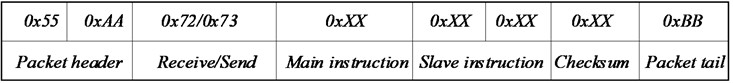
The data packet comprises eight bytes. The first two bytes, 0×55 and 0×AA, serve as fixed headers. The third byte is either 0×72 or 0×73, corresponding to the ASCII values for the characters and , respectively. These indicate whether the data packet is being transmitted from the TWBMR to the APP or from the APP to the robot. According to convention, only packets with these specific values are recognized as valid communication instructions. The fourth byte represents the primary instruction, while the fifth and sixth bytes constitute the secondary instruction. The seventh byte is the checksum value, and the eighth byte, 0×AA, serves as the fixed end-of-packet marker.
Table 4Communication instruction table
3rd byte | 4th byte | 5th and 6th bytes | Meaning of instruction |
0×72 | 0×01 | * | Left motor encoder count |
0×02 | * | Right motor encoder count | |
0×03 | * | Angle | |
0×04 | * | Angular velocity | |
0×05 | * | Left motor PWM | |
0×06 | * | Right motor PWM | |
0×07 | * | Distance | |
0×08 | * | Residual electricity | |
0×73 | 0×01 | – | Stop |
0×02 | mm | Forward | |
0×03 | nn | Back | |
0×04 | l | Left | |
0×05 | r | Right | |
0×06 | p | Setting the parameters | |
0×07 | i | Setting the parameters | |
0×08 | d | Setting the parameters |
The details and meaning of the associated communication instructions are shown in Table 4. When the 3rd byte is 0×72, the 4th main instruction is 0×01, the 5th byte and the 6th byte values represent the lower and upper octets of the motor encoder readings; when the 3rd byte is 0×73, the 4th main instruction is 0×02, the 5th byte and the 6th byte values represent the forward distance of the robot.
As shown in Fig. 16, the Android APP UI mainly includes homepage, waveform display, PID parameter adjustment and debugging page. Fig. 16(a) represents the status display and remote-control interface, in which the status display includes the left and right wheel encoder speed, tilt angle, battery remaining power display and command (data) debugging; the Bluetooth remote control supports gravity or keyboard mode to control the robot acceleration, deceleration, and forward, backward, left and right movements. When performing remote control operations, the instructions sent by each operation are displayed in the debug column. Fig. 16(b) is the real-time waveform display interface, the current three waveforms (the colors correspond to red, orange and yellow) represent the waveforms of the robot's Euler angle data in , and axes, respectively. The three data displayed on the waveform page are all from the DMP attitude output of the gyroscope: yaw, roll and pitch.
The PID parameter debugging interface supports up to 9 channels of data parameter adjustment, and supports the real-time setting of PID parameters of vertical loop, speed loop and direction loop. When each parameter adjusted slide rail slides, it will send data to the TWBMR; The debug page records the history of all communication processes.
Fig. 16Android APP UI
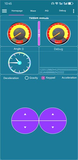
a) Attitude display and remote-control
b) Waveform display
6. Conclusions
This design is based on Matlab/Simulink MBD embedded software development method, with STM32 microcontroller as the core controller, using gyroscope and accelerometer to measure the tilt angle and acceleration of the balance vehicle, and realizing the self-balancing control of the TWBMR through the DMP attitude solving, PID control of the robot's upright loop, velocity loop and direction loop; based on the Bluetooth communication module and the Android APP, the robot status reading, remote control, waveform display and online parameterization are realized.
The TWBMR model-based embedded development methodology frees from the complex register programming of microcontrollers, and through graphical simple operation and configuration, it quickly and efficiently builds project models in Simulink/Stateflow, conceptualizes project solutions, and realizes automatic generation of product C code, which greatly reduces the threshold of embedded system development, improves the transplantation efficiency, and reduces the development cost.
It is experimentally verified that the TWBMR has the advantages of fast response speed, high sensitivity and strong anti-interference ability while realizing the functions of fast upright walking, steering and maintaining balance; it can accurately send and receive data through Bluetooth, with high control accuracy, good system stability and fast time response.
Future research should prioritize the optimization of control algorithms and Android interaction. Specifically, this includes pursuing a dual-state estimation strategy that combines Kalman filtering with particle filtering to enhance the accuracy of pose solutions. Additionally, efforts should focus on investigating reinforcement learning-driven LQR algorithms for real-time parameter adjustment in dynamic environments. Furthermore, integrating data from Android smartphone sensors (GPS/IMU) with vehicle-mounted LiDAR can be explored to construct a SLAM-based navigation system. The development of an ARCore-based virtual control interface should also be pursued to enable gesture and head posture control for mobile phone cameras. Subsequently, researching the TWBMR AI edge computing and cluster collaboration is recommended, where multi-robot collaborative control can be achieved by leveraging BLE Mesh technology, with the Android device serving as the cluster scheduling center. Finally, the exploration of ultra-high-speed control responses driven by bionic structures and quantum computing in real-time applications should be conducted.
References
-
Astrom, K. J., R. E. Klein, and A. Lennartsson, “Bicycle dynamics and control: adapted bicycles for education and research,” IEEE Control Systems, Vol. 25, No. 4, pp. 26–47, Aug. 2005, https://doi.org/10.1109/mcs.2005.1499389
-
U. Nagarajan, G. Kantor, and R. Hollis, “The ballbot: An omnidirectional balancing mobile robot,” The International Journal of Robotics Research, Vol. 33, No. 6, pp. 917–930, Nov. 2013, https://doi.org/10.1177/0278364913509126
-
B. Nail, A. Kouzou, and A. Hafaifa, “Digital Stabilizing and Control for Two-Wheeled Robot,” Studies in Systems, Decision and Control, pp. 237–253, Jan. 2019, https://doi.org/10.1007/978-981-13-2212-9_11
-
I. Aldarraji, A. A. Kakei, A. G. Ismaeel, G. Tsaramirsis, and A. Patel, “Dynamics modeling and motion simulation of a segway robotic transportation system,” in Lecture Notes in Electrical Engineering, Singapore: Springer Nature Singapore, 2022, pp. 83–91, https://doi.org/10.1007/978-981-19-0252-9_9
-
Dinh Ba Pham et al., “Balancing and transferring control of a ball segway using a double-loop approach [applications of control],” IEEE Control Systems, Vol. 38, No. 2, pp. 15–37, Apr. 2018, https://doi.org/10.1109/mcs.2017.2786444
-
I. Siradjuddin et al., “Stabilising a cart inverted pendulum with an augmented PID control scheme,” in MATEC Web of Conferences, Vol. 197, p. 11013, Sep. 2018, https://doi.org/10.1051/matecconf/201819711013
-
A. T. Ali, A. M. O. Mohamedy, A. S. A. Salimz, E.-A. O. M. El-Aminx, and O. M. K. Ahmed, “Design and implementation of two-wheeled self-balancing robot using PID controller,” in International Conference on Computer, Control, Electrical, and Electronics Engineering (ICCCEEE), pp. 1–5, Feb. 2021, https://doi.org/10.1109/iccceee49695.2021.9429579
-
B. Sawatzky, I. Denison, S. Langrish, S. Richardson, K. Hiller, and B. Slobogean, “The Segway personal transporter as an alternative mobility device for people with disabilities: a pilot study,” Archives of Physical Medicine and Rehabilitation, Vol. 88, No. 11, pp. 1423–1428, Nov. 2007, https://doi.org/10.1016/j.apmr.2007.08.005
-
S.-T. Kao and M.-T. Ho, “Balance control of a configurable inverted pendulum on an omni-directional wheeled mobile robot,” Applied Sciences, Vol. 12, No. 20, p. 10307, Oct. 2022, https://doi.org/10.3390/app122010307
-
M. Tesfay and R. Weldegiorgis, “Dynamic modelling and design of hierarchical sliding mode control for a two-wheeled self-balancing mobile robot moving on a muddy road,” Authorea, Aug. 2024.
-
C. Badgujar and S. Mohite, “Design, analysis and implementation of control moment gyroscope (CMG) mechanism to self-balance a moped bike,” Materials Today: Proceedings, Vol. 72, pp. 1517–1523, Jan. 2023, https://doi.org/10.1016/j.matpr.2022.09.380
-
W. Zhai, L. Dong, and Y. Hu, “Self-tuning control of steam sterilizer temperature based on fuzzy PID and IPSO algorithm,” Journal of Measurements in Engineering, Vol. 12, No. 4, pp. 638–655, Dec. 2024, https://doi.org/10.21595/jme.2024.24134
-
Y. Ma, F. Meng, and S. Xiong, “Design and implementation of a two-wheeled self-balancing car using a fuzzy Kalman filter,” Applied Sciences, Vol. 14, No. 12, p. 5296, Jun. 2024, https://doi.org/10.3390/app14125296
-
W. Zhai, Y.-L. Hu, and F. Ran, “CQPSO scheduling algorithm for heterogeneous multi-core DAG task model,” Modern Physics Letters B, Vol. 31, No. 19-21, p. 1740050, Jul. 2017, https://doi.org/10.1142/s0217984917400504
-
T. A. Mai, D. N. Anisimov, T. S. Dang, and N. Dinh, “Development of a microcontroller-based adaptive fuzzy controller for a two-wheeled self-balancing robot,” Microsystem Technologies, Vol. 24, No. 9, pp. 3677–3687, Mar. 2018, https://doi.org/10.1007/s00542-018-3825-2
-
N. M. Mohd Noor, S. A. A. Mohd Halid, and R. Mahmod @Wahab, “Study the performance of two-wheeled balancing mobile robot using fuzzy PD controller,” Jurnal Mekanikal, pp. 164–174, Nov. 2023, https://doi.org/10.11113/jm.v46.500
-
T. Zhao, Q. Yu, S. Dian, R. Guo, and S. Li, “Non-singleton general type-2 fuzzy control for a two-wheeled self-balancing robot,” International Journal of Fuzzy Systems, Vol. 21, No. 6, pp. 1724–1737, Jun. 2019, https://doi.org/10.1007/s40815-019-00664-4
-
L. Chen et al., “Robust hierarchical sliding mode control of a two-wheeled self-balancing vehicle using perturbation estimation,” Mechanical Systems and Signal Processing, Vol. 139, p. 106584, May 2020, https://doi.org/10.1016/j.ymssp.2019.106584
-
L. Guo, S. A. A. Rizvi, and Z. Lin, “Optimal control of a two‐wheeled self‐balancing robot by reinforcement learning,” International Journal of Robust and Nonlinear Control, Vol. 31, No. 6, pp. 1885–1904, Jul. 2020, https://doi.org/10.1002/rnc.5058
-
C. Acar and T. Murakami, “A robust control of two-wheeled mobile manipulator with underactuated joint by nonlinear backstepping method,” IEEJ Transactions on Industry Applications, Vol. 130, No. 6, pp. 742–751, Jan. 2010, https://doi.org/10.1541/ieejias.130.742
-
Ching-Chih Tsai, Hsu-Chih Huang, and Shui-Chun Lin, “Adaptive neural network control of a self-balancing two-wheeled scooter,” IEEE Transactions on Industrial Electronics, Vol. 57, No. 4, pp. 1420–1428, Apr. 2010, https://doi.org/10.1109/tie.2009.2039452
-
S. A. Trefilov and G. V. Khodyrev, “Development of a mathematical model of a highly maneuverable robot for simulation of robots with different types of designs,” Vestnik IzhGTU Imeni M.T. Kalashnikova, Vol. 27, No. 3, pp. 38–48, Oct. 2024, https://doi.org/10.22213/2413-1172-2024-3-38-48
-
S. Kim and S. Kwon, “Dynamic modeling of a two-wheeled inverted pendulum balancing mobile robot,” International Journal of Control, Automation and Systems, Vol. 13, No. 4, pp. 926–933, May 2015, https://doi.org/10.1007/s12555-014-0564-8
-
E. Ataç, K. Yildiz, and E. E. Ülkü, “Use of PID control during education in reinforcement learning on two wheel balance robot,” Gazi Üniversitesi Fen Bilimleri Dergisi Part C: Tasarım ve Teknoloji, Vol. 9, No. 4, pp. 597–607, Dec. 2021, https://doi.org/10.29109/gujsc.955562
-
T. A. Mai, T. S. Dang, H. C. Ta, and S. P. Ho, “Comprehensive optimal fuzzy control for a two-wheeled balancing mobile robot,” Journal of Ambient Intelligence and Humanized Computing, Vol. 14, No. 7, pp. 9451–9467, Apr. 2023, https://doi.org/10.1007/s12652-023-04613-w
-
L. L. Souza and M. H. N. França, “Design, manufacturing and testing of a two-wheeled self-balancing robot,” Journal of Bioengineering, Technologies and Health, Vol. 7, No. 1, pp. 37–42, May 2024, https://doi.org/10.34178/jbth.v7i1.364
-
O. M. Mohamed Gad, S. Z. M. Saleh, M. A. Bulbul, and S. Khadraoui, “Design and control of two wheeled self balancing robot (TWSBR),” in Advances in Science and Engineering Technology International Conferences (ASET), pp. 1–6, Feb. 2022, https://doi.org/10.1109/aset53988.2022.9735004
-
O. C. Karaduman, S. Kaygisiz, A. Buldu, K. Yildiz, and D. Cetinol, “Developing a security software for android-based systems (“Secand”),” The Anthropologist, Vol. 17, No. 1, pp. 37–43, Oct. 2017, https://doi.org/10.1080/09720073.2014.11891412
-
A. Acar et al., “An android application for teaching android operating system,” in International Conference on Electrical, Computer, Mechanical and Mechatronics Engineering, 2015.
Cited by
About this article

This work is sponsored by 2022 Qing Lan Project in Jiangsu Province of China and research project on higher education reform in Jiangsu Province under Grant No. 2023JSJG226.
The datasets generated during and/or analyzed during the current study are available from the corresponding author on reasonable request.
Wenzheng Zhai: study conception and design, data collection, analysis and interpretation of results, draft manuscript preparation. Liangwei Dong: study conception and design.
The authors declare that they have no conflict of interest.
