Abstract
The profundity of the extant technical exploits on the design of controllers for automatic voltage regulation (AVR) systems is enormous. Several approaches that involve the deployment of a proportional integral derivative (PID) controller and its variants have proven to offer great plausibility. Despite the performance and simplicity of the PID controller on the AVR system, the existence of overshoots is inherent in the design, which is detrimental to the safety of power equipment. This paved the way for the introduction of a stabilizing loop on the AVR system to strategically minimize the oscillations due to overshoots. In general, most stabilizing loops are characterized by filter with preselected gains which are often arbitrarily selected and not intelligently incorporated into the existing AVR architecture. This paper presents an AVR system with a tunable stabilizing loop. The essence of this is to intelligently enhance the performance of the PID controller in terms of overshoot reduction and reduce the sensitivity of the system to variation of parameters in an optimal fashion. The optimality of the design is realized by deploying some metaheuristic algorithms (Snake Optimizer (SO), Gazelle Optimization Algorithm (GOA), Smell Agent Optimization (SAO), Pelican Optimization Algorithm (POA), Dandelion Optimization Algorithm (DOA) and American Zebra Optimization (AZOA)), on a set of well-posed constraints to deduce the best combination of values of the parameters of the PID and the adjustable gain of the stabilizing loop, while the integral time absolute error (ITAE) is used as the cost function. Comparative analyses of the performance of this design topology with that of a PID-based design without a stabilizing loop reveal that the proposed design offers a significant reduction in percentage overshoot. More so, the credibility and suitability of the smell agent optimization algorithm (SAO) and the pelican optimization algorithm (POA), among the deployed algorithms, in ascertaining zero overshoot were justified. Furthermore, the robustness analysis was made on the developed design to reveal and ascertain its level of insensitivity to parameter variation.
Highlights
- A PID controller-based AVR system often suffers increased oscillations due to the presence of overshoot, which poses a threat to the safety of power equipment.
- The introduction of an inner stabilizing loop eliminates or reduces the overshoots; however, earlier designs use a preselected low-pass filter, which leaves extra cost burdens.
- A proportional controller with a tunable gain is introduced in the stabilizing loop for the elimination of overshoot in the safest economic sense.
- Some metaheuristic algorithms were used to optimally obtain the gains of the PID controller and the tunable stabilizing gain; SAO and POA-based designs excellently eliminate the overshoots.
- The robustness of the design to changes in the parameters of the AVR system was justified.
1. Introduction
The essence of supplying power at a defined voltage cannot be over-emphasized. In reality, varying load conditions and many unpredictable realities often frustrate the supply of power at specified voltages; this causes negative economic value to designs and investment in power supply. This characterized voltage deviation from the reference value often leads to loss of power quality, which paved the way for the development of the automatic voltage regulator (AVR) system. An AVR system is used for maintaining the value of power supply voltage at a specified value for safe utilization at the receiving end [1-3]. The AVR system works in a feedback loop fashion to ensure a stable value of the output voltage. However, the effects of growing uncertainties, oscillations and prevailing load conditions affect the dynamic performance of an AVR system. Hence, controllers are used to improve the dynamic performance of an AVR system [4]. The most common and simplest controller that has been used in the AVR system is the proportional-integral-derivative controller (PID) controller [5, 6]. More so, many of its variants like the fractional-order PID (FOPID) controller, fractional-order PID with second-order derivative term (FOPIDD2) controller, PID with filter (PID-F) controller etc. have been used in the AVR system [4, 7, 8]; each of these gives varying level of performance with respect to stability and robustness but poses significant cost implications. Apart from PID controllers, basic and intelligent fuzzy logic controllers, adaptive controllers, robust controllers, predictive and data-driven AVR controllers etc. among others, have been used [9-17].
In tuning the values of the gains of the PID controller and its variants for optimal performance, many intelligent optimization algorithms have been deployed. Some of these algorithms are particle swarm optimization (PSO) algorithm [18-20], tree seed algorithm (TSA) [21], grasshopper optimization algorithm (GOA) [22], cuckoo search algorithm (CSA) [23], antlion optimizer [24], etc. among others. The significances of these algorithms are revealed in the outcomes of the simulations. All algorithms have different convergent characteristics and complexity, which also account for cost implications. However, the validity of the No-Free-Lunch theory and the quest for better performance necessitates the emergence and deployment of some other meta-heuristic algorithms.
In this paper, the necessity and the uniqueness of control action on the input to the generator of an AVR system is presented. Here, an optimized PID-based controller for an AVR system with a pre-generator proportional feedback loop is designed. The purpose of the deployment of this topology is to enhance the robustness and performance of the AVR system with respect to overshoot reduction. Here, four gain parameters were tuned for optimal performance by using some metaheuristic algorithms which are the snake optimizer (SO), the gazelle optimization algorithm (GOA), the smell agent optimization algorithm (SAO), the dandelion optimization algorithm (DOA), the pelican optimization algorithm (POA) and the American zebra optimization algorithm (AZOA) [25-27]. Comparative analyses of the performances of the deployed metaheuristic algorithms were made to ascertain the one with superior performance in terms of overshoot reduction. Furthermore, the performance of this design was compared with the existing PID-based AVR system without a stabilizing loop. A robustness analysis of the design in terms of sensitivity to parameter variation is presented to justify its feasibility as a solution for the control problem. Conclusively, the uniqueness and novelty of this research is the inclusion of the proportional controller, whose gain is tunable, in the inner stabilizing loop. This offers better simplicity in the safest economic sense and reduces the loss of some model peculiarities, unlike the use of a filter in the stabilizing loop. More so, only a little attention has been drawn by researchers to address the effects of overshoot in the AVR system. The rest of the paper is presented thus: Section II is a brief review of existing literature on the AVR system. In section III, the methodology for this approach is fully explained. The simulation results of the design and discussion are presented in section IV, while in V, the summary and recommendations for further works are stated.
2. Literature review
The justification of power quality is inherent in the ability to ensure a balance of reactive power. To minimize the degradation of power quality and voltage deviation in the work of [6], a PID controller was used to improve the performance of an AVR system with a stabilizer loop, which was made up of a filter. The conditions of stability were investigated to ascertain the permissible values of the proportional constant. Also, other gain values were arbitrarily selected to obtain the desired result. However, apart from the extra cost implications posed by using the filter in the stabilizer loop, optimal values of the gains could not be ascertained by arbitrary selection; the use of optimization algorithms would have guaranteed better and optimal dynamic performance. In [3], an AVR system was designed to obtain a regulated voltage by using an autotransformer, step-down transformer, a converter, inverter, comparator, relay switches and logic circuit. Here, the reference voltage was converted to its DC reference equivalent to serve as input to the comparator while the logic circuit yielded the control signal through the relay switches to the appropriate tap of the autotransformer to obtain the design specifications and give high precision and hysteresis. However, modelling of the components for dynamic response and comparative analyses with existing approaches were not considered. A novel PID plus second-order derivative controller was used in the research paper presented by [2] to improve the AVR system’s robustness. To obtain the optimal value of the four gains of the controller, the particle swarm optimization (PSO) algorithm was deployed and comparative analyses of the results using different optimization algorithms and FOPID were made; the superior performance of this approach in terms of robustness was justified with digital implementation of the simulation. Similarly, as in the work of [2], a variant of Runge-Kutta optimizer with Bode reference model was utilized to obtain the optimal values of the four gains in the AVR design. On an AVR system with excitation limiters to prevent windup, a FOPID controller was deployed to improve the robustness of the AVR system in the work of [8]. Ant colony optimization (ACO) algorithm and genetic algorithm (GA) were used to obtain the optimal values of the controller gains. The superior performance of the FOPID controller on the AVR system over the PID was ascertained on simulation as indicated by the steady-state response analysis. An approach towards obtaining the optimal PID-based AVR system by using Routh’s criteria analysis was presented by [5]. The values of the tolerable proportional gain on the premise of satisfying Routh’s criteria were used as a basis for obtaining the values of the other gains for PID configuration. The optimality of this approach would have been more significant if the allowable values of the proportional constant were used to formulate a well-posed optimization problem that can be solved by deploying an intuitively selected metaheuristic algorithm. By taking advantage of the number of poles, the sum of damping ratios and the integral time absolute error, in the paper presented by [1], an adjusted cost function was used to obtain the optimal parameters of a PID controller for an AVR system. Here, a symbiotic organisms search optimization algorithm was deployed to achieve a minimized cost function. The plausibility of this approach is hampered by the inherent tradeoff between stability and transient characteristics of the system. A linear model of the AVR and extended policy iteration quadratic tracking (PIQT) was used to design an adaptive optimal controller for an AVR system on the premise of the ideality of the sensors. The simulation results demonstrated a practicable implementation of the presented approach on the power system, albeit its performance relies on the fast dynamics of the sensors. In [29], in a similar fashion as in the work of [6], a PID controller was deployed to control an AVR system with a flexible stabilizing loop. The significance of using a stabilizing loop with PID was ascertained by comparative analysis with the performance of the system without a stabilizing loop. The results indicate a superior performance of the system with a stabilizing filter, however, the rigour of manually selecting the gains of the PID and that of the stabilizing loop based on Routh’s stability approach is much and may never yield optimality. Moreover, the computational burden imposed by having a filter in the stabilizing loop has serious cost implications. By taking a combination of different cost functions which include some of the system transient characteristics, a PID-based AVR system is presented by [21], and the tree seed algorithm (TSA) was deployed to obtain the optimal values of the PID gains. The significance of this proposed approach for regulating the terminal voltage of a synchronous generator was investigated and affirmed by robustness analysis. To address the derivative kick effect, a PID controller with a filtering element at the derivative end (PID-F) was presented by [7]. Here, a low pass filter was used, and a symbiotic organisms search algorithm was deployed to obtain the optimal gains of the controller and the low pass filter. The robustness of the design was investigated and confirmed by comparative analyses with other similar approaches without filters and also by the improved transient characteristics. In [30], a memorizable-SFA was proposed and deployed on a FOPID-based controller for the AVR system. The optimal values of the gains of the controller were obtained using a cost function which encompasses some transient characteristics of the system. The superior performance of the developed MSFA on the FOPID-based AVR system was revealed by comparative analyses of its results with those of similar algorithms. Interestingly, by utilizing the adaptive local search and experience-based perturbed learning strategy on the existing artificial rabbit optimization algorithm in [4], a modified rabbit optimizer was developed to eliminate the problem of local optima. The modified algorithm was deployed to fine-tune the gains of a FOPID controller with a second-order derivative controller (FOPIDD2) for the AVR system. The stability and robustness of this design topology were justified by comparative analyses and investigations of the dynamic and transient characteristics. Despite the plausibility of the myriads of intelligent FOPID-based controllers, the burden imposed by the cost of implementation is enormous, which can be of concern to designers or process engineers. Without loss of technical sanity and target, while retaining the feasibility of design, this paper presents a PID-based controller for an AVR system with an adjustable proportional controller in the inner stabilizing loop. The essence of this configuration is to achieve system robustness, in terms of overshoot reduction, in the safest sense. To obtain the gains of the PID and that of the stabilizing loop, six metaheuristic algorithms were deployed: SO, SAO, GOA, POA, DOA and AZOA. The GOA was inspired by the struggle for escape and survival by the gazelle in the environment of the predator [26]. The SAO was formulated based on the ability of a smell agent to perceive and detect molecules of smell [31]. The SO was developed based on the premise of the struggles and competitions among male snakes for food and for best mating partners [25]. The POA was inspired by the hunting behaviour of the pelicans when searching for food [32]. The DOA was developed by mimicking the flight nature of the dandelion seeds due to the wind [33]. The AZOA was formulated based on the social and leadership styles of the American zebra where the baby zebra leaves its herd before maturity and gets attached to another different herd that has no social tie with it [34].
The dynamic and steady-state characteristics of the system on simulation reveal the suitability of this proposed design for the regulation of the terminal voltage of a synchronous generator. Furthermore, comparative analyses of results obtained by deploying each of the algorithms were made. The robustness of this design in terms of insensitivity to parameter variation was presented. The next section reveals the design configuration and modelling.
3. Proposed design
The proposed control approach for the AVR system is depicted in Fig. 1. Here, another degree of freedom is imposed by the proportional action at the stabilizing loop which is nested with the PID controller. The essence of this ranges from the basics of simplicity of this design to the elimination of inherent oscillations and undesirable effects that are associated with the amplifying and the exciting components of the AVR system. Hence, superior power quality coexists with the economic benefits of a fast regulation of the terminal voltage of the generator in this presented topology.
Fig. 1Proposed AVR controller with stabilizing loop
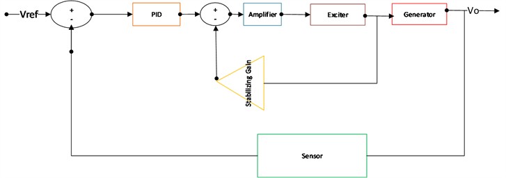
The mathematical modelling of the AVR system is obtained from the modelling of the component systems, that is the amplifier, exciter, generator, sensor and the stabilizing gain. Each of these are discussed in sub-sections.
a) Model of the Amplifier. The transfer function model of the amplifier is expressed in Eq. (1) [29]:
where, is the amplifier’s gain and is its time constant.
b) Model of the exciter. Without making attempt to reinvent the wheel, the following model of the exciter is expressed as transfer function and stated thus [29]:
where is the exciters gain while is the exciter’s time constant.
c) Model of the generator. The generator’s transfer function model is expressed accordingly as thus [28]:
where is the generator’s gain and is its time constant.
d) Model of the sensor. The sensor transfer function model is expressed in Eq. (4) [29]:
where is the sensor’s gain and is the sensor’s time constant.
e) Model of the stabilizing proportional controller. The proportional controller for the stabilizing loop is modelled by a proportional constant as expressed in Eq. (5):
f) Model of the PID controller. The general transfer function model of the PID controller is expressed in Eq. (6):
where , , and are the proportional, integral and the derivative gains of the PID respectively.
By considering the stated hydropower plant in the work of Zaw [29], and the established range of feasible values of for marginal stability, the following are the typical range of values of the parameters of the model:
– Amplifier: 10 40, 0.02 s 0.1 s.
– Exciter: 1 2, 0.4 s 1 s.
– Generator: 0.7 1, 1 s 2 s.
– Sensor: 0.02 1, 0.01 s 2.2 s.
The essence of the design is to track the terminal voltage of the generator irrespective of the load variation, disturbances and uncertainties. Here, an integral time absolute error is used as a cost function. The well-posedness of the optimization problem helps to achieve the best combinations of , , and for optimal tracking of the terminal voltage of the synchronous generator.
The values of the selected generator’s parameters are as follows:
– Gain constant of the amplifier, 10.
– Time constant of the amplifier, 0.1 s.
– Gain constant of exciter = 1.
– Time constant of exciter = 0.4 s.
– Gain constant of generator = 1.
– Time constant of generator = 1 s.
– Gain constant of sensor = 1.
– Time constant of the sensor = 0.01 s.
The simulation of the presented design was done on MATLAB 2020b. A robustness check and analysis of the presented design were executed with respect to variations in the amplifier’s and exciter’s parameters. In the next section, details of the results are presented, and analyses are discussed by examining the following transient characteristics: rise time (), settling time (), peak time (), and percentage overshoot (% ).
4. Simulation results and discussion
In order to obtain the optimal values of the gains of the PID controller and the adjustable gain of the inner stabilizing loop, the following metaheuristic algorithms are used: Snake Optimizer (SO), Smell Agent Optimization (SAO) algorithm, American Zebra Optimization Algorithm (AZOA), Dandelion Optimization (DO) algorithm, Gazelle Optimization Algorithm (GOA) and Pelican Optimization Algorithm (POA). The ranges of values for the gains were set between 0.1 and 10.
The values of the optimal gains of the PID and the tunable inner stabilizing loop, using the integral time absolute error as the cost function, for each case of the deployed optimization algorithms are presented in Table 1.
Table 1Optimized gains of the controller with stabilizing loop for AVR system
Optimization algorithm | ||||
SO | 6.5822 | 5.4193 | 1.3808 | 0.5675 |
SAO | 9.0578 | 9.0673 | 1.3572 | 9.1424 |
AZOA | 6.9901 | 5.7922 | 1.2945 | 0.65314 |
DOA | 6.2502 | 5.0906 | 1.4179 | 0.52129 |
GOA | 6.1715 | 5.0051 | 1.4266 | 0.51032 |
POA | 6.1793 | 5.0022 | 1.4266 | 0.5110 |
From Table 1, it can be inferred that for each case of the deployed algorithms on the proposed AVR system with tunable stabilizing loop, optimal regulation of the AVR system requires more of proportional and integral actions than the derivative actions. In an excellent fashion, the gain of the tunable loop for optimal AVR regulation is less than unity for all cases of the except for the SAO whose gain is significantly high. The Fig. 2, which shows the step response of the AVR system, reveals certain unique behaviours of the algorithms’ performances.
In Fig. 2, for a step input of the input, the AVR system could track the generator’s terminal voltage on the deployment of each algorithm. More so, the POA and SAO algorithm-tuned AVR systems exhibit sameness of dynamic trajectory with a unique performance of zero overshoot. The reduced overshoot is anticipated by the longest rise times and peak times compared to the other deployed optimization algorithms. This achievement of zero overshoot is an indication of the elimination of oscillations. This guarantees the safety of power equipment and reduces maintenance burden.
Fig. 2Step response of the AVR system with tunable stabilizing loop
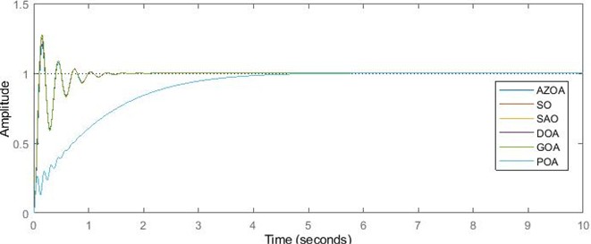
The GOA-tuned AVR system possesses the smallest rise time which is technically implicated in the corresponding highest value of percentage overshoot as revealed in Table 2. In terms of achieving stability in the shortest time, the AZOA-tuned AVR system outperformed others, but at an infinitesimal margin when compared to those of SO, DOA and GOA. In this way, it takes the least control effort to achieve stability in the AZOA-tuned AVR system.
Table 2Transient characteristics of the PID-based AVR system with stabilizing loop
Optimization algorithm | (s) | (s) | (s) | % (%) |
SO | 0.0694 | 1.2192 | 0.1456 | 25.0883 |
SAO | 2.433 | 3.8539 | 6.8634 | 0.0893 |
AZOA | 0.0724 | 1.2177 | 0.1605 | 20.7455 |
DOA | 0.0683 | 1.2239 | 0.145 | 26.9208 |
GOA | 0.0681 | 1.2253 | 0.1458 | 27.3597 |
POA | 2.433 | 3.8539 | 6.8634 | 0.0893 |
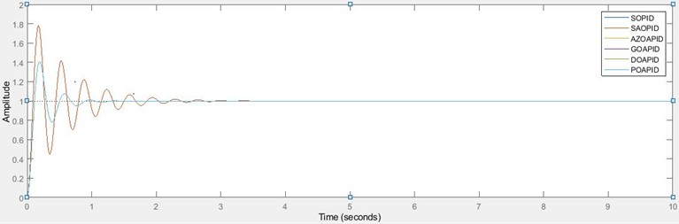
The PID controller, despite its plausibility as an on-the-go control approach, sometimes poses a little setback depending on the nature of the control plants and constraints as initially discussed in the literature. Table 3 reveals the values of the optimal gains of the PID and the transient characteristics of a PID-based AVR system without a stabilizing loop when subjected to a unit step signal for each of the deployed algorithms. More so, the step response of the PID-based AVR system without a stabilizing loop is depicted in Fig. 3.
Table 3Optimal gains of controller and the transient characteristics of PID-based AVR system without a stabilizing loop
Optimization algorithm | (s) | (s) | (s) | % (%) | |||
SO | 2.5917 | 1.7572 | 1.131 | 0.077 | 0.8548 | 0.1892 | 40.6402 |
SAO | 8.7409 | 9.0673 | 1.3837 | 0.0611 | 2.1518 | 0.1754 | 78.3218 |
AZOA | 2.5917 | 1.7572 | 1.131 | 0.077 | 0.8548 | 0.1892 | 40.6402 |
DOA | 2.595 | 1.758 | 1.1308 | 0.077 | 0.8548 | 0.1892 | 40.6623 |
GOA | 2.59902 | 1.75795 | 1.13071 | 0.077 | 0.8549 | 0.1893 | 40.6915 |
POA | 2.5917 | 1.7573 | 1.131 | 0.077 | 0.8548 | 0.1892 | 40.6405 |
The unique convergence of the deployed algorithms, except for SAO, in achieving the same optimal values of PID controller gains is profound as revealed in Table 3 and Fig. 3. In addition, the significance of the PID controller in the AVR system without an inner stabilizing loop is exemplified. As revealed in the settling times, it took less effort for the AVR system without stabilizing loop to achieve perfect tracking of the terminal voltage of the regulator in each case of the deployed algorithms except for SAO; however, the inherent higher overshoot in the system, with SAO-based as highest, is much when compared to the AVR system with a stabilizing loop. This poses a technical and economic burden due to the potentially devastating effects of oscillations on the power equipment and measuring instruments. This marks the essentialities of adopting the developed AVR system with a tunable stabilizing loop. For the proposed design, SAO and PAO algorithms offer superior performance in the cancellation of overshoot by incorporating the tunable proportional gain into the stabilizing loop in the AVR system.
Fig. 3Step response of PID-based AVR system without the stabilizing loop
The work circumvents the necessity to ascertain the robustness of the design in terms of sensitivity to variation of parameters. In the first instance, the presented design is subjected to changes in the variation of amplifier parameters; that is, for a 25 % and 50 % increase in amplifier’s gain and a corresponding percentage reduction in amplifier’s time constant. The basis for variation of parameters was confined within the operating specifics of each AVR sub-unit of the mentioned plants, which has been initially stated in the methodology; the results of the transient characteristics of the system when step response was applied in each case are depicted in Table 4 and Table 5.
Table 4Characteristics of the AVR system with respect to variation in amplifier’s gain
Percentage increase in (%) | Optimization algorithm | (s) | (s) | (s) | % (%) |
25 | SO | 0.0603 | 1.3457 | 0.1307 | 29.3665 |
SAO | 2.4323 | 3.8486 | 6.4087 | 0.0798 | |
AZOA | 0.0630 | 1.3420 | 0.1309 | 24.2818 | |
GOA | 0.0590 | 1.3506 | 0.1309 | 32.0655 | |
DOA | 0.0592 | 1.3494 | 0.1308 | 31.544 | |
POA | 2.4323 | 3.8486 | 6.4087 | 0.0798 | |
50 | SO | 0.0538 | 1.4726 | 0.1197 | 32.9685 |
SAO | 2.4321 | 3.8452 | 6.1208 | 0.0586 | |
AZOA | 0.0563 | 1.4688 | 0.1198 | 27.3568 | |
GOA | 0.0526 | 1.4771 | 0.1199 | 36.0243 | |
DOA | 0.0528 | 1.4760 | 0.1199 | 35.4339 | |
POA | 2.4321 | 3.8452 | 6.1208 | 0.0586 |
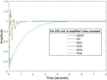
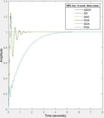
For the 25 % and 50 % increase in the amplifier’s gain, the designed AVR system with a tunable stabilizing loop shows marked robustness in terms of performance and stability as illustrated in Fig. 4. For the 25 % increase in the amplifier’s gain, the rise time approximately decreases by 13 % for each of SO, AZOA, DOA and GOA, and decreases by 0.03 % for each of SAO and POA. The settling time approximately increases by 10 % for each of SO, AZOA, GOA and DOA while it decreases by 0.1 % for each of SAO and POA. The peak time approximately decreases by 10 % for each of SO, GOA and DOA, decreases by 7 % for each of SAO and POA and also decreases by 18 % for AZOA. The percentage overshoot approximately increases by 17 % for each of SO, AZOA, GOA and DOA while it decreases by 12 % for each of SAO and POA. For the 50 % increase in amplifier’s gain, the rise time approximately decreases by 22 % for each of SO and AZOA, decreases by 0.04 % for each of SAO and POA, and decreases by 23 % for each of GOA and DOA. The settling time approximately increases by 21 % for each of SO, AZOA, GOA and DOA while it decreases by 0.2 % for each of SAO and POA. The peak time approximately decreases by 18 % for each of SO and GOA, decreases by 11 % for each of SAO and POA, decreases by 25 % for AZOA and also decreases by 17 % for DOA. The percentage overshoot approximately increases by 31% for SO, increases by 32 % for each of AZOA, GOA and DOA, while it decreases by 34 % for each of SAO and POA. The indication of this percentage variations implies that the presented design offers low sensitivity to variation of amplifier’s gain. It is appreciable to observe the unique performances of the SAO and the POA in ensuring zero overshoot even in the presence for variation of parameters. Hence, the safety of the power equipment cannot be jeopardized by alteration of amplifier’s gain and more importantly, when the SAO and POA are used. Though it is expected, the near sameness of convergence of the AZOA, SO, GOA and DOA in this AVR system design is plausible with their unique settling times which indicate same minimal control efforts. However, the robustness of the SAO and POA-tuned AVR system shows their superior performance in terms of zero overshoot over the ones obtained by using the other algorithms. Conclusively, although much control effort is required for the SAO and the POA-tuned AVR system, the settling time is unperturbed at variation of amplifier’s gain. The next discussion will delve into the behaviour of the proposed design when subjected to reduction in amplifier’s time constant as depicted in Table 5 and Fig. 5.
Fig. 4The transient response of the AVR system for 25 % and 50 % increase in the amplifier’s gain
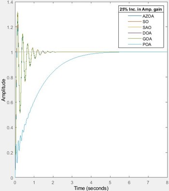

Table 5Characteristics of the AVR system with respect to variation in amplifier’s time constant
Percentage reduction in (%) | Optimization algorithm | (s) | (s) | (s) | % (%) |
25 | SO | 0.0627 | 1.0658 | 0.1403 | 20.1472 |
SAO | 2.4366 | 3.8544 | 6.2083 | 0.0649 | |
AZOA | 0.0662 | 1.0586 | 0.1406 | 15.8427 | |
GOA | 0.0611 | 1.0775 | 0.1366 | 23.0354 | |
DOA | 0.0615 | 1.0749 | 0.1338 | 22.817 | |
POA | 2.4366 | 3.8544 | 6.2083 | 0.0649 | |
50 | SO | 0.0545 | 0.9350 | 0.1159 | 13.7457 |
SAO | 2.4409 | 3.8550 | 6.868 | 0.0891 | |
AZOA | 0.0586 | 0.9246 | 0.1144 | 9.3386 | |
GOA | 0.0532 | 0.9648 | 0.1161 | 16.2471 | |
DOA | 0.0584 | 0.9563 | 0.1161 | 15.7622 | |
POA | 2.4409 | 3.855 | 6.868 | 0.0891 |
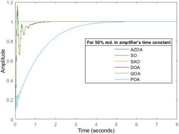
In furtherance to justification of the robustness of the design, the AVR system was also subjected to 25 % and 50 % reductions in the amplifier’s time constant. For the 25 % reduction in amplifier’s time constant, the rise time approximately reduces by 10 % for each of SO, GOA and DOA, reduces by 9 % for AZOA while it increases by 0.15 % for each of SAO and POA. The settling time approximately decreases by 13 % for each of SO and AZOA, decreases by 12 % for each of GOA and DOA while it increases by 0.01 % for each of SAO and POA. The peak time approximately reduces by 4 % for SO, reduces by 10 % for each of SAO and POA, reduces by 12 % for AZOA, reduces by 6 % for GOA and reduces by 8 % for DOA. The percentage overshoot approximately decreases by 20 % for SO, decreases by 27 % for each of SAO and POA, decreases by 24 % for AZOA, decreases by 16 % for GOA and also reduces by 15 % for DOA. For the 50 % reduction in the amplifier’s time constant, the rise time approximately reduces by 22 % for each of SO and GOA, reduces by 19 % for AZOA, reduces by 15 % for DOA, while it increases by 0.3 % for each of SAO and POA. The settling time approximately reduces by 23 % for SO, decreases by 24 % for AZOA, decreases by 17 % for GOA, decreases by 22 % for DOA, while it increases by 0.03 % for each of SAO and POA. The peak time approximately reduces by 20 % for each of SO, GOA and DOA, decreases by 28.7 % for AZOA, while it increases by 0.07 % for each of SAO and POA. The percentage overshoot approximately decreases by 45 % for SO, reduces by 0.2 % for SAO and POA, decreases by 55 % for AZOA and decreases by 41 % for each of GOA and DOA. In both cases of parameter reductions, the SAO and POA-tuned AVR system still exhibit a technically zero overshoot as shown in Fig. 5. The values of the settling times, peak times and rise times averagely indicate the robustness of the design as the system’s transient characteristics were significantly unperturbed by alteration of the amplifier’s time constant. However, the uniqueness of the robustness of the SAO and POA-tuned AVR systems with respect to amplifier’s parameters variation is highly plausible.
Fig. 5The transient response of AVR system for 25 % and 50 % reductions in amplifier’s time constant
Further illustration of the robust performance of the developed AVR system is demonstrated by subjecting it to changes in values of the parameters of the exciter. Table 6 and Table 7 reveal the transient characteristics of the AVR system for an increase in exciter’s gain and exciter’s time constant respectively. As stated earlier, the reason for selecting an increase and not a decrease in parameters relies solely on the operating specifics of the exciter.
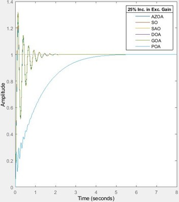
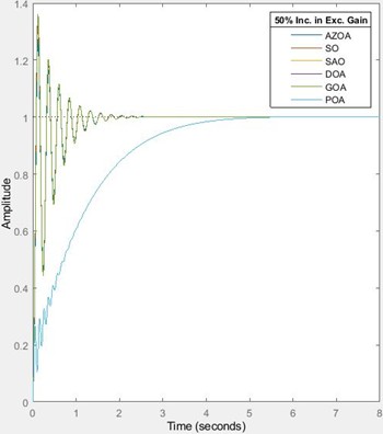
For the 25 % increase in exciter’s gain, the rise time approximately decreases by 13 % for each of SO, AZOA, DOA and GOA, and decreases by 0.03 % for each of SAO and POA. The settling time approximately increases by 10 % for each of SO, AZOA, GOA and DOA while it decreases by 0.1 % for each of SAO and POA. The peak time approximately decreases by 10 % for each of SO, GOA and DOA, decreases by 7 % for each of SAO and POA and also decreases by 18 % for AZOA. The percentage overshoot approximately increases by 17 % for each of SO, AZOA, GOA and DOA while it decreases by 12 % for each of SAO and POA. For the 50 % increase in exciter’s gain, the rise time approximately decreases by 22 % for each of SO and AZOA, decreases by 0.04 % for each of SAO and POA, and decreases by 23 % for each of GOA and DOA. The settling time approximately increases by 21 % for each of SO, AZOA, GOA and DOA while it decreases by 0.2 % for each of SAO and POA. The peak time approximately decreases by 18 % for each of SO and GOA, decreases by 11 % for each of SAO and POA, decreases by 25 % for AZOA and also decreases by 17 % for DOA. The percentage overshoot approximately increases by 31 % for SO, increases by 32 % for each of AZOA, GOA and DOA, it decreases by 34 % for each of SAO and POA. These percentage variations imply that the presented design offers low sensitivity to variation of exciter’s gain. It is remarkable to observe the unique performances of the SAO and the POA in ensuring zero overshoot even in the presence of variation of exciter’s gain; the calculated percentage change in percentage overshoot does not nullify the technical reality that the percentage overshoot remains zero (approximately zero). Hence, the safety of the power equipment cannot be jeopardized by alteration of the exciter’s gain and more importantly, when the SAO and POA are deployed. Though it is expected, the near sameness of convergence of the AZOA, SO, GOA and DOA in this AVR system design is intuitively appreciable with their unique settling times which imply minimal control efforts. However, the robustness of the SAO and POA-tuned AVR system shows their superior performance in terms of zero overshoot over the ones obtained by using the other algorithms. Conclusively, although much control effort is required for the SAO and the POA-tuned AVR system, the settling time is unperturbed at variation of exciter’s gain.
Table 6Characteristics of the AVR system with respect to variation in exciter’s gain
Percentage increase in (%) | Optimization algorithm | (s) | (s) | (s) | % (%) |
25 | SO | 0.0603 | 1.3457 | 0.1307 | 29.3665 |
SAO | 2.4323 | 3.8486 | 6.4087 | 0.0798 | |
AZOA | 0.0630 | 1.3420 | 0.1309 | 24.2818 | |
GOA | 0.0590 | 1.3506 | 0.1309 | 32.0655 | |
DOA | 0.0592 | 1.3494 | 0.1308 | 31.5440 | |
POA | 2.4323 | 3.8486 | 6.4087 | 0.0798 | |
50 | SO | 0.0538 | 1.4726 | 0.1197 | 32.9685 |
SAO | 2.4321 | 3.8452 | 6.1208 | 0.0586 | |
AZOA | 0.0563 | 1.4688 | 0.1198 | 27.3568 | |
GOA | 0.0526 | 1.4771 | 0.1199 | 36.0243 | |
DOA | 0.0528 | 1.4760 | 0.1199 | 35.4339 | |
POA | 2.4321 | 3.8452 | 6.1208 | 0.0586 |
Fig. 6Response of the AVR system for increase in exciter’s gain
Interestingly, the transient responses of the proposed AVR design when subjected to variations of amplifier’s gain and exciter gain are similar. The sameness is revealed in the depicted figures and tables of each of the transient responses. Table 7 and Fig. 7 are the results of the transient response of the proposed system on subjection to variation in the exciter’s time constant.
Table 7Characteristics of the AVR system with respect to variation in exciter’s time constant
Percentage increase in (%) | Optimization algorithm | (s) | (s) | (s) | % (%) |
25 | SO | 0.0788 | 1.0704 | 0.1735 | 24.2430 |
SAO | 2.4286 | 3.8511 | 6.0981 | 0.0554 | |
AZOA | 0.0815 | 1.0712 | 0.1700 | 20.4559 | |
GOA | 0.0778 | 1.0752 | 0.1738 | 26.0121 | |
DOA | 0.0781 | 1.0740 | 0.1702 | 25.7433 | |
POA | 2.4286 | 3.8511 | 6.0981 | 0.0544 | |
50 | SO | 0.0870 | 1.1582 | 0.1887 | 23.3786 |
SAO | 2.4246 | 3.8483 | 6.8235 | 0.0907 | |
AZOA | 0.0898 | 1.1600 | 0.1986 | 19.8627 | |
GOA | 0.0858 | 1.1629 | 0.1910 | 24.8496 | |
DOA | 0.0863 | 1.1617 | 0.1871 | 24.5799 | |
POA | 2.4246 | 3.8483 | 6.8235 | 0.0907 |
Fig. 7Transient response of the AVR system for increase in exciter’s time constant

In Table 7 and Fig. 7, the pictorial illustrations of the transient response of the AVR system when subjected to a 25 % and 50 % increase in exciter’s time constant are shown. For a 25 % increase in exciter’s time constant, the rise time approximately increases by 13.5 % for SO, increases by 13 % for AZOA, increases by 14 % for each of GOA and DOA, while it decreases by 0.2 % for each of SAO and POA. The settling time approximately reduces by 12 % for each of SO, AZOA, GOA and DOA, and also reduces by 0.1 % for each of SAO and POA. The peak time approximately increases by 19 % for each of SO and GOA, increases by 6 % for AZOA, increases by 17 % for DOA, it reduces by 11 % for each of SAO and POA. The percentage overshoot approximately reduces by 3 % for SO, reduces by 38 % for each of SAO and POA, reduces by 1 % for AZOA, reduces by 9 % for GOA and reduces by 4 % for DOA. For a 50 % increase in exciter’s time constant, the rise time approximately rises by 25 % for SO, rises by 24 % for AZOA, rises by 25 % for GOA, rises by 3 % for DOA, while it reduces by 0.3 % for each of SAO and POA. The settling time approximately reduces by 5 % for each of SO, AZOA, GOA and DOA, and reduces by 0.1 % for each of SOA and POA. The peak time approximately increases by 30 % for SO, rises by 23 % for AZOA, rises by 31 % for GOA, rises by 29 % for DOA, while it reduces by 1 % for each of SAO and POA. The percentage maximum overshoot approximately rises by 7 % for SO, reduces by 4 % for AZOA, and reduces by 9 % for each of GOA and DOA while it increases by 2 % for each of SAO and POA. The robustness of the SAO and POA-tuned AVR systems in terms of variation in the exciter’s time constant is superb. Hence, the safety of the power equipment is guaranteed even in the presence of alteration in the exciter’s time constant. Furthermore, the robustness of the proposed AVR design with respect to variation in the values of the generator’s parameters is investigated as depicted in Table 8, Table 9, Fig. 8 and Fig. 9.
Table 8Transient characteristics for a reduction in generator’s gain
Percentage reduction in (%) | Optimization algorithm | (s) | (s) | (s) | % (%) |
15 | SO | 0.0793 | 1.0262 | 0.1666 | 17.3042 |
SAO | 2.8216 | 4.5158 | 7.1947 | 0 | |
AZOA | 0.0830 | 1.0230 | 0.1659 | 13.0579 | |
GOA | 0.0770 | 1.2639 | 0.1643 | 19.6883 | |
DOA | 0.0777 | 1.2574 | 0.1610 | 19.3099 | |
POA | 2.8216 | 4.5158 | 7.1947 | 0 | |
30 | SO | 0.0934 | 1.1132 | 0.1795 | 7.9570 |
SAO | 3.3823 | 5.4912 | 9.5622 | 0 | |
AZOA | 0.0990 | 1.1062 | 0.1799 | 3.5413 | |
GOA | 0.0914 | 1.1324 | 0.1765 | 10.4297 | |
DOA | 0.0919 | 1.1275 | 0.1731 | 9.9771 | |
POA | 3.3823 | 5.4912 | 9.5622 | 0 |
Fig. 8Response for a reduction in generator’s gain
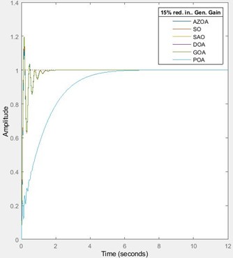
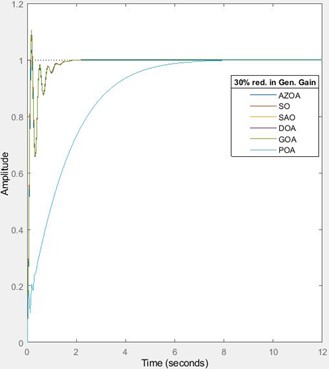
In Fig. 8 and Table 8, the transient behaviours of the AVR design when subjected to 15 % and 30 % reduction in the generator’s gain are presented. For the 15 % reduction in the generator’s gain, the rise time approximately increases by 14 % for each of SO and DOA, increases by 16 % for each of SAO and POA, increases by 15 % for AZOA and increases by 13 % for GOA. The settling time approximately reduces by 16 % for each of SO, AZOA, increases by 17 % for each of SOA and POA, increases by 3 % for each of GOA and DOA. The peak time approximately increases by 14 % for SO, increases by 5 % for each of SAO and POA, increases by 3 % for AZOA, increases by 13 % for GOA and increases by 11 % for DOA. The percentage overshoot approximately reduces by 31 % for SO, reduces by 100 % for each of SAO and POA, reduces by 37 % for AZOA and reduces by 28 % for each of GOA and GOA. For a 30 % reduction in the generator’s gain, the rise time approximately increases by 35 % for each of SO and DOA, rises by 39 % for each of SAO and POA, increases by 37 % for AZOA and rises by 34 % for GOA. The settling time approximately decreases by 9 % for each of SO and AZOA, reduces by 8 % for each of GOA and DOA, while it increases by 42 % for each of SAO and POA. The peak time approximately increases by 23 % for SO, increases by 39 % for each of SAO and POA, increases by 12 % for AZOA, increases by 21 % for GOA and increases by 19 % for DOA. The percentage overshoot approximately reduces by 68 % for SO, reduces by 100 % for each of SAO and POA, reduces by 83 % for AZOA, reduces by 62 % for GOA and reduces by 63 % for DOA. The values of the percentage change in each of the transient characteristics indicate that the AVR design is a little sensitive to changes in the generator’s gain. However, the overshoot remains zero for the POA and SAO-tuned AVR system. Hence, the robustness of the design to changes in the generator’s gain is not guaranteed; albeit, the plausibility of the POA and SAO-based system for overshoot elimination is remarkable. The behaviours of the system when subjected to 25 % and 50 % rise in the generator’s time constant are discussed.
Table 9Transient response for the AVR system for increase in the generator’s time-constant
Percentage increase in (%) | Optimization algorithm | (s) | (s) | (s) | % (%) |
25 | SO | 0.0820 | 1.0156 | 0.1568 | 15.2130 |
SAO | 2.4005 | 3.3649 | 5.1540 | 1.2630 | |
AZOA | 0.0870 | 1.0073 | 0.1575 | 10.6975 | |
GOA | 0.0800 | 1.0261 | 0.1547 | 17.2932 | |
DOA | 0.0803 | 1.0238 | 0.1551 | 16.8539 | |
POA | 2.4005 | 3.3649 | 5.1540 | 1.2630 | |
50 | SO | 0.0959 | 0.7898 | 0.1698 | 7.608 |
SAO | 2.4163 | 6.3386 | 4.8997 | 3.0881 | |
AZOA | 0.1029 | 0.7833 | 0.1701 | 2.9944 | |
GOA | 0.0930 | 0.8002 | 0.1681 | 9.8005 | |
DOA | 0.0935 | 0.7977 | 0.1684 | 9.3845 | |
POA | 2.4163 | 6.3386 | 4.8997 | 3.0881 |
Fig. 9Response of the AVR system for increase in generator time constant


For a 25 % increase in the generator’s constant, the rise time approximately increases by 18 % for each of SO, GOA and DOA, rises by 20 % for AZOA, while it reduces by 1 % for SAO and POA. The settling time approximately reduces by 17 % for each of the SO, AZOA, reduces by 13 % for each of the SAO and POA, and also reduces by 16 % for each of the GOA and DOA. The peak time approximately increases by 8 % for SO, increases by 6 % for GOA, rises by 7 % for DOA, while it reduces by 2 % for AZOA and reduces by 25 % for each of the SAO and POA. The percentage overshoot approximately reduces by 39 % for SO, reduces by 48 % for AZOA, reduces by 37 % for each of GOA and DOA, while it increases by 1314 % for each of SAO and POA. On subjecting the system to 50 % increase in the generator’s time constant, the rise time approximately rises by 39 % for SO, rises by 67 % for AZOA, increases by 37 % for each of GOA and DOA, while it reduces by 1 % for each of the SAO and POA. The settling time approximately reduces by 35 % for each of the SO, GOA and DOA, reduces by 36 % for AZOA, while it rises by 65 % for each of SAO and POA. The peak time approximately increases by 17 % for SO, rises by 6 % for AZOA, rises by 15 % for GOA, rises by 16 % for DOA, while it decreases by 29 % for each of SAO and POA. The percentage overshoot approximately reduces by 70 % for SO, reduces by 86 % for AZOA, reduces by 64 % for GOA, reduces by 65 % for DOA, while it increases by 3358 % for each of the SAO and POA. The system loses its robustness when subjected to 25 % and 50 % increase in the generator’s time constant. Hence, the sensitivity of the system increases with changes in the generator’s parameter. However, in achieving a minimized overshoot, the performances of the SAO and POA-tuned AVR systems cannot be relegated. In furtherance to test the robustness, the developed AVR system is subjected to changes in the sensor’s parameters and the results are illustrated in Table 10, Table 11, Fig. 10 and Fig. 11.
Table 10Response of the AVR system for reductions in sensor gain
Percentage reduction in (%) | Optimization algorithm | (s) | (s) | (s) | % (%) |
25 | SO | 0.0876 | 1.0798 | 0.1746 | 11.2716 |
SAO | 3.1714 | 5.1192 | 9.3519 | 0 | |
AZOA | 0.0923 | 1.0738 | 0.1746 | 6.9050 | |
GOA | 0.0860 | 1.0940 | 0.1718 | 13.7099 | |
DOA | 0.0865 | 1.0909 | 0.1685 | 13.2691 | |
POA | 3.1714 | 5.1192 | 9.3519 | 0 | |
50 | SO | 0.1407 | 1.4549 | 2.9627 | 0.0526 |
SAO | 4.6443 | 7.7694 | 13.4856 | 0 | |
AZOA | 0.7597 | 1.4646 | 3.7446 | 0.0175 | |
GOA | 0.1308 | 1.4989 | 2.9384 | 0.0655 | |
DOA | 0.1320 | 1.4876 | 2.9432 | 0.0679 | |
POA | 4.6443 | 7.7694 | 13.4856 | 0 |
Fig. 10Transient response of the AVR system for reductions in sensor’s gain
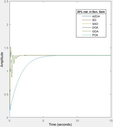
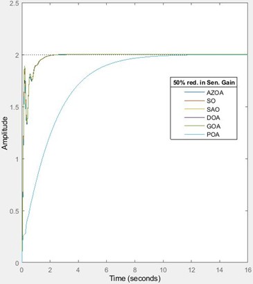
Table 10 and Fig. 10 show the transient characteristics of the system when subjected to 25 % and 50 % reductions in sensor gain. On subjecting the developed AVR system to 25 % reduction in sensor gain, the rise time approximately increases by 26 % for each of the SO, GOA, rises by 39 % for each of SAO and POA, rises by 27 % for each of AZOA and DOA. The settling time approximately decreases by 11 % for each of the SO, DOA and GOA, reduces by 12 % for AZOA, while it rises by 33 % for each of the SAO and POA. The peak time approximately increases by 20 % for SO, increases by 36 % for each of the SAO and POA, increases by 9 % for AZOA, rises by 18 % for GOA and rises by 16 % for the DOA. The percentage overshoot approximately reduces by 55 % for SO, reduces by 100 % for each of the SAO and POA, reduces by 67 % for AZOA, reduces by 50 % for GOA and reduces by 51 % for the DOA. These percentage variations indicate the sensitivity of the developed AVR design to a 25 % reduction in sensor gain; however, it is still remarkable that the overshoot is eliminated for the case of the SAO and the POA-tuned AVR system. For the 50 % reduction in sensor gain, the rise time approximately rises by 103 % for the SO, rises by 91 % for each of the SAO and POA, rises by 949 % for the AZOA, rises by 92 % for the GOA and rises by 93 % for the DOA. The settling time approximately increases by 19 % for the SO, increases by 102 % for each of the SAO and POA, increases by 20 % for the AZOA, and increases by 22 % for each of the GOA and DOA. The peak time approximately increases by 1935 % for the SO, increases by 97 % for each of the SAO and POA, increases by 2233 % for the AZOA, rises by 1915 % for the GOA and rises by 1930 % for the DOA. The percentage overshoot approximately reduces by 100 % for each of the SO, SAO, POA, AZOA, GOA and DOA. Hence for a 50 % reduction in the sensor’s gain, there is a total elimination of the percentage overshoot in all cases of deployment of algorithms on the AVR design. However, the system shows perturbation in the presence of variation of the sensor’s gain. Conclusively, the safety of the equipment is still guaranteed in the case of the SAO and POA-tuned AVR systems. Table 11 and Fig. 11 show the behaviour of the transient response of the system when subjected to 25 % and 50 % increase in the sensor’s time constant.
Table 11Response of the AVR system for increase in sensor time constant
Percentage increase in (%) | Optimization algorithm | (s) | (s) | (s) | % (%) |
25 | SO | 0.0684 | 1.2416 | 0.1470 | 28.1941 |
SAO | 2.4278 | 3.8446 | 6.6242 | 0.0891 | |
AZOA | 0.0714 | 1.2413 | 0.1473 | 23.5167 | |
GOA | 0.0671 | 1.2459 | 0.1472 | 30.5787 | |
DOA | 0.0673 | 1.2448 | 0.1472 | 30.1178 | |
POA | 2.4278 | 3.8446 | 6.6242 | 0.0891 | |
50 | SO | 0.0676 | 1.5188 | 0.1487 | 31.2819 |
SAO | 2.4226 | 3.8353 | 6.7262 | 0.0926 | |
AZOA | 0.0706 | 1.5058 | 0.1489 | 26.3840 | |
GOA | 0.0662 | 1.5236 | 0.1489 | 33.7800 | |
DOA | 0.0664 | 1.5223 | 0.1488 | 33.2971 | |
POA | 2.4226 | 3.8353 | 6.7262 | 0.0926 |
Fig. 11Transient response of the proposed AVR system for increase in sensor’s time constant
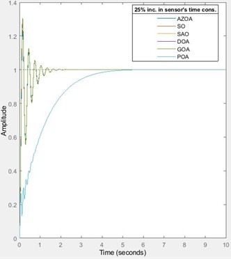
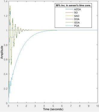
For the 25 % increase in the sensor’s time constant, the rise time of the AVR system approximately decreases by `1 % for each of the SO and AZOA, reduces by 0.2 % for each of SAO and POA, reduces by 1.5 % for each of the GOA and DOA. The settling approximately increases by 2 % for each of the SO, AZOA, GOA and DOA, while it reduces by 0.2 % for each of the SAO and POA. The peak time approximately increases by 1 % for each of the SO and GOA, reduces by 8 % for AZOA, rises by 1.5 % for the DOA, and reduces by 3.5 % for each of the SAO and POA. The percentage overshoot approximately rises by 12 % for each of the SO, GOA and DOA, rises by 13 % for the AZOA, while it reduces by 0.2 % for each of the SAO and POA. These percentage variations indicate the low sensitivity of the developed AVR system to a 25 % increase in the sensor’s time constant. On subjecting the system to a 50 % increase in the sensor’s time constant, the rise time approximately decreases by 3 % for each of the SO, GOA and DOA, reduces by 0.4 % for each of the SAO and POA, and reduces by 2.5 % for the AZOA. The settling time approximately rises by 25 % for the SO, rises by 24 % for each of the AZOA, GOA and DOA, while it reduces by 0.5 % for each of the SAO and POA. The peak time approximately increases by 2 % for each of the SO and GOA, rises by 3 % for the DOA, reduces by 2 % for each of the SAO and POA, and reduces by 7 % for the AZOA. The percentage overshoot approximately increases by 25 % for the SO, rises by 4 % for each of the SAO and POA, rises by 27 % for the AZOA, and rises by 24 % for each of the GOA and DOA. It is interestingly notable that the AVR exhibits a good level of insensitivity to a 50 % increase in the sensor’s time constant. Hence, the developed design is robust to variation in the sensor’s time constant.
5. Conclusions
In this paper, a PID-based AVR system with a tunable stabilizing loop is presented. Six state-of-the-art algorithms were deployed to obtain optimal values of the PID gains and the gain of the inner stabilizing loop. Apart from ensuring the stability of the AVR system, the POA and SAO tuned-AVR systems exhibit superior performance in ascertaining zero overshoots even in the presence of parameter variations. It is pertinent to also state that the SO, AZOA, GOA and DOA-tuned AVR systems require minimal control efforts to achieve perfect tracking of the generator’s terminal voltage when compared to those of the other two algorithms; however, they have some overshoots. Also, the system exhibits robustness when subjected to changes in the parameters of the amplifier, exciter and sensor; however, the alteration in the sensor’s gain and the generator’s parameters tends to make the system lose robustness. Emphatically, the developed AVR system is suitable for the realization of zero percentage overshoot. Hence, the safety of power and instrumentation equipment is guaranteed when the SAO and POA-tuned AVR systems are deployed on PID controller-based AVR systems with an adjustable gain in the stabilizing loop in power generating stations.
References
-
E. Çelik and R. Durgut, “Performance enhancement of automatic voltage regulator by modified cost function and symbiotic organisms search algorithm,” Engineering Science and Technology, an International Journal, Vol. 21, No. 5, pp. 1104–1111, Oct. 2018, https://doi.org/10.1016/j.jestch.2018.08.006
-
M. A. Sahib, “A novel optimal PID plus second order derivative controller for AVR system,” Engineering Science and Technology, an International Journal, Vol. 18, No. 2, pp. 194–206, Jun. 2015, https://doi.org/10.1016/j.jestch.2014.11.006
-
M. S. Alamgir and S. Dev, “Design and implementation of an automatic voltage regulator with a great precision and proper hysteresis,” International Journal of Advanced Science and Technology, Vol. 75, pp. 21–32, Feb. 2015, https://doi.org/10.14257/ijast.2015.75.03
-
D. Izci, R. M. Rizk-Allah, V. Snášel, S. Ekinci, F. A. Hashim, and L. Abualigah, “A novel control scheme for automatic voltage regulator using novel modified artificial rabbits optimizer,” e-Prime – Advances in Electrical Engineering, Electronics and Energy, Vol. 6, p. 100325, Dec. 2023, https://doi.org/10.1016/j.prime.2023.100325
-
P. Mangera, F. H. Sumbung, and D. Parenden, “Automatic voltage regulator (AVR) controller design based on Routh’s crution stability analysis in diesel-based power plants,” in Proceedings of the International Conference on Science and Technology (ICST 2018), Vol. 1, pp. 545–553, Jan. 2018, https://doi.org/10.2991/icst-18.2018.113
-
J. Faiz, G. Shahgholian, and M. Arezoomand, “Analysis and simulation of the AVR system and parameters variation effects,” in 2007 International Conference on Power Engineering, Energy and Electrical Drives, pp. 450–453, Apr. 2007, https://doi.org/10.1109/powereng.2007.4380101
-
B. Ozgenc, M. S. Ayas, and I. H. Altas, “Performance improvement of an AVR system by symbiotic organism search algorithm-based PID-F controller,” Neural Computing and Applications, Vol. 34, No. 10, pp. 7899–7908, Jan. 2022, https://doi.org/10.1007/s00521-022-06892-4
-
F. A. G. S. Babu and S. B. T. Chiranjeevi, “Implementation of fractional order PID controller for an AVR system using GA and ACO optimization techniques,” IFAC-PapersOnLine, Vol. 49, No. 1, pp. 456–461, Jan. 2016, https://doi.org/10.1016/j.ifacol.2016.03.096
-
M. Z. M. Tumari, M. A. Ahmad, M. R. Ghazali, and M. H. Suid, “Optimizing PID controller parameters for robust automatic voltage regulator system through indirect design approach-2,” Global Energy Interconnection, Vol. 7, No. 5, pp. 682–696, Oct. 2024, https://doi.org/10.1016/j.gloei.2024.10.009
-
H. Gozde, “Robust 2DOF state-feedback PI-controller based on meta-heuristic optimization for automatic voltage regulation system,” ISA Transactions, Vol. 98, pp. 26–36, Mar. 2020, https://doi.org/10.1016/j.isatra.2019.08.056
-
M. Modabbernia, B. Alizadeh, A. Sahab, and M. M. Moghaddam, “Robust control of automatic voltage regulator (AVR) with real structured parametric uncertainties based on H∞ and μ-analysis,” ISA Transactions, Elsevier BV, 2020.
-
A. Mandali, L. Dong, and A. Morinec, “Robust controller design for automatic voltage regulation,” in American Control Conference (ACC), pp. 2617–2622, Jul. 2020, https://doi.org/10.23919/acc45564.2020.9147208
-
M. Elsisi, M.-Q. Tran, H. M. Hasanien, R. A. Turky, F. Albalawi, and S. S. M. Ghoneim, “Robust model predictive control paradigm for automatic voltage regulators against uncertainty based on optimization algorithms,” Mathematics, Vol. 9, No. 22, p. 2885, Nov. 2021, https://doi.org/10.3390/math9222885
-
M. Ahmadnia, A. Hajipour, and H. Tavakoli, “Robust variable-order fractional PID-LP fuzzy controller for Automatic Voltage Regulator systems,” Applied Soft Computing, Vol. 167, p. 112268, Dec. 2024, https://doi.org/10.1016/j.asoc.2024.112268
-
T. Dogruer and M. S. Can, “Design and robustness analysis of fuzzy PID controller for automatic voltage regulator system using genetic algorithm,” Transactions of the Institute of Measurement and Control, Vol. 44, No. 9, pp. 1862–1873, Jan. 2022, https://doi.org/10.1177/01423312211066758
-
M. J. Lawal, S. U. Hussein, B. Saka, S. U. Abubakar, and I. S. Attah, “Intelligent fuzzy-based automatic voltage regulator with hybrid optimization learning method,” Scientific African, Vol. 19, p. e01573, Mar. 2023, https://doi.org/10.1016/j.sciaf.2023.e01573
-
D. N. C. Cuesta and F. Martínez Santa, “Optimization of an automatic voltage regulator AVR on a synchronous machine using fuzzy control,” in Journal of Physics: Conference Series, Vol. 2135, No. 1, p. 012004, Dec. 2021, https://doi.org/10.1088/1742-6596/2135/1/012004
-
V. Kumar and V. Sharma, “Automatic voltage regulator with particle swarm optimized model predictive control strategy,” in 1st IEEE International Conference on Measurement, Instrumentation, Control and Automation (ICMICA), pp. 1–5, Jun. 2020, https://doi.org/10.1109/icmica48462.2020.9242783
-
S. Alghamdi, A. B. Wazir, H. H. H. Awaji, A. A. Alhussainy, H. F. Sindi, and M. Rawa, “Tuning PID controller parameters of automatic voltage regulator (AVR) Using particle swarm optimization: a comparative study,” in IEEE PES Conference on Innovative Smart Grid Technologies – Middle East (ISGT Middle East), pp. 1–6, Mar. 2023, https://doi.org/10.1109/isgtmiddleeast56437.2023.10078497
-
Y. O. M. Sekyere, P. O. Ajiboye, F. B. Effah, and B. T. Opoku, “Optimizing PID control for automatic voltage regulators using ADIWACO PSO,” Scientific African, Vol. 27, p. e02562, Mar. 2025, https://doi.org/10.1016/j.sciaf.2025.e02562
-
E. Kose, “Optimal control of AVR system with tree seed algorithm-based PID controller,” IEEE Access, Vol. 8, pp. 89457–89467, Jan. 2020, https://doi.org/10.1109/access.2020.2993628
-
B. Hekimoglu and S. Ekinci, “Grasshopper optimization algorithm for automatic voltage regulator system,” in 5th International Conference on Electrical and Electronic Engineering (ICEEE), pp. 152–156, May 2018, https://doi.org/10.1109/iceee2.2018.8391320
-
A. Sikander, P. Thakur, R. C. Bansal, and S. Rajasekar, “A novel technique to design cuckoo search based FOPID controller for AVR in power systems,” Computers and Electrical Engineering, Vol. 70, pp. 261–274, Aug. 2018, https://doi.org/10.1016/j.compeleceng.2017.07.005
-
T. Spoljaric, C. Lusetic, and V. Simovic, “Optimization of PID controller in AVR system by using ant lion optimizer algorithm,” in 41st International Convention on Information and Communication Technology, Electronics and Microelectronics (MIPRO), pp. 1522–1526, May 2018, https://doi.org/10.23919/mipro.2018.8400274
-
F. A. Hashim and A. G. Hussien, “Snake Optimizer: A novel meta-heuristic optimization algorithm,” Knowledge-Based Systems, Vol. 242, p. 108320, Apr. 2022, https://doi.org/10.1016/j.knosys.2022.108320
-
J. O. Agushaka, A. E. Ezugwu, and L. Abualigah, “Gazelle optimization algorithm: a novel nature-inspired metaheuristic optimizer,” Neural Computing and Applications, Vol. 35, No. 5, pp. 4099–4131, Oct. 2022, https://doi.org/10.1007/s00521-022-07854-6
-
A. T. Salawudeen, M. B. Mu’Azu, Y. A. Sha’Aban, and A. E. Adedokun, “A novel smell agent optimization (SAO): an extensive CEC study and engineering application,” Knowledge-Based Systems, Vol. 232, p. 107486, Nov. 2021, https://doi.org/10.1016/j.knosys.2021.107486
-
Y. Batmani and H. Golpîra, “Automatic voltage regulator design using a modified adaptive optimal approach,” International Journal of Electrical Power and Energy Systems, Vol. 104, pp. 349–357, Jan. 2019, https://doi.org/10.1016/j.ijepes.2018.07.001
-
Yu Zaw and Wint Yu, “Performance analysis of automatic voltage regulator in power generation system,” International Journal of Science and Engineering Applications, Vol. 8, No. 7, pp. 180–185, Jul. 2019, https://doi.org/10.7753/ijsea0807.1003
-
R. Mok and M. A. Ahmad, “Fast and optimal tuning of fractional order PID controller for AVR system based on memorizable-smoothed functional algorithm,” Engineering Science and Technology, an International Journal, Vol. 35, p. 101264, Nov. 2022, https://doi.org/10.1016/j.jestch.2022.101264
-
A. T. Sulaiman et al., “A particle swarm and smell agent-based hybrid algorithm for enhanced optimization,” Algorithms, Vol. 17, No. 2, p. 53, Jan. 2024, https://doi.org/10.3390/a17020053
-
P. Trojovský and M. Dehghani, “Pelican optimization algorithm: a novel nature-inspired algorithm for engineering applications,” Sensors, Vol. 22, No. 3, p. 855, Jan. 2022, https://doi.org/10.3390/s22030855
-
S. Zhao, T. Zhang, S. Ma, and M. Chen, “Dandelion optimizer: a nature-inspired metaheuristic algorithm for engineering applications,” Engineering Applications of Artificial Intelligence, Vol. 114, No. 2, p. 105075, Sep. 2022, https://doi.org/10.1016/j.engappai.2022.105075
-
S. Mohapatra and P. Mohapatra, “American zebra optimization algorithm for global optimization problems,” Scientific Reports, Vol. 13, No. 1, pp. 1–51, Mar. 2023, https://doi.org/10.1038/s41598-023-31876-2
About this article

The authors have not disclosed any funding.
The datasets generated during and/or analyzed during the current study are available from the corresponding author on reasonable request.
Johnson Obari: conceptualization, methodology, resources, administration, software, writing-original draft preparation. Umar Abubakar: formal analysis, methodology, supervision, validation, writing-review and editing. Ramat Yususf: data curation, methodology, writing-original draft preparation, curation, resources, visualization. Momoh Muyideen: resources, software, formal analysis, investigation, validation, writing-review and editing.
The authors declare that they have no conflict of interest.
