Abstract
With rapid urbanization, conflicts between underground pipeline construction and existing bridge infrastructure have become increasingly prominent. This research aims to fill the gap in understanding the differential impact mechanisms and dynamic coupling effects between construction activities and bridge foundation stability. The study employs the finite element model to simulate the construction process, including working well excavation and pipe jacking, in a 120×80×30-meter three-dimensional model. Results show that both excavation and pipe jacking activities have minimal impact on the adjacent bridge foundations, with maximum horizontal displacements remaining within safe limits. This research provides a methodological framework for urban infrastructure risk assessment, offering technical references for balancing underground construction activities with existing structural protection.

Highlights
- Conflicts between underground pipeline construction and existing bridge infrastructure have become increasingly prominent
- Provide a methodological framework for urban infrastructure risk assessment
- Offer technical references for balancing underground construction activities with existing structural protection
1. Introduction
With the rapid urbanization, the conflict between underground pipeline construction and existing bridge infrastructure has become increasingly prominent. During sewage pipeline construction, soil disturbance, mechanical vibration, and groundwater environment changes may cause irreversible structural damage to adjacent bridge foundations [1, 2].
Current research predominantly focuses on soil mechanical responses during pipeline construction, such as safety distance calculations. Cao et al. [3] investigated the impact of drainage flow velocity on the erosion of cohesive soil and the evolution of ground collapse, concluding that increased flow velocity significantly exacerbates soil erosion and the process of ground collapse. Ren et al. [4] explored the influence of fines content on internal erosion around sand-fines mixtures and ground collapse, finding that higher fines content leads to more severe internal erosion and a greater likelihood of ground collapse. Dai et al. [5] used experimental and numerical methods to study the mechanism of ground collapse induced by underground drainage pipe leakage, identifying that the head difference and leakage volume at the leakage point are key factors influencing collapse. Li et al. [6] proposed a non-Darcy flow CFD-DEM method to simulate ground collapse caused by leakage through underground pipeline defects, revealing the complexity of the interaction between seepage flow and surrounding soil. Indiketiya et al. [7] assessed internal erosion and ground deformation caused by defective sewer pipes through laboratory model tests, showing that pipe leakage can lead to significant ground settlement and localized deformation. Additionally, Tan et al. [8] analyzed subsurface cavities and ground collapse due to broken pipe leakage using model tests, indicating that the location and leakage volume of the pipe rupture significantly affect the morphology and scale of collapse. These studies collectively demonstrate that leakage, defects, or construction vibrations during sewage pipeline construction can significantly impact the stability of surrounding soil and existing structures (such as bridge foundations), emphasizing the importance of effective risk management and monitoring during construction.
However, systematic studies on the differential impact mechanisms of various construction techniques and dynamic coupling effects between groundwater fluctuations and negative skin friction of piles remain inadequate. Furthermore, existing codes lack clarity on disturbance thresholds in soft soil areas, leading to arbitrary selection of preventive measures in engineering practices. Therefore, it is critical to develop refined impact assessment models integrating multidisciplinary theories and field monitoring data to guide scientific decision-making in construction projects.
This study aims to establish a finite element model (FEM) to systematically evaluate the impacts of sewage pipeline construction on adjacent bridge pile foundations. The novelty of this study lies in the development of a multi-physics coupling FEM model that integrates transient construction dynamics with long-term geomechanical responses. Unlike conventional static analysis, our approach incorporates real-time construction parameter variations, enabling the simulation of complex soil-structure interaction mechanisms during progressive construction phases. This work will advance the understanding of underground construction risks and help to refine safety standards for urban infrastructure projects.
2. Project overview
This project is a critical sub-component of a municipal pipeline renovation initiative. The project aims to enhance the regional sewage interception network and improve water body ecological management capabilities. During construction, it is essential to evaluate the structural impacts on adjacent bridge foundation.
The interaction between sewage pipelines and bridges is characterized by spatial proximity and mechanical effects. The longitudinal axis of the pipeline intersects with the bridge's pile foundation in a planar manner. With a design burial depth of 5-8 meters for the pipeline bottom, it falls within the lateral influence zone of the bridge's pile foundation. During construction, the additional stress generated by pipe jacking operations may alter the bearing state of the pile foundation. Dewatering activities can affect the effective stress distribution in the surrounding soil, while vibration loads may trigger liquefaction risks in the fine sand layer. Consequently, the project mandates strict control of surface settlement to no more than 10 mm, and differential settlement between adjacent structures must be kept below 1/1000.
The geological survey reveals that the strata in the construction area, from top to bottom, consist of a 1.5-3-meter-thick layer of artificial fill soil, a 4-6-meter-thick layer of highly compressible silty soil, a 2.5-4.5-meter-thick layer of medium-dense fine sand, and a 3-5-meter-thick layer of strongly weathered rock. The silty soil exhibits high sensitivity, making it susceptible to thixotropic effects due to construction disturbances. The fine sand has strong permeability and poses a moderate liquefaction risk. The shallow groundwater table (1.2-2 meters deep) further exacerbates the risk of piping. These unique geological conditions present significant challenges for maintaining stability during pipe jacking operations.
3. Establishment of numerical model
The modeling analysis employs the MIDAS GTS NX three-dimensional finite element platform to construct a 120×80×30-meter three-dimensional solid model, as shown in Fig. 1. The soil is simulated using the modified Mohr-Coulomb constitutive model to capture its elastic-plastic behavior, while the structural elements are modeled as linearly elastic. The normal spring stiffness at the pile-soil interface is set to 3×10⁴ kN/m3. The construction process is simulated in stages, including ground stress equilibrium, staged pipe jacking, pipe segment installation, synchronous grouting, and pump house load application. Sensitivity analyses are performed for key parameters such as grouting pressure (0.2-0.5 MPa), pipe jacking speed (20-50 mm/min), and groundwater level variations (±1 m).
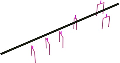
Fig. 2 illustrates the finite element model of the working shaft and bridge pile foundation, along with their spatial relationship. Fig. 3 shows the finite element model of the working shaft, while Fig. 4 displays the finite element model of the sewer pipeline structure and its spatial relationship with the bridge foundation. The pipeline structure and working shaft are simulated using shell elements. The bridge pile foundation and pier column structures are modeled with beam elements.
Fig. 1Finite element model
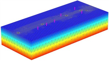
Fig. 2Working shaft and bridge pile foundation model along with their spatial relationship
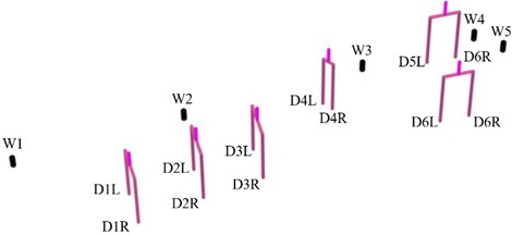
Fig. 3Finite element model of the working shaft (intermediate shaft)
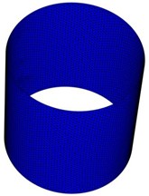
Fig. 4Sewer pipeline structure and its spatial relationship with the bridge foundation
The boundary conditions of the model are defined as follows: the bottom boundary is fully constrained in both horizontal and vertical directions; the side boundaries are fixed horizontally but free vertically; and the top surface of the bridge pier columns is constrained against vertical displacement. During the construction of the working well (intermediate and receiving wells) and pipe jacking, it is assumed that the groundwater level remains constant. Considering the most unfavorable conditions, the stable groundwater level is set at a burial depth of 2.80 meters, and undrained analysis is applied for both the working well and pipe jacking construction.
The finite element model first simulates the initial stress field, assuming that the bridge pile foundation has already been completed. It then sequentially simulates the excavation of the working well (both intermediate and receiving wells), followed by the pipe jacking construction process.
During pipe jacking, the advance length is excavated first using mud-level balance techniques, followed by the forward thrusting of pipe sections. These two procedures are repeated to achieve continuous pipe installation. In this numerical model, the entire process of pipe advancement is simulated and analyzed to evaluate the thrust force on the face of the pipe jacking, the unloading effect caused by pipe jacking excavation, and the soil deformation induced by ground loss during construction. The analysis also assesses the impact of these factors on existing adjacent structures, specifically the bridge piers and their pile foundations.
4. Results
For the pipe jacking project between W1 and W5, one working well, one receiving well, and two intermediate wells are established. After completion, the well depths range from 4.74 to 4.95 meters. The reverse construction method is employed, involving excavation in layers from top to bottom, with concrete walls cast for each layer. In the numerical model, considering the bottom slab and over-excavation, the excavation depth for the working well, receiving well, and intermediate wells is set at 6.0 meters. The simulation of the reverse construction method involves excavating each layer from top to bottom at a depth of 1.0 meter, followed by casting concrete protection walls.
Fig. 5 illustrates the vertical displacement distribution cloud map after excavation to the foundation pit bottom, while Fig. 6 shows the horizontal displacement distribution cloud map post-excavation. The maximum vertical displacement of the soil occurs at the foundation pit bottom, with a maximum value of 0.0447 mm (indicating heave). The maximum vertical displacement outside the foundation pit is –9.723 mm (negative values indicate settlement). The maximum horizontal displacement of the soil is –2.277 mm (negative values indicate movement towards the pipe jacking direction).
Fig. 5Vertical displacement distribution cloud map of soil
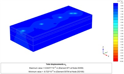
Fig. 6Horizontal displacement distribution cloud map
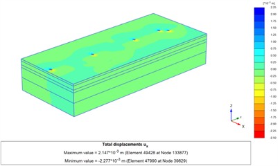
Fig. 7 presents the typical curves of horizontal displacement (, ) for the pile shafts near the bridge pile foundation after excavation reaches the bottom of the working well pit. The maximum horizontal displacement values of the pile shafts are summarized in Table 1. Due to the excavation and unloading effects from the working well, intermediate wells, and receiving well, the bridge pile foundation experiences horizontal displacements in both the transverse and longitudinal bridge directions. Specifically, the D2L pile shaft exhibits the largest transverse bridge direction displacement (), with a maximum value of 0.05079 mm. On one side of W4, the D6R pile shaft shows the largest longitudinal bridge direction displacement (), with a maximum value of –0.07661 mm.
Fig. 8 presents the typical distribution curves of horizontal displacements (, ) for the pile bodies of the bridge pile foundations on both sides during the pipe jacking construction of the sewage pipe. The maximum horizontal displacements of the pile bodies are summarized in Table 2. During the pipe jacking process, the bridge pile foundations experience horizontal displacements in both the transverse and longitudinal directions of the bridge. Specifically, on the side adjacent to W3, the D4 pile body exhibits the largest transverse horizontal displacement, with a maximum value of 0.2381 mm. Similarly, on the same side of W3, the D4 pile body also shows the largest longitudinal horizontal displacement, with a maximum value of 0.8124 mm.
Analysis indicates that throughout the entire process of the sewage pipe project, from the excavation of the working well to the pipe jacking construction, the impact on the adjacent bridge piers and pile foundations is minimal. Both the piers and the pile foundations remain in a safe condition.
Fig. 7Typical curves of horizontal displacement of piles during the excavation process
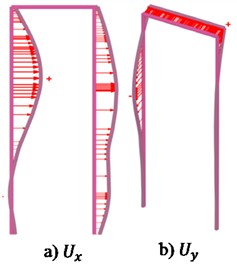
Fig. 8Typical distribution curve of horizontal displacement of piles during pipe jacking advance
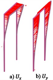
Table 1Summary of the maximum horizontal displacement of the pile body
Pile | Largest transverse bridge direction displacement / mm | Largest longitudinal bridge direction displacement / mm |
D1 | 9.236×10⁻³ | –5.16×10⁻³ |
D2 | 0.05314 | 0.02954 |
D3 | 5.126×10⁻³ | 9.631×10⁻³ |
D4 | –0.0314 | –0.05631 |
D5 | –0.0123 | –0.07416 |
D6 | –0.0489 | 0.04896 |
Table 2Summary of the maximum horizontal displacement of piers
Pile | Largest transverse bridge direction displacement / mm | Largest longitudinal bridge direction displacement / mm |
D1 | 0.0150 | 0.0023 |
D2 | –0.012365 | –0.0315 |
D3 | 0.6254 | –1.2033 |
D4 | 0.1632 | 0.2136 |
D5 | 0.0984 | 0.1684 |
D6 | 0.0674 | –0.0456 |
5. Conclusions
This study employs a finite element model to systematically evaluate the impacts of sewage pipeline construction on adjacent bridge pile foundations. The conclusions can be drawn as:
1) The excavation of the foundation pit for the sewage pipeline working well has a minimal impact on the adjacent bridge foundation. Specifically, the maximum transverse horizontal displacement of the bridge pile foundation is 0.05314 mm, and the maximum longitudinal horizontal displacement is –0.07416 mm. These displacements indicate that the bridge pile foundation remains in a safe condition.
2) The pipe jacking construction of the sewage pipeline also has a minimal impact on the adjacent bridge foundation. During this process, the maximum transverse horizontal displacement of the pile foundation is –0.2381 mm, and the maximum longitudinal horizontal displacement is 0.8124 mm. These results confirm that the adjacent bridge pile foundation remains in a safe state.
Future research should focus on three directions: (1) Developing IoT-enabled real-time monitoring systems integrating distributed fiber optic sensing with our FEM model for dynamic risk; (2) Establishing standardized construction disturbance thresholds for different geological conditions through big data analysis; (3) Creating digital twin platforms combining BIM and geotechnical models for virtual construction rehearsal.
References
-
C. Zou, X. Li, C. He, and S. Zhou, “An efficient method for estimating building dynamic response due to train operations in tunnel considering transmission path from source to receiver,” Computers and Structures, Vol. 305, p. 107555, Dec. 2024, https://doi.org/10.1016/j.compstruc.2024.107555
-
Z.-Y. Tao, C. Zou, G.-R. Yang, and Y.-M. Wang, “A semi-analytical method for predicting train-induced vibrations considering train-track-soil and soil-pile-building dynamic interactions,” Soil Dynamics and Earthquake Engineering, Vol. 167, p. 107822, Apr. 2023, https://doi.org/10.1016/j.soildyn.2023.107822
-
L. Cao, X. Li, Z. Li, J. Liu, J. Li, and X. Lv, “Influence of drainage flow velocity on microscopic cohesive soil erosion and macroscopic road collapse evolution: A case study in Beijing, China,” Engineering Failure Analysis, Vol. 164, p. 108698, Oct. 2024, https://doi.org/10.1016/j.engfailanal.2024.108698
-
J. Ren, Y. Liu, P. Yu, Y. Zhang, and D. Li, “The influence of fines content on ground collapse due to internal erosion of sand-fines mixtures around defective pipes,” Engineering Failure Analysis, Vol. 165, p. 108810, Nov. 2024, https://doi.org/10.1016/j.engfailanal.2024.108810
-
Z. Dai, L. Peng, and S. Qin, “Experimental and numerical investigation on the mechanism of ground collapse induced by underground drainage pipe leakage,” Environmental Earth Sciences, Vol. 83, No. 1, Dec. 2023, https://doi.org/10.1007/s12665-023-11344-w
-
X. Li, R. Chen, L. Liu, C. Zhou, and B. Bate, “A non-Darcy flow CFD-DEM method for simulating ground collapse induced by leakage through underground pipeline defect,” Computers and Geotechnics, Vol. 162, p. 105695, Oct. 2023, https://doi.org/10.1016/j.compgeo.2023.105695
-
S. Indiketiya, P. Jegatheesan, and P. Rajeev, “Evaluation of defective sewer pipe-induced internal erosion and associated ground deformation using laboratory model test,” Canadian Geotechnical Journal, Vol. 54, No. 8, pp. 1184–1195, Aug. 2017, https://doi.org/10.1139/cgj-2016-0558
-
F. Tan, W. Tan, F. Yan, X. Qi, Q. Li, and Z. Hong, “Model test analysis of subsurface cavity and ground collapse due to broken pipe leakage,” Applied Sciences, Vol. 12, No. 24, p. 13017, Dec. 2022, https://doi.org/10.3390/app122413017
About this article

The authors have not disclosed any funding.
The datasets generated during and/or analyzed during the current study are available from the corresponding author on reasonable request.
The authors declare that they have no conflict of interest.
