Abstract
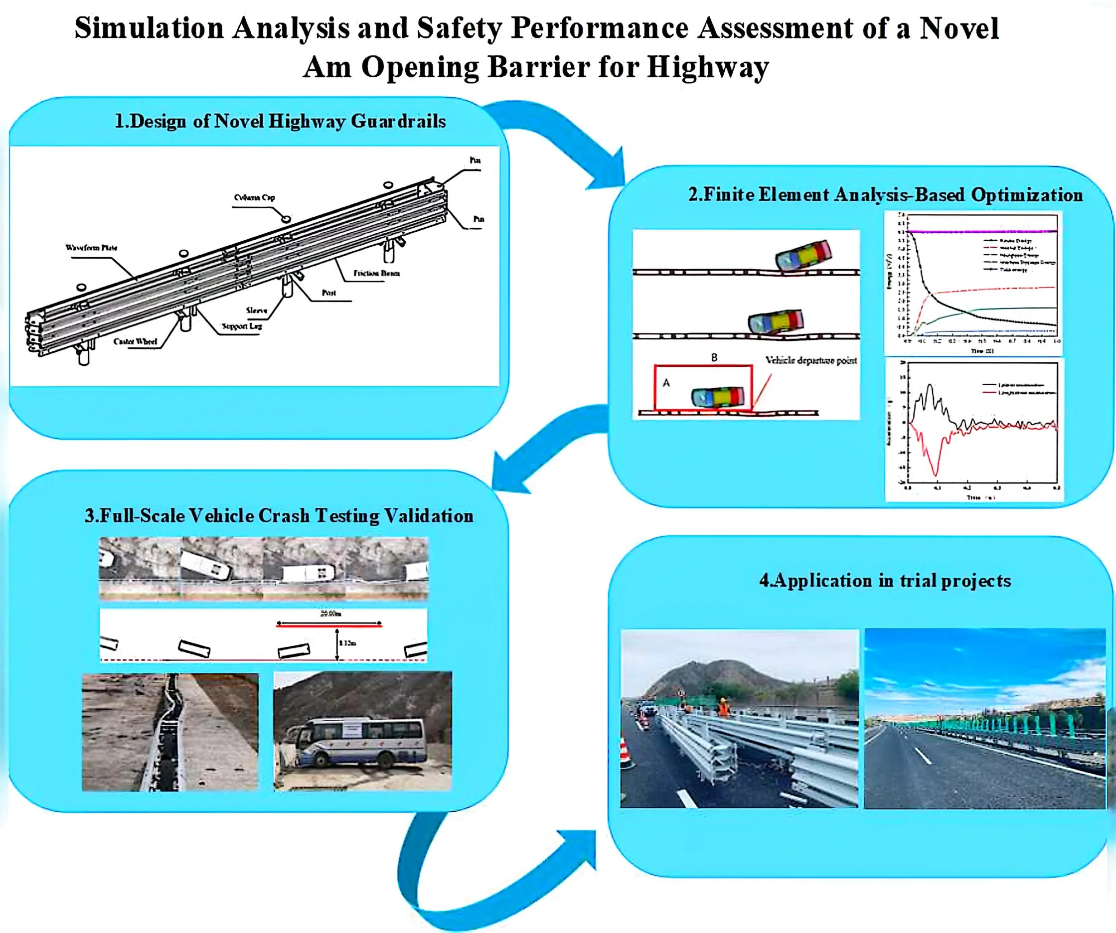
To address the need for quick opening, easy mobility, and convenient maintenance of barrier in highway central medians, a novel Am rotatable open barrier has been designed. Based on guardrail safety performance evaluation standards, a finite element model of the vehicle-guardrail interaction is established for collision simulations to validate the adequacy of the new guardrail structure. In the meantime, full-scale vehicle crash tests are conducted to assess the safety performance of the proposed open guardrail. The results demonstrate that safety performance metrics, including vehicle post-collision acceleration, maximum dynamic inclination, maximum lateral dynamic deformation, and displacement extension values, meet standard requirements in both simulations and real-world validations. Additionally, the vehicle doesn’t penetrate, overturn, or ride over the barrier, and no rollover occurred. This indicates that the newly designed barrier not only fulfills the functions of quick opening and easy mobility but also provides excellent blocking and guiding capabilities, contributing to the enhanced safety and operational efficiency of highway service.
Highlights
- Computational Modeling: We developed a comprehensive finite element model using LS-DYNA explicit dynamics software, rigorously validated through energy conservation criteria (hourglass energy <5%, total energy variation <1%).
- Experimental Validation: Full-scale collision tests confirmed the simulation accuracy, with critical safety parameters - including peak vehicle acceleration (≤20g), dynamic inclination angle (<25°), and lateral deformation (≤1.5m) - demonstrating full compliance.
- Framework Development: The study establishes a validated methodology combining computational simulation and physical testing for guardrail structural optimization.
- Practical Implementation: Field trials demonstrated 40% faster deployment compared to conventional barriers, significantly enhancing operational efficiency in maintenance and emergency scenarios.
1. Introduction
The total mileage of China's highway network has experienced a consistent increase in recent years. By the end of 2020, the total mileage reached 161,000 km, positioning China at the global forefront of highway development [1]. However, with the expansion of the highway network and the rising number of motor vehicles, there has been a notable upward trend in highway traffic safety accidents annually. A significant proportion of these accidents is attributed to collisions between vehicles and highway guardrails on both sides. Available data indicates that vehicle-guardrail-related traffic accidents account for approximately one-third of the total number of accidents [2]. The prevailing design paradigm of existing opening guardrails places emphasis on operational convenience, often compromising their guidance and collision-avoidance performance [3]. This design oversight has the potential to result in severe accidents, particularly when vehicles cross the central median and collide with opposing traffic. As a result, the rational design of guardrail structures has become very paramount importance for highway network.
Researchers globally have dedicated extensive efforts to enhancing the structural integrity of the target components, with substantial investigations focusing on both topological optimization methodologies and high-fidelity finite element numerical simulations. Driemeier et al. [4] employed the finite element method to conduct collision simulation tests, evaluating the performance of W-beam guardrails in terms of energy absorption and the vehicle's return-to-road angle. Hazwan et al. [5] conducted experimental and computational investigations of delamination failure in end-notch flexure specimens under three displacement rate conditions. The numerical simulations conducted demonstrated a strong correlation with experimental data, exhibiting a coefficient of determination () exceeding 0.93 in load-displacement curve validation. Yao et al. [6] proposed a novel type of assembled rolling guardrail and developed a numerical model of vehicle collisions with the guardrail using LS-DYNA. The performance of a beam-type guardrail, a post-type guardrail, an assembled guardrail, and the assembled rolling guardrail was evaluated. The results indicated that the assembled rolling guardrail meets the specified requirements, enhances construction efficiency, and outperforms the other two types of guardrails in terms of performance. Ismail et al. [7] established a numerical framework for cone-cylinder intersection analysis by employing the elastic-perfectly plastic constitutive model of Hiduminium alloy (HE-15). Through parametric finite element simulations, they quantified buckling strength enhancement across varied stiffener geometries while concurrently verifying methodological fidelity through constitutive relationship validation. He et al. [8] utilized LS-DYNA, HyperMesh, and other finite element software to simulate the collision between a vehicle and a guardrail. The vehicle state and guardrail deformation during the collision process were simulated and analyzed. Additionally, the changes in guardrail deformation, vehicle acceleration, and energy under varying collision speeds and angles were investigated. In a subsequent study, Ben-Bassat et al. [9] investigated the influence of key road parameters, including shoulder width, the presence of a guardrail, and road curvature, as independent variables, and driver behavior, such as speed, lane position, and visual pupil area, as dependent variables. The study demonstrated that the guiding function of the guardrail plays a decisive role in influencing the driver's sense of safety. Sun Xianglong et al. [10] developed an easy-open central median crash guardrail and established guardrail models by using finite element software HyperMesh and LS-DYNA. Collision simulations under standard conditions were conducted to analyze and evaluate the results. Mohd et al. [11] systematically investigated the buckling failure mechanisms of stiffened cylindrical shells under combined axial compression-external pressure loading using finite element analysis. Their study elucidated the governing influence of geometric imperfection topologies on the structural load-bearing capacity through parametric FE modeling. Atahan et al. [12] conducted the collision simulation tests performed on the 12-metre bent guardrail end treatment by using the finite element method, which comprehensively assessed the collision performance of the guardrail and provided optimization recommendations based on the experimental results. Soliman et al. [13] developed the finite element model of the ET-Plus guardrail, and validated by using vehicle models in collision simulations at speeds ranging from 97 km/h to 113 km/h, which demonstrated that the ET-Plus FE model can replicate energy absorption mechanisms with its high-quality mesh, thereby enabling safety researchers to study the performance of the ET-Plus terminal in various collision scenarios. Neves et al. [14] performed finite element simulations of the collision behavior of flexible and concrete guardrails with light vehicles, examining the failure limits of the guardrail bolt connections and their impact on collision outcomes, which suggested that the flexible guardrails exhibit superior safety performance in comparison to their concrete counterparts. Kim et al. [15] further advanced vehicle collision simulations by utilizing finite element analysis (FEA) to investigate the interaction between reinforced concrete guardrails and bridge decks. This study examined the stability of vehicle trajectories during collisions, revealing notable disparities in stress distribution and failure modes when considering the bridge deck, as opposed to scenarios devoid of it. Zheng et al. [16] established three vehicle-guardrail finite element models and simulated the collision behavior of rotating guardrails, three-wave guardrails, and concrete guardrails under the same protective level. The real-vehicle collision tests demonstrated that the newly designed guardrail offers superior protective performance. Yin et al. [17] design of a novel type of separated waveform beam guardrail (SWG) incorporated bolted independent columns. A comparative analysis was conducted between the novel SWG and the traditional waveform beam guardrail (TWG) using the finite element simulation method. The findings revealed that the performance of the novel SWG surpassed that of the TWG.
Furthermore, the substantial full-scale vehicle collision tests have been conducted with guardrails being evaluated based on established safety assessment standards. These studies analyzed the performance and safety of guardrails under various collision scenarios, ultimately assessing their safety performance. Zheng et al. [18] designed a framework-type open guardrail structure and conducted safety performance evaluations based on the results of full-scale vehicle collision tests. The results indicated that the guardrail achieved an A-level protection rating. In a similar vein, Yu et al. [19] conducted full-scale vehicle collision tests on the proposed open guardrail and assessed the safety performance of the central median barrier based on the test results. The results demonstrated that the designed guardrail can meet the safety performance requirements for SA-level central median barriers as specified in the standard. Yue et al. [20] developed an SB-level multifunctional guardrail and conducted full-scale vehicle collision tests with small and medium-sized passenger cars, and large trucks. Their results indicated that the SB-level multifunctional guardrail satisfied the established evaluation standards. Zhang et al. [21] designed a movable steel barrier with grade SB light composite corrugated beam. In accordance with the collision conditions specified for the SB guardrail in the safety performance evaluation standard, the guardrail's blocking, guiding, and buffering functions were verified through finite element simulations and full-scale vehicle collision tests. The results indicated that the safety performance of the SB guardrail meets the requirements of the safety performance evaluation standard. Jiang et al. [22] proposed a new type of recycled foam concrete crash guardrail (RFCG), and its energy absorption and protective performance were evaluated through full-scale model crash tests and numerical simulations. The results demonstrated that the RFCG exhibits superior energy absorption capabilities and causes less damage to the vehicle compared to the standard guardrail. Zou et al. [23] analyzed the probability of potential collisions across various road and guardrail scenarios using available crash data. It was demonstrated that guardrails are effective in reducing the percentage of hazardous collisions, thereby contributing to a more transparent assessment of the safety effectiveness of road guardrails.
In summary, these scholars have analyzed the impact of guardrail structure and materials on protection performance through theoretical analysis, simulations, and full-scale vehicle collision tests, among other methods. The object of these studies was to optimize guardrail structure and enhance its collision avoidance capabilities and overall safety. To address the practical requirements of highway central divider opening guardrails – such as rapid deployment, ease of movement, and straightforward maintenance – along with the narrower central divider characteristics common in China, a novel rotatable opening central divider guardrail is proposed in this paper. The current Guardrail Safety Performance Evaluation Standard [24] for Am-level guardrail testing regulations is adhered to verify the reasonableness of the new guardrail structure, and finite element analysis is employed for collision simulations. Simultaneously, the results are analyzed through full-scale vehicle collision tests to assess the safety performance of the developed guardrail, providing a foundation for its promotion and application in practical projects.
2. Structural design of new am-level hinged opening guardrails
2.1. Design theories of new guardrails
The actions that are implemented on highway traffic safety facility structures are categorized based on their temporal variability into permanent actions, variable actions, and accidental actions. Among these, accidental actions refer to those that may not necessarily occur during the designated reference period, but, if they do, exhibit extremely large magnitudes and short durations. Vehicle collision loads are classified as accidental actions [25]. According to the aforementioned definition, the formula for the combination of their effects is expressed as follows:
where, represents the design value of effect combination under accidental combinations at the ultimate limit state; denotes the frequent value coefficient of the dominant variable action; corresponds to the quasi-permanent value coefficient of the -th variable action; signifies the characteristic value of the action effect from the accidental action (vehicle collision load).
When a collision occurs at the standard section of a guardrail, the characteristic resistance of the guardrail to lateral loads can be determined using the yield-line method, with its expression formulated as:
The critical length for the formation of yield lines should be specified as:
where, denotes the effective height (m) of the guardrail; represents the critical length (m) of the yield-line failure mechanism; corresponds to the longitudinal length (m) of collision load distribution; signifies the bending moment capacity (kN·m) of the guardrail about its vertical axis; refers to the additional bending moment capacity (kN·m) at the guardrail top excluding (i.e., supplementary to the main beam); and defines the bending moment capacity (kN·m) of the cantilever-type guardrail about the bridge’s longitudinal axis.
The primary material of the novel guardrail is Q235 steel, a common carbon structural steel classified as Grade 235 with a yield strength of 235 MPa and a tensile strength ranging from 375 to 500 MPa. These properties enable Q235 steel to meet the deformation and energy absorption requirements of corrugated beam guardrails. Q235 steel exhibits a balanced combination of toughness (elongation after fracture ≥ 26 %) and strength, ensuring structural rigidity while mitigating brittle fracture risks, thereby conforming to the technical specifications outlined in Highway Corrugated Steel Guardrails [26]. Compared to high-strength steels (e.g., Q700NH), Q235 steel offers advantages in lower raw material costs, abundant availability, and elimination of complex heat treatment processes, further reducing production expenses.
During collision testing, the stress remained below the yield strength of 235 MPa. Based on Hooke's Law and the yield criterion, when the stress is below the yield strength (), the material behaves elastically, yielding the relationship:
where is strain andis the elastic modulus.
The Eq. (4) reveals a linear relationship between stress () and deformation (). The standards stipulate that the serviceability limit state design of traffic safety facility structures primarily considers ensuring structural deformation does not exceed permissible limits. Whether the maximum internal stress generated in the material remains within its safe stress range is indirectly reflected through the control of structural deformation. Consequently, the safety analysis is conducted based on the parametric requirements specified in the standards for post-collision performance indicators.
In accordance with the dimensional specifications stipulated in the Traffic Safety Facilities Design Code [25], the designed Am-level guardrail components must conform to the following requirements: the width, height, and thickness of the corrugated beam shall be 506 mm × 85 mm × 3 mm; the diameter and wall thickness of the posts shall be 140 mm × 4.5 mm, while no dimensional constraints are imposed on the friction beams. Since the designed guardrail adheres to these standard specifications, the dimensions and materials of all guardrail components are summarized in Table 1.
Table 1Structural parameters of actual barrier
Parametric | Guardrail | Three-wave beam plate | Support post | Friction beam | Caster wheel |
Length (mm) | 42000 | 4135 | – | 5990 | 630 |
Width (mm) | 500 | 506 | – | 50 | 380 |
Height (mm) | 950 | 85 | 1200 | 50 | 130 |
Diameter (mm) | – | – | 140 | – | – |
Thickness (mm) | – | 3 | 4.5 | 3 | – |
Material | Q235 | Q235 | Q235 | Q235 | Q235 |
2.2. Structural configurations of new guardrails
The openable guardrail segments, installed at median openings in highway systems, are movable safety structures designed to permit emergency access for specialized vehicles (e.g. incident response and medical emergency units) and temporary traffic flow adjustments during road maintenance. The following operational and performance deficiencies have been identified in current Am-level openable guardrail systems, including pre-stressed and frame-type structures:
1) The operation and maintenance of the system is a labour-intensive process. Existing openable guardrails in China employ a single-section opening mechanism, necessitating sequential relocation of individual sections to designated positions. The process is time-consuming, dependent on specialized tools, and complicates routine maintenance.
2) The interface between the existing guardrail and the main section required complex adjustments. Transition interfaces necessitate customized on-site design, particularly for compatibility with conventional corrugated beam guardrails, which require overlapping and encapsulation with fixed guardrail terminals.
3) The issue of inadequate crashworthiness and the presence of post-impact hazards is a matter of concern. The system's multiple interconnected components are susceptible to excessive deformation under collision, thereby compromising its impact resistance. In the aftermath of a collision, structural failure may precipitate the detachment of components, thereby generating airborne projectiles and concomitantly augmenting the risk of secondary collisions.
Fig. 1Previously used Am-level structural guardrails
a) Pre-stressed structure guardrails
b) Frame-type structure guardrails
A novel triple-corrugated beam modular openable guardrail has been developed through comprehensive consideration of protection performance, transition rationality, innovative opening mechanisms, structural visibility, and operational reliability. The design references the widely implemented triple-corrugated beam modular configuration while addressing its limitations.
The newly designed structure of rotatable open-type central divider guardrail, as shown in Fig. 2, consists of an upper three-waveform beam plate, which is primarily employed for the protection of medium and large vehicles, while the lower portion incorporates a friction beam, mainly used to protect minibuses and prevent collisions with the minibus collision column tripping block. The system employs an integrated modular design, facilitating component-based manufacturing and transportation, while enabling modular maintenance, repair, and replacement to enhance operational efficiency. The overall beam structure is characterized by its good permeability, which facilitates snow drainage.
Fig. 2The new type of rotatable and openable barrier
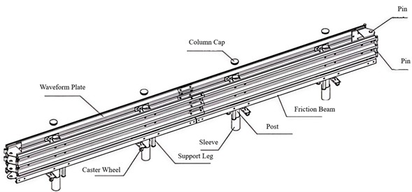
The guardrail incorporates a pluggable and removable structural configuration, where adjacent units are interconnected via pins to achieve cohesive integration with conventional waveform beam guardrails. The design is distinguished by the elimination of redundant structural components, a measure that is intended to prevent secondary accidents caused by detached elements during collision events. Each guardrail section is equipped with a caster-mounted height-adjustable leg mechanism at its base. The vertical displacement of the lower sleeve assembly is actuated by a dual-threaded screw rod with opposing threads positioned above the mechanism. This configuration facilitates a double pitch displacement per revolution during height adjustment, thereby enabling rapid operational efficiency through electric torque wrench actuation. The adjustable legs of the guardrail system have been designed to compensate for road surface irregularities, while ensuring that the guardrail height remains uniform during the installation process. Movement of the guardrail after opening is achieved by support components and universal wheels.
Fig. 3Bi-directional rotation schematic of the guardrail
a) Post extraction
b) Post fixation
c) Caster wheel lowering
d) Pin shaft removal
e) Rotation opening
f) Rotation closing
g) Post lowering
h) Caster wheel raising
The pluggable and removable structure allows for rapid opening and closing, with a 16-meter opening being completed in approximately 5 minutes, which surpasses the requirements of the Traffic Safety Facilities Design Code [25], which specifies a 10-meter opening within 10 minutes. Activation of the longitudinal rotational linkage mechanism enables the concurrent realization of safety protection functionality and bi-directional rotation capacity for individual or grouped guardrail sections, as detailed in the operational sequence illustrated in Fig. 3.
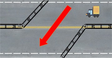
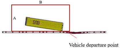
The specified length can be opened and the angle rotated according to the practical requirements, with the rotated guardrail additionally serving the purpose of assisting in road closure and guiding vehicles, as depicted in Fig. 4.
Fig. 4Schematic of bidirectional rotation of barrier
3. Conditions of crash and evaluation criteria
To ensure overall road safety and coordination, the crashworthiness level of the opening guardrail must be aligned with that of other components of the central reservation guardrail. The serviceability limit state of infrastructure is typically defined by structural deformation, cracking, or vibration parameters that exceed permissible thresholds for operational or durability requirements. In the context of traffic safety infrastructure, however, the serviceability limit state design is primarily governed by the restriction of structural deformation to impermissible limits [25]. In accordance with the relevant provisions of the Guardrail Safety Performance Evaluation Standard [24], the primary parameters and acceptable tolerances for the collision conditions of the Am-level guardrail are outlined in Tables 2 and3. The safety performance indicators for the central divider opening guardrail are as follows:
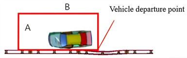
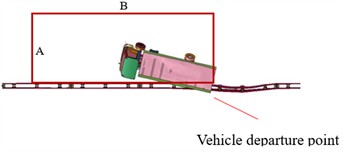
(1) Guiding Function: It is required that the vehicle does not overturn following a collision. The trajectory of the vehicle's wheels after leaving the starting point must satisfy the condition of remaining within the guiding framework.
(2) Buffering Function: The upper limits for both the longitudinal and transverse components of the occupant's collision velocity must not exceed 12 m/s. Similarly, the upper limits for both the longitudinal and transverse components of the occupant's post-collision acceleration must not surpass 200 m/s².
(3) Restraint Function: The test rail must be capable of restraining the test vehicle from crossing, overturning, or overriding. Additionally, the components of the test rail and their attachments must not intrude into the passenger compartment of the vehicle.
Table 2Key parameters of vehicle collision
Vehicle type | Total mass of the vehicle | Velocity | Angle | Energy |
Light passenger vehicle | 1.5t | 100km/h | 20° | – |
The medium bus | 10t | 60 km/h | 20° | 160kJ |
The medium truck | 10t | 60 km/h | 20° | 160kJ |
Table 3Permissible tolerances for vehicle parameters
Vehicle type | Tolerance of quality | Tolerance of speed | Tolerance of Collision Angle |
Light passenger vehicle | –75-0 kg | 0-3 km/h | 0°-1.5° |
The medium bus | 0-300 kg | 0-3 km/h | 0°-1.5° |
The medium truck | 0-300 kg | 0-3 km/h | 0°-1.5° |
4. Modelling simulation and result analysis
Due to the high costs associated with full-scale crash testing of real vehicles, while finite element simulation offers a more cost-effective, convenient, and easily repeatable alternative, it is utilized to reduce the necessity for real vehicle crash tests and, consequently, to lower overall costs. To minimize the number of full-scale crash tests, the structure of the new guardrail and the adequacy of its component dimensions are evaluated by finite element simulation. This approach is employed to analyze whether the simulation results satisfy the relevant standard requirements.
4.1. Collision hypothesis
Given the complexity of the dynamic problems involved in the collision between the vehicle and the guardrail, it is acknowledged that the computer simulation and analysis process may not fully align with the actual conditions. To enhance computational efficiency and ensure the reliability of the simulation results, the following assumptions have been made regarding the collision model in this study:
(1) Emergency maneuvers by the driver, such as steering, are not considered.
(2) Vertical acceleration of the vehicle is neglected.
(3) Bolted connections between the real guardrails may be simplified or ignored, depending on their influence on the simulation results.
(4) The lateral acceleration of the vehicle is assumed to be zero when the collision occurs parallel to the crash barrier.
(5) The position of the vehicle's center of gravity is assumed to remain unchanged during the collision process.
4.2. Finite element modelling of automobiles
The deformation of the vehicle during the collision with the guardrail, as well as the morphology and trajectory after the collision, is contingent upon the accuracy of the simulation model. Therefore, the vehicle model must be established in accordance with the following principles:
(1) The vehicle model specifications and overall dimensions should conform to the specifications outlined in the relevant standards.
(2) The total mass and mass distribution of the model must be consistent with the specifications and the actual vehicle.
(3) The choice of cell type, grid density, and material properties in the vehicle model should meet the required standards.
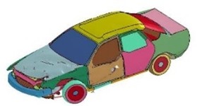
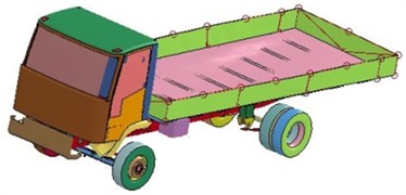
To ensure that the simulation results of the vehicle-guardrail collision more closely align with real conditions, finite element models for small buses, medium buses, and medium trucks have been developed based on the existing standards for vehicles in China, as well as the actual parameters of the vehicles. These models are presented in Fig. 5. The three vehicle models comply with the vehicle-related requirements specified in the Guardrail Safety Performance Evaluation Standards [24], and the parameters for each model are provided in Table 4.
Table 4Finite element model parameters for vehicles
Parametric | Light passenger vehicle | The medium bus | The medium truck |
Length (mm) | 4570 | 8500 | 7850 |
Width (mm) | 1780 | 2450 | 2480 |
Height (mm) | 1300 | 3000 | 2400 |
Mass (t) | 1.5 | 10 | 10 |
Modules (count) | 51117 | 74452 | 29080 |
Fig. 5Vehicle finite element model
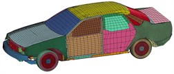
a) Light passenger vehicle
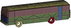
b) The medium bus
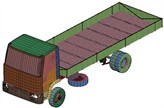
c) The medium truck
4.3. Finite element modelling of guardrail
The accuracy of the simulation results would be significantly influenced by finite element model established for the guardrail. Therefore, the guardrail model is constructed in accordance with the following principles:
(1) The guardrail model and the corresponding vehicle are required to share the same coordinate system.
(2) The length of the guardrail model must align with the length specified in the relevant standards.
(3) Appropriate connection methods between the components of the guardrail model should be selected based on their influence on the simulation results.
(4) The cell type, grid density, and material properties for each component of the guardrail model must meet the specified requirements.
The guardrail model is constructed according to actual dimensions. In accordance with the Guardrail Safety Performance Evaluation Standard [21], the effective length of the opening guardrail for the central divider must not be less than 40 meters. The structure and parameters of the finite element model of the guardrail are presented in Fig. 6 and Table 5, respectively.
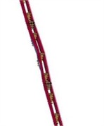
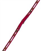
Fig. 6Barrier finite element model
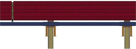
a) Diagram of the guardrail front view
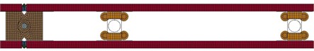
b) Diagram of guardrail top view
Table 5Parameters of barrier in finite element model
Parametric | Guardrail | Three-wave beam plate | Support post | Friction beam |
Length (mm) | 42000 | 4135 | – | 5990 |
Width (mm) | 500 | 506 | – | 50 |
Height (mm) | 950 | 85 | 1200 | 50 |
Diameter (mm) | – | – | 140 | – |
Thickness (mm) | – | 3 | 4.5 | 3 |
Material | Q235 | Q235 | Q235 | Q235 |
In the actual installation of the guardrail, these holes are typically drilled into the concrete pavement, with the columns inserted into them for anchoring. These columns are then fixedly connected to one another, while the concrete pavement primarily serves to provide constraints. To enhance computational efficiency, the road surface is not modeled during the simulation process. However, the fixed connection between the columns and the concrete road surface is considered in accordance with real conditions, and constraints are appropriately applied to the lower portion of the columns.
4.4. Settings for collision contact
The collision process between a vehicle and a guardrail primarily involves their mutual contact. However, upon collision, the internal components of the guardrail also experience mutual impact. In addition to the initial contact between the guardrail and the vehicle, new points of contact arise, making the actual contact scenario highly complex [27]-[28]. Therefore, establishing a reasonable contact model is essential. Based on relevant collision simulation experience, the contact interactions between the vehicle and the guardrail, as well as between the different components of the guardrail, are defined in this study as listed in Table 6.
Table 6Contact types in vehicle-barrier collision systems
Interaction | Contact type |
Interaction Between the Guardrail Plate, Block, and Pos | Contact Automatic Single Surface |
Interaction Between the Vehicle and the Guardrail | Contact Automatic Nodes to Surface |
Interaction Between the Wheels and the Road Surface | Contact Automatic Surface to Surface |
Vehicle-guardrail interaction | Contact automatic single surface |
Interaction Between the Column and the Soil | Contact Automatic Surface to Surface |
4.5. Analysis of simulation results
In the event of a collision, the deformation of system is considered to include the energy absorption capacity of the guardrail, providing essential parameters that facilitate improved design and material selection. The guiding function pertains to the ability of system to restore normal traveling conditions post-collision, while simultaneously assisting in the prevention of secondary collisions. This function must be evaluated in conjunction with the collision outcomes observed for both small and medium-sized vehicles.
4.5.1. Validation of finite element model
To verify the validity of the car-guardrail model, the criteria for model verification, as outlined below, have been applied. These criteria are based on the relevant requirements of the Technical Procedure for Simulation and Evaluation of Safety Performance of Guardrails [29]:
(1) The total energy change in the crash simulation should not exceed 5 %.
(2) The leakage energy must be less than 5 % of the total energy.
(3) No nodes should eject.
(4) No negative volume cells should be present.
The collision system between the car and the guardrail has been simulated, and the results indicate that there were no instances of node ejection or negative volume cells during the collision process. The energy change curve is presented in Fig. 7. Upon examination, it is evident that energy conservation within the entire collision system is maintained, with kinetic energy decreasing while internal energy increases. The various energy curves exhibit smooth transitions without singularities. The hourglass energy for the car model system is 4.83 %, and the total energy change in the collision simulation is 0.95 %, which is below the threshold specified in the technical requirements. Therefore, it can be concluded that the simulation results obtained from the “car-guardrail” collision model are valid.
4.5.2. Light passenger vehicle crashes into new opening guardrail
As shown in Fig. 8, upon impact with the guardrail at a velocity of 100 km/h, the front of the vehicle undergoes deformation primarily to dissipate the collision energy. Contact with the guardrail is initiated at 0.108 s, the steering is engaged at 0.18 s, and full contact with the guardrail is achieved at 0.49 s.
Fig. 7Energy curves of collision
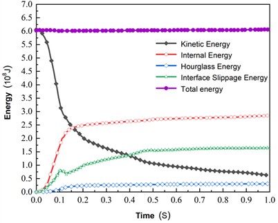
Fig. 8The car driving track
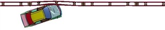
a)0.108 s
b)0.18 s
c)0.49 s
Throughout the entire process of extraction, the steering mechanism of the small passenger vehicle rapidly detached, with no observable deformation in the rear. The vehicle trajectory remained within the designated extraction frame. Subsequent to the collision, no substantial damage or component detachment was observed in the vehicle, which maintained its structural integrity. The guardrail exhibited minor bending deformation, with all components remaining intact without detachment, thereby preserving the overall structural integrity and effectively guiding the vehicle, as illustrated in Fig. 9.
Fig. 9Post-collision damage characteristics of light passenger vehicle and guardrails
The friction beam plays a crucial role in preventing the small bus from colliding with the column trip block. As a result, the small bus neither crossed, rode over, nor rolled over the opening guardrail. The maximum lateral displacement of the guardrail was recorded at 0.24 m. The results indicate that the vehicle fulfills its guiding function effectively, thereby meeting the guardrail collision standard evaluation criteria.
In accordance with the provisions outlined in the Guardrail Safety Performance Evaluation Standard [24], it can be observed that the post-crash acceleration of the occupants is comparable to that of the vehicle itself. The original curve of the vehicle’s center of mass acceleration, measured at 10 ms intervals in each direction, is shown in Fig. 10. From Fig. 10, it reveals the presence of multiple peaks in post-crash acceleration, with the maximum longitudinal acceleration at 10.3 g and the maximum transverse acceleration at 8.15 g. Notably, both are below the stipulated maximum value of 20 g.
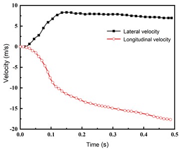
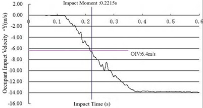
The original curve of occupant collision velocity is presented in Fig. 11. From this figure, it can be inferred that both the longitudinal and transverse components of occupant collision velocity remain below 12 m/s. It is evident that all performance indices comply with the prescribed standards, thereby ensuring the anticipated protective effect.
Fig. 10Acceleration in both direction of car
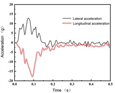
Fig. 11Occupant impact velocity in both direction
4.5.3. Medium bus crashes into new opening guardrail
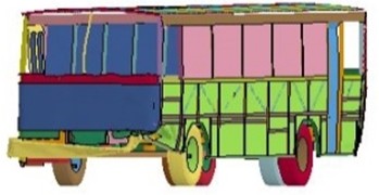
The process of the medium-sized bus colliding with the guardrail at 60 km/h is illustrated in Fig. 12. Due to the substantial mass of the medium-sized bus, the collision area of the guardrail exhibited significant deformation and tilt. It was observed that the front portion of the vehicle made contact with the guardrail, resulting in a maximum transverse deformation of 0.56 m within 0.18 s. The initial collision was completed in 0.41 s, followed by a secondary collision that caused the vehicle's tail to be displaced. Full contact with the guardrail was achieved at 1.03 s, and the vehicle was safely driven away from the guardrail at low speed.
Fig. 12The medium bus driving track
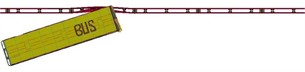
a)0.108 s
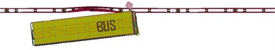
b)0.41 s
c) 1.03 s
Throughout the process of moving out of the three-waveform beam plate, which was specifically designed to effectively manage collision forces, the medium-sized bus did not cross, ride over, or roll over the guardrail. The vehicle's wheel trajectory remained within the guiding frame, demonstrating that the collision resulted in a positive guiding effect. Localized damage was observed in the impact zone of both the guardrail and the medium bus, yet no severe component detachment occurred. The section of the guardrail that had been impacted exhibited marked deformation and tilting, accompanied by localized material failure. However, its structural integrity remained intact without critical components disengaging, thus meeting the evaluation criteria for guardrail collision standards (shown as Fig. 13).
Fig. 13Post-collision damage characteristics of medium bus and guardrails
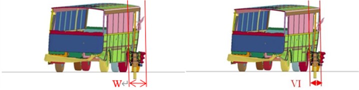
In the context of traffic safety facilities, the maximum lateral dynamic displacement extension value is employed to evaluate the effectiveness of guardrails in absorbing collision energy and ensuring the safety of both the vehicle and its occupants. The maximum dynamic vehicle tilt value serves as an indicator of the vehicle's stability and the degree of tilt experienced under lateral acceleration. The maximum lateral dynamic displacement extension of the guardrail and the vehicle tilt are depicted in Fig. 14. As demonstrated by the results, the maximum lateral dynamic displacement extension of the guardrail is 0.78 m, and the maximum dynamic vehicle tilt is 0.63 m, both of which are below the specified threshold of 3.5 m. Thus, the results meet the requirements of the evaluation indicators.
Fig. 14Maximum dynamic widening distance of lateral deflection and incline-out distance of barrier
4.5.4. Medium truck crashes into new opening guardrail
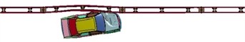
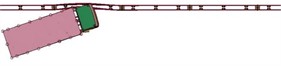
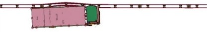
As illustrated in Fig. 15, the process of the medium-sized lorry colliding with the guardrail at 60 km/h is depicted. Due to the substantial mass of the medium-sized lorry, the collision portion of the guardrail exhibited significant deformation and tilt. However, under the guiding influence of the guardrail, the trajectory of vehicle was redirected. It was determined that the front section of the vehicle contacted with the guardrail within 0.125 seconds, resulting in a maximum lateral deformation of 0.47 meters. Within 0.36 seconds, the medium-sized lorry, now positioned parallel to the guardrail, continued its forward motion. Subsequently, at 0.84 seconds, the rear of the vehicle contacted with the guardrail.
Throughout the collision process, the designed structure can effectively guide and protect the vehicle. The medium-sized lorry did not cross, ride over, or pass under the movable guardrail, and no rollover was observed. No significant deformation occurred in the rear section of the vehicle, and the vehicle's wheel track remained within the guiding frame after exiting the point of contact. The truck body exhibited structural integrity post-impact, with no substantial component dislodgement observed. In a similar manner, the guardrail section that had been impacted exhibited visible signs of deformation and tilting, in addition to localized damage. Nonetheless, this did not result in the loss of structural continuity on a large scale, nor did it lead to the dislodgement of any significant components, as illustrated in Fig. 16. The maximum lateral dynamic displacement was recorded at 0.83 m, and the maximum dynamic camber value of the vehicle was 1.22 m, both of which are below the specified limit of 3.5 m, thereby meeting the requirements of the evaluation index.
Fig. 15The medium truck driving track
a)0.125 s
b)0.36 s
c)0.84 s
Fig. 16Post-collision damage characteristics of medium truck and guardrails
5. Full-scale crash test and safety performance evaluation
In accordance with the stipulations set forth in the Safety Performance Evaluation Standard for Guardrails [24]:
(1) The safety performance of new road traffic protection facilities must be evaluated prior to their implementation in highway projects.
(2) The safety performance of highway traffic protection facilities is required to be assessed through full-scale crash testing.
In this study, the safety performance evaluation is conducted using real vehicle full-scale collision tests.
5.1. Test site
The test system at the test site consists of three primary components: the crash plaza, the vehicle acceleration system, and the test inspection system, as shown in Fig. 17.
The collision plaza, designated for testing qualification of real vehicle full-scale collision tests in China, is equipped with both a test guardrail and a data testing site. The site is characterized by its expansive, level terrain, with the road surface conforming to the prescribed standards for highway pavement flatness and roughness. The absence of any obstacles within the site ensures the unimpeded operation of the test vehicle. To achieve the required collision velocity, the test vehicle utilizes an integrated approach that combines electric traction with gravity acceleration methodologies.
The position of the test vehicle’s center of gravity is determined in accordance with the specifications outlined in the “Automobile Quality (Weight) Parameter Determination Method” (GB/T 12674) and the 'Measurement of the Centre of Gravity Position of Two-Axle Road Vehicles' (GB/T 12583). The total mass, overall mass distribution, and center of gravity position of the test vehicle are particularly relevant for the analysis. Deformation and damage to both the guardrail and the vehicle’s operating status are documented using a high-speed video camera, capturing footage from multiple angles.
Fig. 17Test site
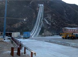
a) The crash plaza
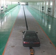
b) The vehicle acceleration system
c) The test inspection system
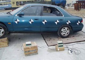
5.2. Test vehicle
The test minibus has a total mass of 1330 kg, with its center of gravity located 585 mm above the ground. The test medium-sized bus has a total mass of 7311 kg, and its center of gravity is positioned 1255 mm above the ground. The test medium-sized lorry has a total mass of 4231 kg, with its center of gravity at a height of 1358 mm from the ground. The vehicle conditions are depicted in Fig. 18.
Fig. 18Test vehicle
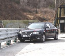
a) Light passenger vehicle
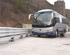
b) The medium bus
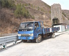
c) The medium truck
5.3. Crash test results and analysis
The results of the real-vehicle collision test consist primarily of collision condition parameters and performance index parameters. The detailed results are provided in Tables 7 and 8. The test results are in compliance with the requirements of the Highway Guardrail Safety Performance Evaluation Standard [21], as well as with the specified test conditions and control accuracy.
Table 7Test results for collision condition parameters
Vehicle type | Total mass of the vehicle (kg) | Velocity (km/h) | Angle (°) |
Light passenger vehicle | 1478 | 101.0 | 20.0 |
The medium bus | 10129 | 62.3 | 20.2 |
The medium truck | 10075 | 61.0 | 20.1 |
As illustrated in Fig. 19, the original change of the buffer performance for the minibus is presented during 10 ms intervals, allowing for the analysis of the trends in the longitudinal and transverse velocity curves of the occupants. It is observed that these trends are essentially identical. During the collision process, the collision velocity between the occupant's head and the occupant compartment is found to be less than 12 m/s in both directions. The maximum longitudinal and transverse accelerations experienced by the minibus occupant after the collision are 95.3 m/s2 and 153.9 m/s2, respectively, which are both below the specified requirement of 200 m/s2, thereby meeting the required standards. It can be concluded that the newly designed rotatable opening-type center median guardrail effectively limits the collision speed and acceleration of the occupant’s head, thus fulfilling the necessary safety criteria.
Fig. 19Raw curve of cushioning performance test
a) Longitudinal component of passenger speed for the vehicle
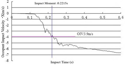
b) Lateral component of occupant speed for the vehicle
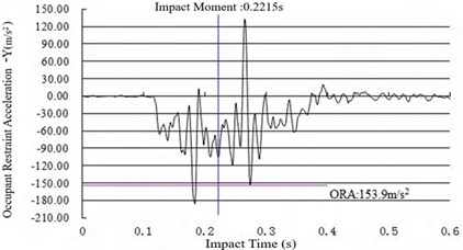
c) Longitudinal component of passenger acceleration for the vehicle
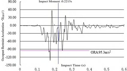
d) Transverse component of occupant acceleration for the vehicle
The driving trajectories of the three vehicles during the test are presented in Fig. 20, with the simulation results of the vehicle driving attitude found to be largely consistent with the test results. Following the collision, the vehicle continued to operate smoothly and returned to its normal driving attitude. The right front section of the test vehicle was deformed due to the collision, but the interior space of the cabin was not significantly compressed, thus ensuring occupant safety. Furthermore, the wheel track of the vehicle remained within the guiding frame after exiting the designated point, and the vehicle did not cross, overturn, or traverse the guardrail post-collision. No rollover occurred, and the guardrail components, along with any detached debris, did not intrude into the passenger compartment. The blocking, buffering, and guiding functions were all successfully fulfilled, thereby ensuring the safety of the vehicle. The guardrail demonstrated effective protective performance.
Table 8Test results for performance indicator parameters
Parametric | Light passenger vehicle | The medium bus | The medium truck |
Maximum lateral dynamic deformation value of guardrail | 0.30 m | 0.85 m | 0.40 m |
Maximum lateral dynamic displacement extents of guardrail | 0.75 m | 1.15 m | 0.70 m |
Maximum dynamic vehicle camber value | – | 0.90 m | 1.05 m |
Equivalent value of maximum dynamic camber of the vehicle | – | 1.10 m | 1.85 m |
Fig. 20The test vehicle driving track
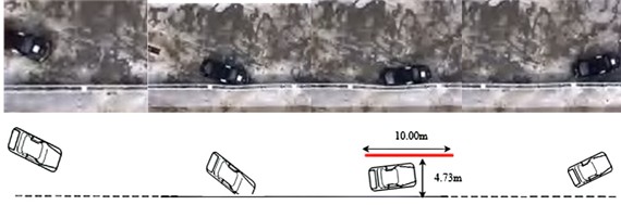
a) The light passenger vehicle driving track
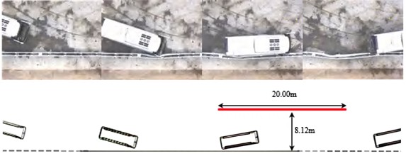
b) The medium bus driving track
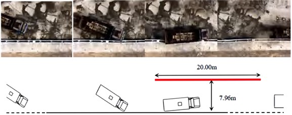
c) The medium truck driving track
The results of the real-vehicle full-scale collision test indicate that the newly developed rotatable open-type guardrail, which incorporates a friction beam structure, effectively prevents any obstruction during the collision process of the test vehicle. The integration of the three-wave beam plate and other components through pin links into a unified system results in minimal deformation upon collision, while simultaneously enhancing the guardrail’s capacity for collision buffering, blocking, and directing the vehicle.
The maximum post-collision acceleration of the occupants, the maximum dynamic camber value of the vehicle, the maximum lateral dynamic deformation of the guardrail, and the displacement extension value, along with other safety performance evaluation indices, all of them satisfy the required standards. Moreover, after the vehicle departed from the designated point, its wheel track remained within the prescribed guide frame. The vehicle did not cross, overturn, or traverse the guardrail post-collision, and no rollover was observed. The test guardrail components, along with any detached elements, did not intrude into the vehicle's occupant compartment, thereby meeting the requirements set forth in the Guardrail Safety Performance Evaluation Standard [24]. Therefore, the implementation of this new Am-level hinged opening guardrails on highways is deemed both feasible and advantageous, contributing to the enhancement of highway safety services and operational efficiency.
5.4. Performance comparison of guardrails
Following the conducting of full-scale vehicle crash tests and the acquisition of the relevant data, a comparison was made between the performance parameters of the proposed guardrail system and those of the existing market product, designated “Am-level truss-type movable guardrails”. The results of this comparison are summarized in Table 9.
Table 9Structural parameters of actual barriers
Term of comparison | Hinged Opening Guardrails | Truss-type movable guardrails | ||||
The medium bus | Light passenger vehicle | The medium truck | The medium bus | Light passenger vehicle | The medium truck | |
Maximum lateral dynamic deformation value of guardrail | 0.85 m | 0.3 m | 0.4 m | 1.25 m | 1.1 m | 1.35 m |
Maximum lateral dynamic displacement extents of guardrail | 1.15 m | 0.75 m | 0.7 m | 1.85 m | 1.65 m | 1.75 m |
Maximum dynamic vehicle camber value | 0.9 m | – | 1.05 m | 1.5 m | – | 1.7 m |
Equivalent value of maximum dynamic camber of the vehicle | 1.1 m | – | 1.85 m | 1.75 m | – | 2.8 m |
As demonstrated in the table, the novel Am-level rotatable openable guardrail exhibited superior performance parameters in comparison to the original “Am-level truss-type movable guardrail” product in full-scale vehicle crash tests, indicating enhanced crashworthiness. Furthermore, post-collision damage assessments of both guardrails and vehicles (shown as Fig. 21) reveal critical distinctions:
The novel guardrail exhibited no redundant structural components, maintained structural continuity with minimal deformation, and eliminated projectile hazards, thereby mitigating secondary collision risks. The vehicle in question exhibited localized indentation and surface abrasion on the left-hand side yet retained its structural integrity with only minor component detachment.
Conversely, the original Am-level truss-type guardrail – constructed with steel tube-dominated frameworks and multiple connecting members – suffered excessive deformation under impact. This design predisposition to component dislodgement resulted in the generation of airborne debris, thereby significantly elevating the potential for secondary accidents. The medium-sized bus that collided experienced severe front bumper deformation, bilateral headlight detachment, and compromised structural integrity with substantial component failure.
Fig. 21Post-collision damage characteristics of guardrails and vehicles
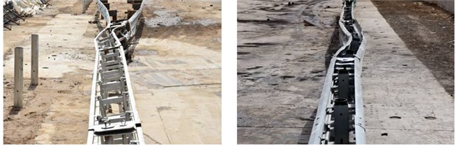
a) Post-collision damage assessments of guardrails
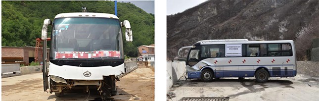
b) Post-collision damage assessments of vehicles
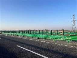
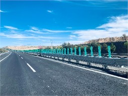
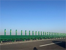
6. Application in trial projects
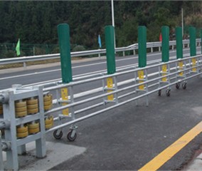
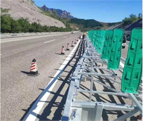
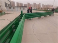
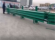
The guardrail system has been implemented in multiple pilot projects. As demonstrated in Fig. 22, the efficacy of the application is evident in the continuous integration between the openable guardrail and the median corrugated beam guardrail. The system has been engineered to ensure a seamless elevation transition, structural continuity, and an aesthetically cohesive visual appearance.
Fig. 22Photo for application of trial project
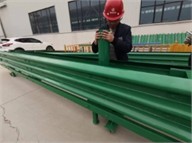
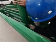
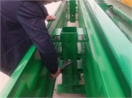
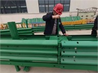
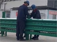
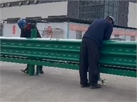
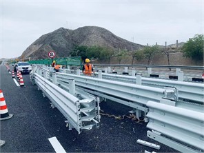
As demonstrated in Fig. 23, three workers are engaged in the installation of guardrails at the highway location. The system employs an integrated modular assembly design, enabling component-based manufacturing and transportation, while supporting modular maintenance, repair, and replacement to optimize operational efficiency. The pluggable and removable structure allows for rapid opening and closing, with a 16-meter opening being completed in approximately 5 minutes, which surpasses the requirements of the Traffic Safety Facilities Design Code [26], which specifies a 10-meter opening within 10 minutes.
It is evident that, in its capacity as a critical traffic safety facility, this guardrail system has been demonstrated to engender a substantial reduction in accident-induced property damage and occupant fatality rates. This is achieved by mitigating collision severity. The system exhibits numerous engineering advantages, including rapid-opening capability, bi-directional rotation functionality, enhanced crashworthiness, and simplified maintenance protocols. These innovations address critical deficiencies in existing roadway infrastructure, notably the inadequate impact resistance of conventional median barriers and the hazardous post-collision component dislodgement observed in legacy guardrail systems that frequently precipitates secondary collisions.
Fig. 23Photo for guardrail installation at construction sites
7. Conclusions
This paper presents a study of the central divider guardrail, drawing upon established standards for evaluating its safety performance. The primary conclusions of the study can be summarized as follows:
1) To meet the needs of highway central divider opening guardrails, such as rapid opening, ease of movement, and simple maintenance, while ensuring robust safety protection performance, a new type of Am-level rotatable opening guardrail has been developed. This design is based on relevant guardrail design theory and the Design Code for Highway Traffic Safety Facilities.
2) A three-dimensional model of the vehicle-guardrail system was established, and collision simulations were conducted by using the finite element method. The results indicate that, following the collision of three distinct vehicle types with the guardrail, the safety performance evaluation indices, including acceleration, maximum dynamic camber value, maximum lateral dynamic deformation value, and displacement extension value of the guardrail, all of them meet the safety performance evaluation standard requirements for Am-level central divider guardrails. These results suggests that the guardrail provides effective protective performance.
3) The results of the real-vehicle full-scale collision tests further demonstrate that, following collisions between the three vehicle types and the guardrail, the relevant safety performance evaluation indices also comply with the standard requirements. The newly developed Am-level rotatable opening guardrail meets the requirements of the Safety Performance Evaluation Standard for Guardrails and is suitable for promotion and application on highways. The guardrail system has been implemented in multiple pilot projects, demonstrating its efficacy in enhancing safety service operational standards on expressways.
References
-
“2020 Annual report on China’s transportation development,” Ministry of Transport, Beijing, May 2021.
-
X.-J. Du et al., “Safety evaluation of highway corrugated board guardrail,” (in Chinese), Journal of Chongqing University of Technology (Natural Science), Vol. 34, No. 5, pp. 10–16, 2020, https://doi.org/10.3969/j.issn.1674-8425(z).2020.05.002
-
Y. Lu., “Issues and optimization measures for the installation of movable guardrails in highway central medians,” (in Chinese), Highway and Automobile Transportation, No. 6, pp. 60–63, 2015, https://doi.org/10.3969/j.iss
-
L. Driemeier, A. Yoneda, R. T. Moura, and M. Alves, “Performance of metallic defenses submitted to vehicle impact,” International Journal of Crashworthiness, Vol. 21, No. 3, pp. 252–277, May 2016, https://doi.org/10.1080/13588265.2016.1165931
-
M. N. Hazwan et al., “Mode II debonding characterization of adhesively bonded aluminum joints,” Advanced Structured Materials, Vol. 173, pp. 95–107, Mar. 2023, https://doi.org/10.1007/978-3-031-26636-2_9
-
J. Yao, J. Zhang, L. Huang, J. Xu, and B. Wang, “Analysis of anti-collision performance of a new assembled rolling guardrail,” Structures, Vol. 47, pp. 246–259, Jan. 2023, https://doi.org/10.1016/j.istruc.2022.11.068
-
M. S. Ismail and J. Purbolaksono, “Analysis using finite element method of the buckling characteristics of stiffened cylindrical shells,” Australian Journal of Structural Engineering, pp. 1–11, Oct. 2024, https://doi.org/10.1080/13287982.2024.2414735
-
Y. He, Y. Wan, K. Wei, J. Feng, and C. Quan, “Simulation research on collisions between highway corrugated beam guardrails and vehicles based on LS-DYNA,” Digital Transportation and Safety, Vol. 2, No. 1, pp. 52–66, Jan. 2023, https://doi.org/10.48130/dts-2023-0005
-
T. Ben-Bassat and D. Shinar, “Effect of shoulder width, guardrail and roadway geometry on driver perception and behavior,” (in English), Accident Analysis and Prevention, Vol. 43, No. 6, pp. 2142–2152, Nov. 2011, https://doi.org/10.1016/j.aap.2011.06.004
-
X.-L. Sun, H.-Y. Xu, and S.-M. Feng, “Collision simulation of easily opened anti-collision movable barriers for highway central medians,” (in Chinese), Highway Engineering, Vol. 45, No. 1, pp. 74–79, Jan. 2020.
-
M. S. Ismail, O. Ifayefunmi, and S. H. S. Md Fadzullah, “Buckling analysis of stiffened cone-cylinder intersection subjected to external pressure,” Key Engineering Materials, Vol. 833, pp. 223–227, Mar. 2020, https://doi.org/10.4028/www.scientific.net/kem.833.223
-
A. O. Atahan and M. M. Erdem, “Evaluation of 12 m long turned down guardrail end terminal using full-scale crash testing and simulation,” Latin American Journal of Solids and Structures, Vol. 13, No. 16, pp. 3107–3125, Dec. 2016, https://doi.org/10.1590/1679-78252874
-
M. Soliman, D. Rebstock, and R. Cudmani, “Experimental investigation of the response of guardrail posts embedded in road shoulder material under quasi-static and dynamic impact loading,” Transportation Geotechnics, Vol. 42, p. 101104, Sep. 2023, https://doi.org/10.1016/j.trgeo.2023.101104
-
R. R. Neves, H. Fransplass, M. Langseth, L. Driemeier, and M. Alves, “Performance of some basic types of road barriers subjected to the collision of a light vehicle,” Journal of the Brazilian Society of Mechanical Sciences and Engineering, Vol. 40, No. 6, pp. 1–14, May 2018, https://doi.org/10.1007/s40430-018-1201-x
-
J. J. Kim and J. S. Ahn, “Vehicle collision analysis of the reinforced concrete barriers installed on bridges using node-independent model,” Applied Sciences, Vol. 14, No. 22, p. 10518, Nov. 2024, https://doi.org/10.3390/app142210518
-
Z. Zheng et al., “Anti-collision capacity and guiding mechanism of new rotatable barriers,” (in Chinese), Journal of Vibration and Shock, Vol. 41, No. 12, pp. 202–214, 2022, https://doi.org/10.13465/j.cnki.jvs.2022.12.026
-
H. Yin, L. Zhang, Z. Liu, W. Fan, X. Wu, and G. Wen, “Crash analysis and evaluation of a new separate W-beam guardrail on highways using the finite element method,” Engineering Structures, Vol. 278, p. 115551, Mar. 2023, https://doi.org/10.1016/j.engstruct.2022.115551
-
X.-Y. Zheng, J.-H. Zhang, and X.-S. Li, “Full-scale vehicle collision test of frame-type open barriers standard section,” (in Chinese), Journal of Highway and Transportation Research and Development (Applied Technology Edition), Vol. 14, No. 10, pp. 179–181, 2018.
-
H.-X. Yu, C.-H. Jiang, and H. Zhong, “Research on full-scale vehicle collision tests of new open barriers for central medians,” (in Chinese), Highway, Vol. 62, No. 12, pp. 202–206, 2017.
-
R.-Q. Yue, W. Li, and X. Zhang, “Research on full-scale vehicle collision tests of a new multifunctional level four barrier,” (in Chinese), Highway, Vol. 62, No. 11, pp. 187–191, 2017.
-
A. Zhang, Q. Bu, W. Zhang, G. He, and Y. Deng, “Test and application of movable steel barrier with grade SB light composite corrugated beam,” Journal of Measurements in Engineering, Vol. 12, No. 1, pp. 1–22, Mar. 2024, https://doi.org/10.21595/jme.2023.23386
-
L. Jiang et al., “Protection performance of a novel anti-collision guardrail with recycled foamed concrete under vehicle collision,” Engineering Structures, Vol. 305, p. 117795, Apr. 2024, https://doi.org/10.1016/j.engstruct.2024.117795
-
Y. Zou and A. P. Tarko, “An insight into the performance of road barriers – redistribution of barrier-relevant crashes,” Accident Analysis and Prevention, Vol. 96, pp. 152–161, Nov. 2016, https://doi.org/10.1016/j.aap.2016.07.022
-
“Standard for Safety Performance Evaluation of Highway Barriers,” JTG B05-01-2013, Beijing, China Communications Press, 2013.
-
“Design specifications for highway safety facilities,” JTG D81-2017, Beijing, China Communications Press, 2017.
-
“Technical specifications outlined in highway corrugated steel guardrails,” JT/T281-2007, Beijing, China Communications Press, 2017.
-
Z.-Y. Sun, “Research on filled active guardrail of central separated trip of highway,” (in Chinese), Hebei University of Technology, Tianjin, 2014.
-
M.-H. Fan, Q.-H. Liu, and Z.-Y. Sun, “Simulation of collision with movable barriers in the central median of highways,” (in Chinese), Journal of Hebei University of Technology, Vol. 45, No. 1, pp. 27–30, 2016.
-
“Specifications for safety performance simulation evaluation of highway barriers,” T/GDHS 001-2020, Guangdong, Highway Society, 2020.
About this article

This research received support from the Gansu Public Transport Construction Group’s Scientific and Technological Project under Grant No. GGJ-ZH-2023-030 and the Lanzhou City Science and Technology Program Project under Grant No. 2024-3-57.
The datasets generated during and/or analyzed during the current study are available from the corresponding author on reasonable request.
Dongxing Qiao: funding acquisition, supervision, data curation, resources, project administration. Zepeng Xu: writing-original draft preparation, writing-review and editing, conceptualization, formal analysis, methodology. Wenbin Wang: supervision, investigation, project administration, writing-review and editing. Qiling Zhou: investigation, supervision, data curation. Shuqiang Li: investigation, funding acquisition.
The authors declare that they have no conflict of interest.
