Abstract
The paper presents an integral procedure for conducting experimental measurements on excavation machines. Excavators have a complex structure with pronounced dynamic behavior. The identification of exploitation behavior is observed through experimental measurement of stress and acceleration, drive load, and vibrations. Electro-resistive measuring tapes were used to observe the steel structure, devices for measuring current, i.e. engaged power on the drives, as well as devices for measuring vibrations at characteristic points of the drive. The results obtained realistically reflect the condition and behavior of the structure and drive equipment. The goal is to introduce systematic research to monitor the condition and behavior of the equipment on the excavator. This approach forms the backbone of predictive observation, influencing the proper management of the excavator. Experimental measurements are performed to prove the correctness of the numerical model and to diagnose the condition and behavior of the structure and power units. By monitoring the condition and behavior of the equipment, we can optimally influence the process of maintenance of the equipment as well as the lifespan of the mining machine. This work includes the most important experimental measurements to carry out reconstructions, revitalizations, and modernizations on mining machines.
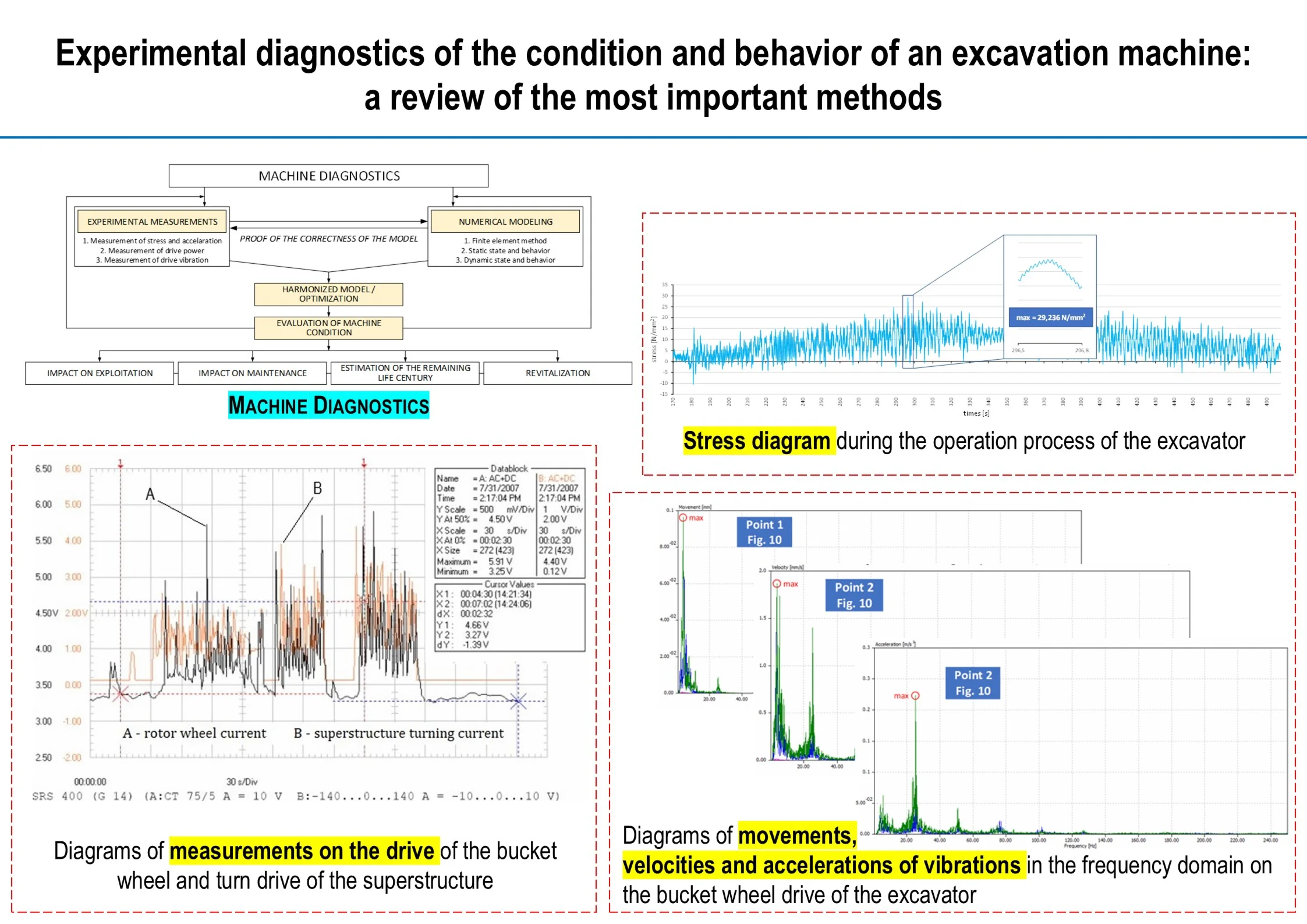
Highlights
- In situ measurements are carried out due to the reconstruction, and modernization of excavation machines.
- Experimental identification of exploitation behavior measurements has a diagnostic character.
- The experiment defines the state and behavior of the steel structure and drive units.
1. Introduction
Excavating machines have a very complex structure with typical peculiarities of static and dynamic behavior. Such a complex structure has two groups of state and behavior observations. These are supporting steel structures and power units for the movement of certain substructures. According to this division, the identification of exploitative behavior is also defined.
By far the largest excavation machine is the bucket wheel excavator. In this paper, the identification of exploitative behavior is taken as an example of application. It can be viewed from two aspects. The first one presents a finite-element analysis done through numerical modeling, which is a diagnostic tool for determining the state and behavior of the load-bearing steel structure. The second aspect is the experimental measurement of acceleration at characteristic points of the structure, measurement of drive loads depending on digging resistance, and measurement of vibration levels on the drive groups of the bucket wheel excavator. In this paper, attention is focused on experimental measurements. Numerical analysis without experimental validation is not reliable enough. That is why the experimental part is important. High-quality measurements indicate the correctness of numerical modeling, especially after reconstruction or revitalization activities. We prove the correctness of the numerical model by experiment. The paper provides an overview of the conducted experimental measurements: measurement of stress and acceleration, measurement of drive load, and measurement of drive vibrations. In addition to the control of the numerical model, the mentioned measurement procedures are used within the framework of the reconstruction, revitalization, and modernization of excavation machines.
Papers from several fields are important for a closer understanding of the idea of this paper. The first area is the numerical examination of the dynamics of the structures of individual assemblies, i.e. the diagnostic aspect of the finite element analysis of the steel construction of excavation machines. In the paper [1], Rusinski and others defined the role of experimental and numerical analyzes in the process of designing and testing dynamically loaded structures. To improve and refine the model, it is necessary to carry out experimental research as proof of the correctness of the model. In their paper [2], Peng et al. performed a simulation of a numerical model by measuring the displacement and pressure variations of hydraulic cylinders in an excavator under shock loads. They considered the measured values of stress and displacement and performed a dynamic simulation of the excavator. Yu et al., in their paper [3], performed an analysis of the mechanical behavior and optimization of the excavator structure using FEM. Numerical analysis showed that in this case the structure of the excavator can be effectively improved. Gnjatović and others in their work [4] defined a new idea regarding the preservation of the excavator structure using the implementation of a frequency-regulated drive of the rotor wheel. The finite element method was used to model the superstructure of the excavator, and its dynamic response was obtained. In their paper [5], Pietrusiak et al. presented a special method for exciting a bucket wheel excavator using modal testing. The method of finite elements and vibration was used. Using this approach, the SchRs4600 bucket wheel excavator was modernized to extend the life of the machine. The advantage of these works [1-5] is in the excellent numerical modeling of the structure and the definition of static and dynamic behavior in response to the excitation force. Numerical modeling was used as a diagnostic method with only one type of experiment as proof of the correctness of the modeling. Whether looking at only local problems or a global analysis of the complete structure, generally the evidence of the measured stress state supported the finite element numerical method. The problems of the complete machine from the aspect of revitalization, modernization and reconstruction were not considered, that is, the problems were not systematically solved by using several experimental measurements at the same time.
Another area is the experimental in situ measurement of stress and acceleration on the steel construction of excavation machines. Bošnjak et al., in their work [6], defined the numerical-experimental path for the reconstruction of the excavator SchRs630 through the following: diagnosing the cause of the occurrence of cracks; defining the mantle reconstruction project; verification of the reconstructed structure by numerical-experimental analysis. Identification of the stress-deformation state of the mantle was carried out using the finite element method. In their work [7], Arsić et al. used a numerical-experimental approach to prove that the safety of the body structure of the rotor excavator structure against fatigue was insufficient during the welding process. The finite element method and stress measurement in the structure as well as the method of central drilling in the structure were used. In their paper [8], Pietrusiak et al. investigated the relationship between stacker-reclaimer superstructure vibrations and harmonic changes of the substructure. The harmonic nature of the change of these loads is derived from the global vibrations of the superstructure that cause the dynamic application of the position of the center of mass. Tian et al. [9] presented a new approach to stress measurement in steel structures. The laser ultrasound technique was used, and the relationship between the speed of the ultrasound wave and the stress was investigated. The results showed that there is a linear dependence between them. Xian et al. [10] defined research that represents a comprehensive approach that integrates dynamics modeling, finite element analysis, and fatigue life prediction of materials using MATLAB. The main results identify areas of stress concentration and fatigue-prone parts, providing insight into design optimization and durability improvement. Within this group of works [6-10], tests of the stress state and acceleration of the structure were performed with results that confirmed the correctness of the model. The measuring points where the voltage state was measured are well-defined. Individual measurements and accelerations were performed for dynamic response, which is important for the global behavior of the structure. However, no measurement was carried out with several experimental methods at the same time, where the importance of the equipment requires such an approach. This comes to the fore when such excavators expect revitalization procedures.
The third area is the experimental in situ measurement of the load on the drive of the excavation machines. In their work [11], Miletić and others determined the dependence of how the wear of the cutting elements affects the operation of the excavator’s rotor wheel drive. By experimentally measuring specific energy consumption and vibrations, the relationship between wear and optimal operation of the drive was established. An artificial neural network combined with fuzzy logic inference (ANFIS) was used to predict critical experimental values. In the paper [12], Miletić et al. established the dependence between the measured energy consumption and the measured amplitude of the vibration speed, in the working technological process. The work resulted in a recommendation for optimal use of the current vibration standard. Lieberman and others in their work [13] dealt with the problem of reducing the power of the excavator drive. They considered options for reducing the power of the excavator and increasing productivity by creating an optimal working element of the original design with a non-uniform arrangement of buckets. Brînaș et al. proposed in [14] a method for calculating the drive power of a bucket wheel excavator by modeling. The proposed method allows us to estimate the load of the rotor wheel motor considering only the specific energy necessary for digging, the volume of excavated material and the time required for digging. The goal is to optimize the drive power of the rotor wheel and thus improve energy efficiency, increase excavator performance and reduce operating costs. Khedkar et al., in their work [15], performed an optimization between the power of the drive, i.e. the required digging force and the design of the bucket. This paper focuses on the method of estimating the digging capacity and forces, as well as the resisting forces generated by rigid soil. The advantages of these works [11-15] are that they directly measured the diagnostic parameters of the drive in a precise and correct way. However, troubleshooting was limited to solving local drive problems. By using certain mathematical methods, an analysis of drive optimization was performed. However, it was an inadequate and simplistic approach to solving the problem from a global point of view. If we look at a large digging machine, this approach is insufficient from the aspect of revitalization and monitoring.
The fourth area is the experimental in situ measurement of vibrations of the drives of excavation machines. In the paper [16] Damnjanović et al presented the results of vibration measurements on the drive of a belt conveyor on a bucket wheel excavator. Movement, speed and acceleration of oscillations were plotted using measured data and the effect of the rear connection of the electromotor mount support on its proper performance was determined. In the paper [17], Karpenko et al. described in detail the identification of faults and the prediction of the state of the machine based on the vibration signal, which is an effective diagnostic tool. In his work [18], Gottvald presented the measurement of vibrations on the SchRs1320 bucket wheel excavator during the digging process. The results confirmed changes in the vibrations of the excavator superstructure during the digging process. In their paper [19], Stefaniak et al presented the problem of automatic diagnostics of mining machine components. The problems cited are data collection and validation and identification of the machine's operating mode. Adequately processed signals are the basis for automatically determining the correct decision thresholds. In their paper [20], Bortnowski et al. provided the detection of roller damage based on the transverse vibration signal measured on the conveyor belt. The correctness of the technical assumptions was checked, and the LSTM neural network algorithm was proposed for the automatic detection of signal anomalies. The adopted detection algorithm has proven itself in both laboratory and in-situ tests. In their paper [21], Hailong and Wei studied the vibration signal of a planetary gear with amplitude, frequency and phase modulation. The proposed mathematical model was used to investigate the modulation behavior of the planetary gear. Amplitude, frequency and phase modulation studies are extremely important for noise and vibration reduction, especially for planetary gear fault diagnosis. Ghazali et al. [22] provided a systematic review of the latest vibration analysis for machine monitoring and diagnosis. Machine vibration signals contain important information regarding the state of the machine such as the source of the fault and its severity. Analysis includes data collection (analyzer and sensors), feature extraction and error recognition techniques using artificial intelligence. The presence of various sensors and communication devices in new smart machines will present a huge new challenge in monitoring and diagnosing vibrations. Within this group of works [16-22], a comprehensive analysis of vibration measurements on drives was performed for diagnostic testing. By using existing standards, displacement, speed and acceleration are defined at optimally selected measuring points. Monitoring achieves a higher level of monitoring of the state and behavior of the driving equipment. The only drawback of this group of works is that it did not consider the problems (mainly of a local nature) with the revitalization and modernization of digging machines.
The advantage of this paper compared to the previously mentioned works is that it contains in one place the most important methods for the experimental identification of problems on digging machines: measuring the stress state on the structure, measuring the load and power on the drives, measuring vibrations at the characteristic points of the drive groups. Diagnostic observation of corrosion using the ultrasonic method and diagnosing cracks using acoustic emission can be added to these methods. Considering the inevitable processes of revitalization, reconstruction and modernization of digging machines, this comprehensive approach comes to the fore.
2. Experimental identification of the exploitation behavior of a bucket wheel excavator
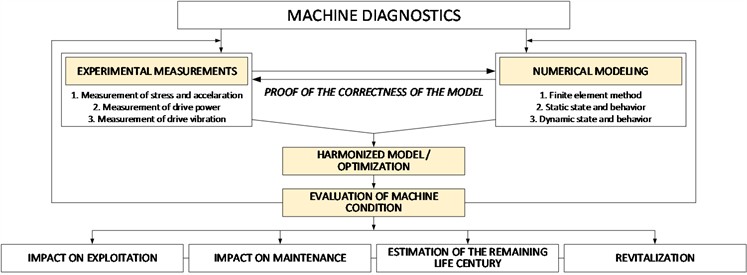
The identification of exploitative behavior depends on the problems encountered in the work. The problems that have arisen with excavators in operation primarily stem from insufficiently well-designed structure geometry, insufficient material resistance, inadequate close relationship between excitation and frequency response of elements, which may have greater or lesser stiffness, etc. A frequent case is the occurrence of all these factors. In his paper [23], Gottvald presented the experimental measurement of the eigen frequencies of the SchRs1320 bucket wheel excavator. He performed a comparison of the results obtained by experimental measurements and detailed numerical simulation. In experimental research, it is worth using the frequency response analysis method already at the stage of designing the material and structure of the machine (or device). This is an effective method for determining the characteristics of structural materials, and particularly their elastic-dissipative properties. Karpenko et al described this method concerning materials with non-linear characteristics in the paper [24]. The finite element method enables the modeling and calculation of complex constructions and problems, and real images of displacements and stresses are determined. Then the actual behavior of the structure is found and a reliable forecast of the response of the structure in operation is given – the causes of bad behavior or yielding of the structure, the estimation of the operational life, and the time of reliable operation of the structure are determined. Numerical modeling is also an excellent diagnostic tool for determining the condition and behavior of a certain structure. An analysis of the structure of the bucket wheel excavator should provide an answer as to whether the existing structure is well designed. If the construction during the exploitation process shows a loosening of the structure, further steps in the diagnosis and reconstruction of the bucket wheel excavator can be considered. The proof of correctness of the developed numerical model is represented by the performed experimental measurements. Fig. 1 shows a diagram showing the position of experimental measurements in the function of machine diagnostics, that is, proof of the correctness of the numerical model.
Experimental measurements are performed to prove the correctness of the numerical model and to diagnose the condition and behavior of the structure and power units. The performed measurements have an impact on the exploitation of the machine and its maintenance, potential revitalization and reconstruction, but also on the assessment of the remaining service life of the machine. Combining all these measurements in the function of machine evaluation as a common goal, especially their simultaneous use, can be considered as a contribution of this work. With that, the importance of this work is also raised during the systematic observation of multi-decade use of the machine, of which there is an exceptional number in the industry.
Fig. 1Machine diagnostics
2.1. Measurement of stress and acceleration
Measurement of stress and acceleration confirms correct numerical modelling, in addition to being a diagnostic tool. The steel structure has the greatest influence on the life of the excavator. It is understood that the criteria consider the standard DIN 22261, which refers to large mining machines. By correctly selecting critical points, as well as with a limited number of measuring points, certain results and knowledge about the steel structure of the excavator can be obtained. Depending on the construction and nature of the load, the method of measuring material stress using strain gauges was chosen [9, 18]. DIN 22261-2 provides the basis for the assessment of measurement results and measurement points. Fig. 2 shows examples of measuring points on SRs400.14/1 and SRs470.20/3 excavators (manufactured by Takraf, Germany).
Fig. 2Locations of stress measurement points

a) Bucket wheel excavator SRs400 – measuring point inner side of the central pillar of the superstructure
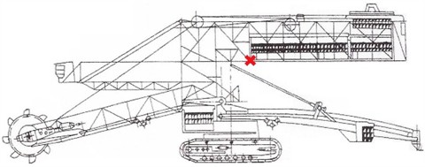
b) Bucket wheel excavator SRs470 – measuring point of the lower support of the counterweight structure
The measurement was carried out during the digging process of the excavator, where the obtained signals are related to the technological conditions of the excavator's operation (height of the cut, thickness of the cut, width of the cut, and position of the boom). The first signal was obtained during the digging process with a change of cut and the appearance of an excavator for the thickness of the cut. The second signal was obtained during the process of transporting the excavator (in the technological process of excavation). Fig. 3 and Fig. 4 show diagrams of force (stress) increments for given measurement locations, which depict the state of stress in the supporting structure of both excavators.
The measurement defines the actual stress in the structure for the given technological operations. The resulting stress must be lower than the maximum allowable stress in the structure, considering the limit of elasticity or Hooke’s law. This approach affects the determination of the remaining life of the excavator structure. Therefore, the limitation is related to the elastic limit of the EN S235 JR or DIN RST 37-2 steel structure (elastic limit is 235 N/mm2) [25].
Fig. 3Stress diagram during the operation process of the SRs400 excavator

a) Excavation process in the block with a change of cut

b) The process of transporting an excavator, without excavation, with the rotation of the bucket wheel
The highest stress increase was recorded at the central column of the upper construction of the SRs400 excavator at 93.77 N/mm2 during the process of the excavator's arrival (transportation) for the thickness of the cut. As can be seen from the diagram, by turning the superstructure to the left, the stress in the central column increases, while when turning to the right, the stress decreases. Knowing that the excavator did not have adequate technological working conditions for maximum work performance, it can be concluded that the increase in stress at the place of the central column is relatively high (still within the limits of the permitted). This means that for a much higher load and impacts during the digging process, which there were and will be during the exploitation process, the stress in the construction will be much higher. Conclusion of the behavior of the supporting steel structure of the bucket wheel excavator SRs400 based on these measurements: the increase in stress adversely affects the fatigue of the structure, which is manifested by the appearance of cracks on the parts of the structure above the measuring point itself. In the case of the SRs470 excavator, the highest stress increase was recorded at the place of the lower support of the counterweight structure of 29.236 N/mm2. The excavator worked in a high block with a cutting height of 4 m, so it can be concluded that the received signals are representative. The lower support is exposed to a greater load, that is, the oscillations of the counterweight structure during the digging process of the excavator to the left have a greater influence on it. The two different design versions of the excavator also define different stress increments. Fig. 5 shows the dependence diagrams of the stress in the construction and the frequency for the given measuring points. Low frequencies up to 2 Hz are expressed.
Fig. 4Stress diagram during the operation process of the SRs470 excavator

a) Excavation process in the block with a change of cut

b) The process of transporting an excavator, without excavation, with the rotation of the bucket wheel
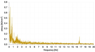
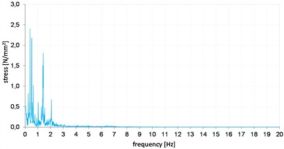
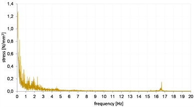
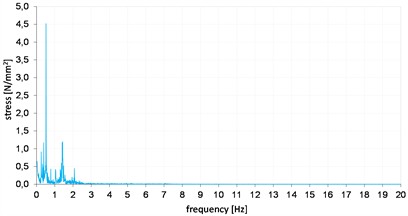
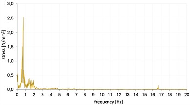
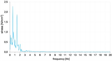
Fig. 5 contains six amplitude-frequency spectra. Acceleration measurements were made on the central pillar of the SRs400 excavator and the counterweight support of the SRs470 excavator. Signals were obtained for three cases with both excavators: during the excavation process to the left and to the right, as well as during the transportation process. In the case of the central pillar of the SRs400 excavator, the measurement was made in the vertical direction of the greatest load (in the direction of the main stress), up-down direction. In the case of the SRs470 excavator counterweight support, the measurement was made in the horizontal direction of the greatest load, left-right direction.
Fig. 5Stress diagram during the excavator digging process, in the frequency domain
a) SRs400: right digging process
d) SRs470: right digging process
b) SRs400: left digging process
e) SRs470: left digging process
c) SRs400: excavator transport
f) SRs470: excavator transport
Globally, the biggest impact on construction should be the digging process itself. The excitation frequency of the structure caused by the digging process of the excavator is calculated based on Eq. (1):
where – number of buckets (for SRs400 it is 12 buckets, and for SRs470 it is 8 buckets); – number of revolutions of the electric motor (for SRs400 it is 1475 min-1, and for SRs470 it is 985 min-1); – transmission ratio of the gearbox (for SRs400 it is 210.7, and for SRs470 it is 128).
This frequency for both excavators is not dominant in the part of the structure where the measurement was made. The values for the SRs400 and SRs470 excavators are 1.4 Hz and 1 Hz, respectively.
The excavator did not have adequate technological conditions, so we should expect an increase in the influence of this frequency on the stress state in the construction of the central pillar when the excavator works in a height block of 5 m and more. In all diagrams during the digging process of the SRs400 excavator, the dominant frequency is 0.78 Hz. It and other pronounced low frequencies originate from elements that have sufficiently large energy of motion at a given frequency to cause stress in the construction. A frequency of 16.7 Hz was also obtained, i.e. the excitation frequency from the conveyor drive on the working wheel arrow strips and the unloading conveyor. Its amplitudes, i.e. stress for the excavation process range from 0.7 N/mm2 to 1.3 N/mm2, i.e. for the transport process 2.5 N/mm2 for the central pillar. In addition to the digging frequency of 1 Hz of the SRs470 excavator, there is also a signal that represents the second harmonic of the digging process, that is, which occurs at 2 Hz. On the lower support, the dominant frequency is 0.522 Hz with an amplitude of 2.14 N/mm2. It and other pronounced low frequencies also originate from elements that have a sufficiently large movement energy at a given frequency to cause the appearance of stress in the structure-oscillation of the entire superstructure in relation to the movement axis, movement of the impeller in the horizontal plane, movement of the entire drive group of the impeller at the place of the rear support or when turning the upper construction of the excavator (problem of the slewing bearing, toothing problem of the drive pinion gear). These are elements that require special supervision and the application of diagnostic methods. Due to the mentioned parameters and values, the best combination is to compare the numerical model and the obtained dynamic behavior (the first few frequency modes of the structure's behavior) with the experimentally obtained data.
2.2. Drive load measurement
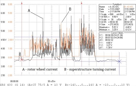
Load measurement is carried out on the following drives: bucket wheel drive, superstructure turn drive, and belt conveyor drives. The load measurement of the bucket wheel drive and the turn of the superstructure take place simultaneously. This is in function of the digging process, i.e. determining the specific resistance to digging, but also the actual power used during the process. Electric motors for driving the working wheel are exposed to a variable load during operation, which varies from idle load to maximum (peak) loads. This variability requires a special mode of measuring the power consumed in the digging process, and that special mode is a continuous measurement using a voltage and current meter with associated software. The device registers the voltage, that is, the current, with which we calculate the total power consumed in the digging process, that is, the active power. Through effective power, we get engaged power. The device simultaneously measured the motor for driving the working wheel and the motor for driving the turn of the superstructure. Fig. 5 shows measurement diagrams on the drive of the bucket wheel and the drive of the circular movement of the SRs400 excavator superstructure. Using the obtained parameters, the specific resistance of the material to digging is calculated. The mean instantaneous current drawn by the drive from the network represents the mean value of the maximum and minimum current peaks that are read from the electronic data recorder (Fig. 6). Fig. 5 shows the voltage value, which on the resulting diagram has a proportion of the output to the current, 10 V corresponds to 75 A for the drive of the rotor wheel, and 10 V corresponds to 140 A for the drive of the upper construction of the excavator. By finding the value of the voltage/current peaks in Fig. 6, the specific digging resistance is defined according to the given Eqs. (2-7).
The effective current is determined according to Eq. (2):
where is the peak current (the maximum current).
The power required for the excavation process is calculated based on Eq. (3):
where, – power consumed in the digging process, kW; – nominal voltage, V; – engine power factor.
The power delivered to the motor to drive the bucket wheel is calculated based on Eq. (4):
where – efficiency coefficient of the drive.
The power spent on the digging process represents the difference between the delivered power and the power required to raise the material to the discharge height. It is given in the Eq. (5):
The force required to excavate the material is calculated based on the digging power and the peripheral speed of the bucket wheel. It is given in the Eq. (6):
where is the peripheral speed of the bucket wheel, m/s.
The ratio of the power spent on the digging process and the total length of the cutting edges in contact with the material , the specific resistance of the material to digging is calculated by the length of the cutting edges. It is given in the Eq. (7):
Specific energy consumption is calculated according to Eq. (8):
where – delivered engine power for driving the rotor wheel, kW; – idling power of the engine for driving the rotor wheel, kW; – realized capacity of the rotary excavator at a given moment, m3/h.
Fig. 6, which was obtained directly from the oscilloscope, shows measurement diagrams on the drive of the rotor wheel and on the slewing drive of the SRs400 excavator superstructure.
Fig. 6Diagrams of measurements on the drive of the bucket wheel and turn drive of the superstructure – excavator SRs400
In addition, to load measuring devices, instruments on the excavator were also used, which are in function of the microtechnological parameters of the block, i.e. the determination of the following parameters, and with the help of which the specific resistance of the material to digging is reached: speed of the circular movement of the excavator (turn of the superstructure), the appearance of the excavator (thickness of the cut), the height position of the working wheel and the angular position of the arrow of the working wheel (measured from the longitudinal axis of the excavator).
For the measurement on the bucket wheel, the following parameters arrived at, based on Fig. 6:
1) Maximum digging resistance: 620 N/cm.
2) The mean maximum resistance to digging is in the range 520 – 620 N/cm.
3) Specific cutting force developed on the bucket: 910 N/cm.
For the given working conditions, the specific resistance to digging moves within limits that did not present a problem during digging, from the aspect of the specific cutting force of the excavator. The specific energy consumption is relatively high for the performance of the bucket wheel and drive of the SRs400 excavator. It ranges from 0.17 to 0.23 kWh/m3 (average values). Based on this, it is possible to determine bad geometry, the position, and number of cutting elements (teeth) on the bucket, but also the geometry of the bucket itself. The superstructure turn drive had relatively small values and no pronounced peaks. This was not expected, knowing that during this measurement the excavator had a turning speed of the superstructure of 18 m/min, which is about 55 % of the maximum value.
Fig. 7 shows voltage and current measurement diagrams on the drive of the bucket wheel and on the drive of the circular motion of the upper construction of the SRs470 excavator.
Fig. 7Diagrams of measurements on the drive of the bucket wheel and turn drive of the superstructure – excavator SRs470
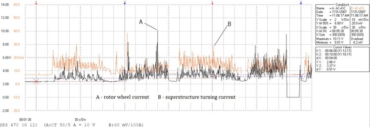
For measurement on the working wheel of the SRs470 excavator, the following parameters were obtained:
1) Maximum digging resistance, peak value - peak: 1108 N/cm – the appearance of hitting stone and hard clay.
2) The mean maximum resistance to digging is in the range of 280-750 N/cm.
3) Specific cutting force developed on the bucket: 600 N/cm.
Such values of parameters of resistance to digging and the occurrence of shocks in the system hurt all elements of digging and torque transmission. The specific energy consumption is relatively high for the performance of the SRs470 excavator impeller and drive. It ranges from 0.11 to 0.20 kWh/m3 (average values). Based on this, it is possible to determine bad geometry, the position, and number of cutting elements (teeth) on the bucket, but also the geometry of the bucket itself.
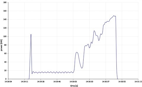
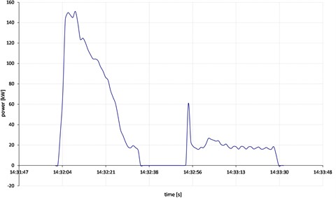
Measuring the load of the conveyor drive on the excavator is a function of the process of determining the actual power used in the process of transporting materials that is, energy consumption. Measurements were made for three different working cases: measurement under working load – band conveyor is full of material, measurement under load – belt empty, and measurement when the belt is full. Fig. 8 shows power measurement diagrams on the drive of the conveyor belt of the rotor wheel boom of the SRs400 excavator.
Fig. 8Diagrams of power measurement on the drive of the belt conveyor of the rotor wheel of the excavator SRs400
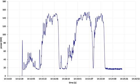
a) Diagram of the actual power of the conveyor drive during operation when the belt is full
b) Diagram of the actual power of the conveyor drive during operation when the belt is empty
c) Current diagram of the conveyor drive when the full belt is started from the stand
Consumed power (installed engine power is 160 kW):
‒ starting the empty conveyor: max 105 kW.
‒ power value during operation when the material is on the conveyor – the belt is full: max 160 kW.
‒ nominal power value during operation when the conveyor is empty: max 140-150 kW.
‒ starting the conveyor under load - the belt is full: max 150-160 kW.
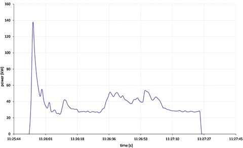
Fig. 9 shows power measurement diagrams on the drive of the conveyor belt of the rotor wheel boom of the SRs470 excavator.
Fig. 9Diagrams of power measurement on the drive of the belt conveyor of the rotor wheel of the excavator SRs470
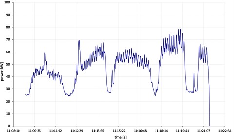
a) Diagram of the actual power of the conveyor drive during operation when the belt is full
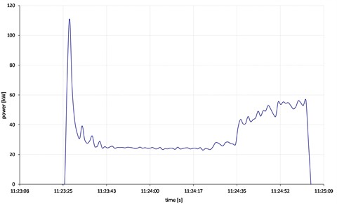
b) Diagram of the actual power of the conveyor drive during operation when the belt is empty
c) Current diagram of the conveyor drive when the full belt is started from the stand
Table 1 shows the power values of the electric motor at different work processes for the belt conveyor of the rotor wheel boom, for the SRs400 and SRs470 excavators.
Table 1Electric motor power values
Excavator SRs400 | Excavator SRs470 | |
Installed engine power | 160 kW | 132 kW |
Engine power when starting the belt without load | max 105 kW | max 110 kW |
Engine power in operation when the belt is full | max 155 kW | max 80 kW |
Engine power in operation when the belt is empty | max 150 kW | max 60 kW |
Engine power when starting the belt under load | max 150 kW | max 140 kW |
Modern control and monitoring systems enable diagnostics of all system elements from the control center. With the application of an electrical drive with a controlled material transport speed, the energy efficiency of the plant increases and leads to the reduction of instantaneous active power. In combination with the appropriate control system and diagnostic tools, it is possible to create an efficient conveyor belt system, where there is no problem of unequal load distribution.
2.3. Measurement of drive vibrations
Vibrations are caused by an excitation force that can be an external force or a force generated in the machine itself. The mode of vibration is completely determined by the excitation force and its frequency, so vibration analysis can be used to determine the state of the machine, i.e. for diagnosing her work, that is, the identification of faults and the prediction of the state of the machine. Vibration also represents a motion that results in a restitution force. If several excitation forces are acting simultaneously (or periodically) at different frequencies, the resulting vibration graphic is highly intricate and difficult to interpret [26]. However, regardless of the case, to understand the complex vibrations of a bucket wheel excavator, one must begin with linear harmonics, the basic parameters of which are: elongation (displacement) , amplitude , linear frequency , natural (circular) frequency , period , velocity and acceleration . The correlations between these parameters are well known.
Given that:
vibration velocity is proportional to frequency since:
and acceleration is proportional to the square of frequency because [26]:
This means that a large displacement and high frequency result in high velocity and extremely high acceleration. The vibration amplitude depends on two factors: the amplitude of the excitation force and the dynamic stiffness of the mechanical system , or:
The dynamic stiffness of a mechanical system is determined by a set of characteristics such as stiffness:
where are its mass and damping , with which the bucket wheel excavator counteracts the external force [26].
This means that the oscillation amplitude can increase if the intensity of the excitation force increases or if the dynamic stiffness decreases, or it can decrease if the intensity of the excitation force decreases or the dynamic stiffness increases [26].
Many dynamic systems are extremely complicated when it comes to vibrations because there are many vibration sources on them. A dynamic system such as a bucket wheel excavator is not infinitely rigid because it has different degrees of flexibility at different frequencies. Its vibration is a reaction to an external force and depends on the nature of the excitation force and the dynamic characteristics of the mechanical structure. Each rotating part, as well as each moving part on the excavator, is the cause of its low-frequency vibrations. When the excavator is in the excavation process, these own low-frequency vibrations should be added to the vibrations caused by external dynamic loads, which also have many sources. The most unfavorable state for a construction is the resonant state, i.e. when there is a match between its low-frequency vibrations and vibrations caused by external dynamic loads. Vibration measurements were performed at characteristic points of the power units: support of the torque lever on the structure, both engine mounts and input and output of the gearbox mount. Vibration measurements were made at characteristic points of the drive group of the SRs1200 bucket wheel drive. Those places are given in Fig. 10.
Fig. 10Measuring points on the rotor wheel drive: 1 – support on the structure, 2 – motor housing 1, 3 – motor housing 2, 4 – gearbox input shaft housing, 5 – gearbox output shaft housing
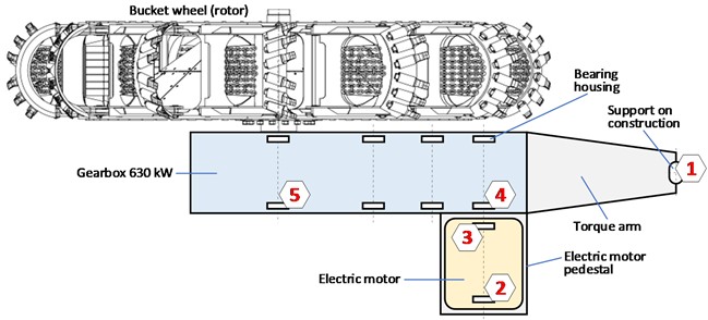
The measurement was made in three directions: vertical, horizontal and axial, during the operation of the excavator under load, in the digging process. Blue colour indicates vibrations in the horizontal direction, green in the vertical direction, and red in the axial direction. Fig. 11 shows the vibration diagrams at the characteristic points of the bucket wheel drive of the SRs1200 excavator in the frequency domain (measured values of movement, speed and acceleration).
By measuring the vibrations on the bucket wheel drive on the excavator, the following dominant frequencies were found:
1) The frequency of 25 Hz originates from the excitation (the number of revolutions of the electric motor is 1500 min-1) and the signal was recorded at all 5 measurement points; the acceleration amplitude ranged from 0.07 to 0.25 m/s2 (all excitation frequencies are expressed in two directions, in vertical and horizontal); the highest value was recorded on electric motor housing 1; the obtained values are not alarming from the aspect of operational safety, but they may indicate problems; excitation harmonics at 50 and 75 Hz are also expressed; the velocity amplitude ranged from 0.5 to 1.4 mm/s; the highest value was recorded on electric motor housing 1; at this location, we should expect a problem with the bearing in the future (monitoring and adequately maintenance); based on the ISO 20816-3:2022 standard, for this type of drive, the values are within the permitted limits [27]; the excitation frequency will always exist, but depending on the state of the system, on the relaxation of the stiffness level, this signal may have an increasing trend.
2) Low frequencies up to 5 Hz are present at all measurement points; their acceleration amplitude ranges from 0.02 to 0.05 m/s2 (vertical and horizontal direction); the velocity amplitude ranges from 0.9 to 1.9 mm/s; these low frequencies are most often associated with the rear support on the boom construction of the excavator; they may be the result of a bad connection condition; based on the parameters of the same standard ISO 20816-3:2022, the values are within the permitted limits [27].
Fig. 11Diagrams of movements, velocities and accelerations of vibrations in the frequency domain on the bucket wheel drive of the SRs1200 excavator
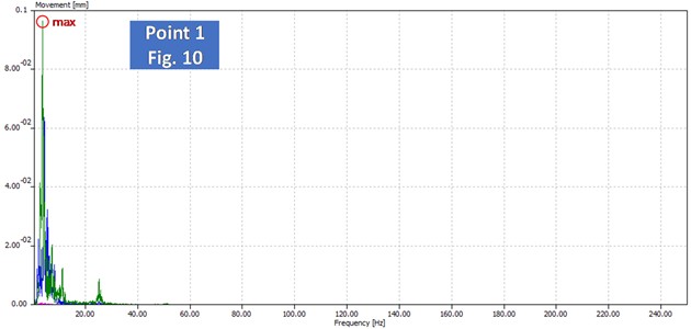
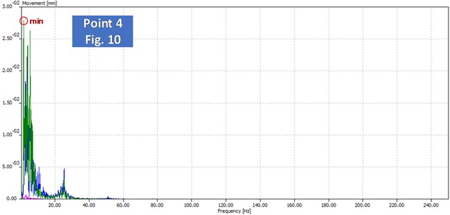
a) Movement diagrams in the frequency domain (maximum and minimum)
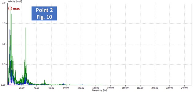
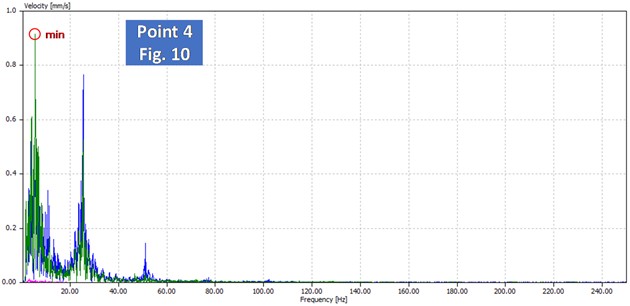
b) Velocity diagrams in the frequency domain (maximum and minimum)
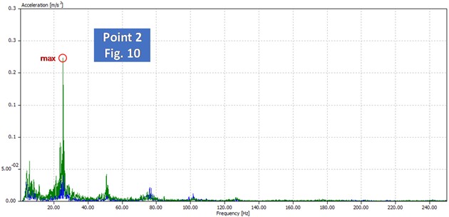
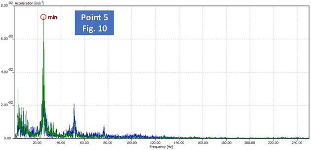
c) Acceleration diagrams in the frequency domain (maximum and minimum)
3. Discussion
The measurement of the stress state and acceleration was performed on two bucket wheel excavators using the method of measuring material stress using measuring tapes. The assessment of the results of the measurement of the stress state and the measuring point on the supporting structure was performed based on the standard DIN 22261-2. The measurement was carried out in the loaded state of the excavator, i.e. the signals were obtained during the process of effective digging and the transport process in the technological process of excavation of the excavator. The recommendation for such measurements would be to carry out the first (initial) measurement while the excavator is still in the assembly process (in some cases, parts of the structure and in the pre-assembly process), at the same pre-determined points. This would affect the quality of the corresponding data in the time domain: about the fatigue of materials, service life, static and dynamic conditions, and behavior of the excavator. The highest stress on the SRs400 excavator is at the place of the central pillar of the upper structure of the excavator and is 93.77 N/mm2, and this is during the process of the excavator's arrival (transportation) for the thickness of the cut. As the thickness of the cut increases, so does the internal stress in the structure. If the technological conditions were adequate, the increase in stress would be even higher. In any case, the stress increment is within the permissible limits for the given structural steel and the given measurement conditions. When working the excavator in an adequate block (maximum height and width of the block with the permitted thickness of the cut), the digging/excitation frequency of 1.4 Hz would be even more pronounced (the amplitude would be higher). Overlapping this value with the own frequency of the excavator superstructure structure (with the first or second harmonic) would lead to a weakening of the supporting steel structure. The highest stress in the SRs470 excavator is at the place of the lower support of the counterweight structure and is 29.2 N/mm2. The lower support has a greater load when the thickness of the cut increases. When operating the SRs470 excavator in the block, the digging/excitation frequency of 1 Hz is more pronounced as is its second harmonic at 2 Hz (the amplitude would be greater). Low expressed frequencies originate from elements that have sufficiently large energy of motion at a given frequency to cause stress in the structure and its yielding. The limitation of the technological parameters of the excavator operation according to the achieved internal stress has the following relationship: if the obtained stress in the work process is about 50 % of the permitted stress for that structural steel, it represents the limit for the cutting parameters (height, thickness, width). In this way, the correct way of the exploitation process is affected. By respecting the basic premises of Hooke's law for a given structural steel, the optimization of the excavator's operating parameters can be managed. If material fatigue were assumed, engineering post-design could influence the design of the structure, supports, and loading.
The bucket wheel excavator has several drive groups important for measuring load, engaged power, and specific resistance: bucket wheel drive, superstructure turn drive, and belt conveyor drives. The measured maximum digging resistance value of the SRs400 excavator is 620 N/cm, while the specific cutting force is 910 N/cm. The excavator did not have an adequate cut, so the measured values are well below the cutting force caused by the bucket wheel drive. Nevertheless, the specific energy consumption is in the range of 0.17-0.23 kWh/m3, which represents relatively high values and indicates problems with the geometry of the cutting elements and the bucket. The measured maximum value of the digging resistance of the SRs470 excavator is 1108 N/cm, while the specific cutting force is 900 N/cm. Such a maximum value was caused by the buckets encountering extremely hard clay and stone singles. Specific energy consumption is relatively high and is in the range of 0.11-0.20 kWh/m3 (bad geometry and number of cutting elements/teeth on the bucket). The obtained parameters indicate a change in the following parameters: changing the geometry and number of cutting elements on the buckets and increasing the power and torque of the drive by 20 %. The nominal value of the specific electricity consumption must be less than 0.10 kWh/m3.
Vibrations represent the best diagnostic tool for defining the condition and behavior of power units. The resulting diagrams were analysed in the frequency domain, by measuring the speed and acceleration of vibrations. An analysis of the vibration level of the bucket-wheel drive gearbox was performed. For further expertise of the obtained results, the ISO 20816-3:2022 standard is used, which defines values from the aspect of permissible vibration and alarm conditions (vibration measurement of industrial machines with power above 15 kW and speed range 120 rpm – 15000 rpm). The operation of the drive under load multiplies the dynamic response, so to assess the state of the drive, it is taken when it is under load (sufficiently heated drive). The influence of different vibration sources can be very large. First, these are the cutting elements, their wear and tear and their position on the bucket. An adequate standard defines the amplitude value of vibration speeds as an indicator of the current state of the drive. In the case of acceleration, a characteristic peak at a certain frequency indicates the location of a potential problem, and the amplitude indicates the strength of the problem, i.e. whether to react in each situation. Vibration measurements were made at characteristic points of the electric motor, gearbox and supports. The power of the analysed drive of the bucket wheel of the SRs1200 excavator is above 300 kW, whereby the group of standards is determined (the actual value of the drive is 630 kW). All obtained maximum vibration speed values are in the range of 0.5 mm/s to 1.9 mm/s (for the bucket wheel drive of the SRs1200 excavator). All values are acceptable by default. Accelerations range from 0.02 m/s2 to 0.25 m/s2. These values are low and are considered acceptable for work. A problem that may arise in future work is that the excitation frequency of the electric motor may overlap with the frequency of the supporting construction of the reducer. (½ of the fundamental value or its second harmonic). This can cause either a failure of the bearings of the electric motor and the input pair of the reducer or a crack in the supporting structure (depending on the strength of the system part and the amplitude level).
4. Conclusions
In this paper, the basic procedure for conducting experimental identification of the exploitation behavior of bucket wheel excavators is given. On such complex machines, to define the optimal working life, the bearing steel structure and drive groups are observed. This approach, in addition to dealing with post-design, can also be used as an excellent diagnostic tool for determining the condition and behavior of the load-bearing steel structure. To prove the correctness of this modeling method, experimental measurements are performed: measurement of stress state and acceleration, measurement of load and engaged drive power, and measurement of drive vibrations. From the aspect of experimental identification of the exploitation behavior of bucket wheel excavators, all these measurements have a diagnostic character.
The previous researches were mostly related to individual tests, depending on the current state of the equipment. In other words, only if the structure cracks, the stress state measurements are performed. This paper introduces a systematic investigation aimed at monitoring the condition and behavior of equipment on a bucket-wheel excavator. This approach forms the backbone of predictive maintenance. In addition to the tests performed on the bucket wheel excavator, to round off the entire diagnostic research, corrosion testing can be performed by ultrasonic thickness measurement, as well as crack formation monitoring using acoustic emission transducers. The presented method of observation with the obtained huge amount of data, allows artificial intelligence, i.e. machine learning, to predict anomalies. Based on the data, information is defined that allows engineering to make a correct statement about the operation, maintenance and service life of the excavator.
Conducted measurements of the stress state on the steel structure indicated that the resulting stress was up to 50 % of the permitted stress. By optimizing the technological process of the excavator, it is possible to ensure that the voltage is always within the permitted limits. Specific energy consumption was up to 0.23 kWh/m3, which is a high value. The nominal optimal value of specific energy consumption must be below 0.1 kWh/m3. To achieve this, the geometry of the cutting elements must be optimized and the torque of the drive must be increased. The measured values of vibration speeds and accelerations are acceptable for the given types of drives. In particular, care should be taken to ensure that the frequency of excitation of the electric motor and the digging process does not coincide with the frequency of the supporting structure, gearboxes and its elements. This may cause malfunction and downtime.
Experimental identification of the operational behavior of bucket wheel excavators is carried out to define the condition and behavior of the supporting steel structure and drive units. In this way, the management of the excavator is affected by the aspect of life and correct use. Also, an optimal relationship can be set between the effectiveness of the excavator and the costs incurred during the operation and maintenance process.
References
-
E. Rusinski, J. Czmochowski, and D. Pietrusiak, “Selected problems in designing and constructing surface mining machinery,” FME Transactions, Vol. 40, pp. 153–164, 2012.
-
L. Peng, Z. Chen, Y. Shi, G. Li, and D. Zheng, “Investigation of structural stress monitoring system on excavator under impact loads,” in IOP Conference Series: Earth and Environmental Science, Vol. 719, No. 3, p. 032022, Apr. 2021, https://doi.org/10.1088/1755-1315/719/3/032022
-
C. Yu, Y. Bao, and Q. Li, “Finite element analysis of excavator mechanical behavior and boom structure optimization,” Measurement, Vol. 173, p. 108637, Mar. 2021, https://doi.org/10.1016/j.measurement.2020.108637
-
N. Gnjatović, S. Bošnjak, and A. Stefanović, “Analysis of the dynamic response as a basis for the efficient protection of large structure health using controllable frequency-controlled drives,” Mathematics, Vol. 11, No. 1, p. 154, Dec. 2022, https://doi.org/10.3390/math11010154
-
D. Pietrusiak, P. Moczko, and E. Rusiński, “World’s largest movable mining machine vibration testing-numerical and experimental approach,” in Proceedings of International Conference on Noise and Vibration Engineering (ISMA2016) and International Conference on Uncertainty in Structural Dynamics (USD2016), pp. 2287–2299, 2016.
-
S. Bošnjak, M. Pantelić, N. Zrnić, N. Gnjatović, and M. Đorđević, “Failure analysis and reconstruction design of the slewing platform mantle of the bucket wheel excavator O&K SchRs 630,” Engineering Failure Analysis, Vol. 18, No. 2, pp. 658–669, Mar. 2011, https://doi.org/10.1016/j.engfailanal.2010.09.035
-
M. Arsić, S. Bošnjak, N. Zrnić, A. Sedmak, and N. Gnjatović, “Bucket wheel failure caused by residual stresses in welded joints,” Engineering Failure Analysis, Vol. 18, No. 2, pp. 700–712, Mar. 2011, https://doi.org/10.1016/j.engfailanal.2010.11.009
-
D. Pietrusiak, T. Smolnicki, and M. Stanńco, “The influence of superstructure vibrations on operational loads in the undercarriage of bulk material handling machine,” Archives of Civil and Mechanical Engineering, Vol. 17, No. 4, pp. 855–862, Sep. 2017, https://doi.org/10.1016/j.acme.2017.03.001
-
H. Tian, Y. Kong, B. Liu, B. Ouyang, Z. He, and L. Liao, “Research on the method of absolute stress measurement for steel structures via laser ultrasonic,” Buildings, Vol. 14, No. 3, p. 602, Feb. 2024, https://doi.org/10.3390/buildings14030602
-
C. Xian, H. Zhang, Y.-C. Kim, H. Zhang, and Y. Liu, “Programmed system for fatigue life prediction of excavator turntables based on multi-body dynamics and finite element analysis,” Heliyon, Vol. 10, No. 12, p. e33126, Jun. 2024, https://doi.org/10.1016/j.heliyon.2024.e33126
-
F. Miletić, P. D. Jovančić, M. Milovančević, and D. Ignjatović, “Adaptive neuro-fuzzy prediction of operation of the bucket wheel drive based on wear of cutting elements,” Advances in Engineering Software, Vol. 146, p. 102824, Aug. 2020, https://doi.org/10.1016/j.advengsoft.2020.102824
-
F. M. Miletic, P. D. Jovancic, M. D. Milovancevic, M. L. Tanasijevic, and S. P. Djenadic, “Determining the impact of cutting elements state on the bucket-wheel excavator vibration and energy consumption,” Journal of Vibration Engineering and Technologies, Vol. 10, No. 5, pp. 1765–1777, Apr. 2022, https://doi.org/10.1007/s42417-022-00482-3
-
Y. Liberman and O. Lukashuk, “Power consumption reduction of bucket wheel excavator drives and its productivity increase,” in Lecture Notes in Mechanical Engineering, pp. 869–880, Aug. 2022, https://doi.org/10.1007/978-3-031-14125-6_85
-
I. Brînaș et al., “Determination of the bucket wheel drive power by computer modeling based on specific energy consumption and cutting geometry,” Energies, Vol. 14, No. 13, p. 3892, Jun. 2021, https://doi.org/10.3390/en14133892
-
Y. Khedkar, H. Nagpure, P. Dendage, P. Shinde, S. Naikavade, and T. Dey, “The evaluation of forces acting on excavator bucket and its capacity,” Materials Today: Proceedings, Vol. 68, No. 6, pp. 2591–2596, Jan. 2022, https://doi.org/10.1016/j.matpr.2022.10.013
-
V. Damnjanović, P. Jovančić, and S. Aleksandrović, “Extensive vibrations of the belt conveyor drive electromotor of a bucket wheel excavator as a result of intensified wear-and-tear of its mount support,” Journal of Vibroengineering, Vol. 19, No. 1, pp. 214–222, Feb. 2017, https://doi.org/10.21595/jve.2016.17321
-
M. Karpenko et al., “Performance evaluation of extruded polystyrene foam for aerospace engineering applications using frequency analyses,” The International Journal of Advanced Manufacturing Technology, Vol. 126, No. 11-12, pp. 5515–5526, May 2023, https://doi.org/10.1007/s00170-023-11503-0
-
J. Gottvald, “The calculation and measurement of the natural frequencies of the bucket wheel excavator SchRs 1320/4x30,” Transport, Vol. 25, No. 3, pp. 269–277, Sep. 2010, https://doi.org/10.3846/transport.2010.33
-
P. Stefaniak et al., “Selected problems and challenges of automatic diagnosis of mining machinery components,” (in Polish), CUPRUM – Czasopismo Naukowo-Techniczne Górnictwa Rud, Vol. 3, No. 76, 2015.
-
P. Bortnowski, R. Król, and M. Ozdoba, “Roller damage detection method based on the measurement of transverse vibrations of the conveyor belt,” Eksploatacja i Niezawodność – Maintenance and Reliability, Vol. 24, No. 3, pp. 510–521, Jun. 2022, https://doi.org/10.17531/ein.2022.3.12
-
H. Sun and W. Liu, “Vibration signal analysis of planetary gear with amplitude, frequency and phase modulation,” Noise Control Engineering Journal, Vol. 69, No. 6, pp. 490–499, Nov. 2021, https://doi.org/10.3397/1/376946
-
M. H. Mohd Ghazali and W. Rahiman, “Vibration analysis for machine monitoring and diagnosis: a systematic review,” Shock and Vibration, Vol. 2021, No. 1, Sep. 2021, https://doi.org/10.1155/2021/9469318
-
J. Gottvald, “Analysis of vibrations of bucket wheel excavator SchRs1320 during mining process,” FME Transactions, Vol. 40, pp. 165–170, 2012.
-
M. Karpenko, P. Ževžikov, M. Stosiak, P. Skačkauskas, A. Borucka, and M. Delembovskyi, “Vibration research on centrifugal loop dryer machines used in plastic recycling processes,” Machines, Vol. 12, No. 1, p. 29, Jan. 2024, https://doi.org/10.3390/machines12010029
-
“S235JR | 1.0038.”. https://www.thyssenkrupp-materials-processing-europe.com/en/c-steel/hot-strip/s235jr-s355k2/s235jr
-
V. Damnjanović and P. Jovančić, “Validation of bucket wheel drive component model through vibration monitoring: A torque arm key study,” Journal of Vibroengineering, Vol. 16, No. 3, pp. 1212–1218, 2014.
-
“Mechanical vibration – Measurement and evaluation of machine vibration Part 3: Industrial machinery with a power rating above 15 kW and operating speeds between 120 r/min and 30 000 r/min,” ISO 20816-3:2022, 2022.
About this article
This article is a contribution to project TR035040 funded by the Serbian Ministry of Education and Science.
The datasets generated during and/or analyzed during the current study are available from the corresponding author on reasonable request.
Predrag Jovančić: conceptualization, formal analysis. Snežana Aleksandrović: methodology, formal analysis. Aleksandar Madžarević: methodology, supervision. Filip Miletić: investigation, software. Stevan Djenadić: investigation, software.
The authors declare that they have no conflict of interest.
