Abstract
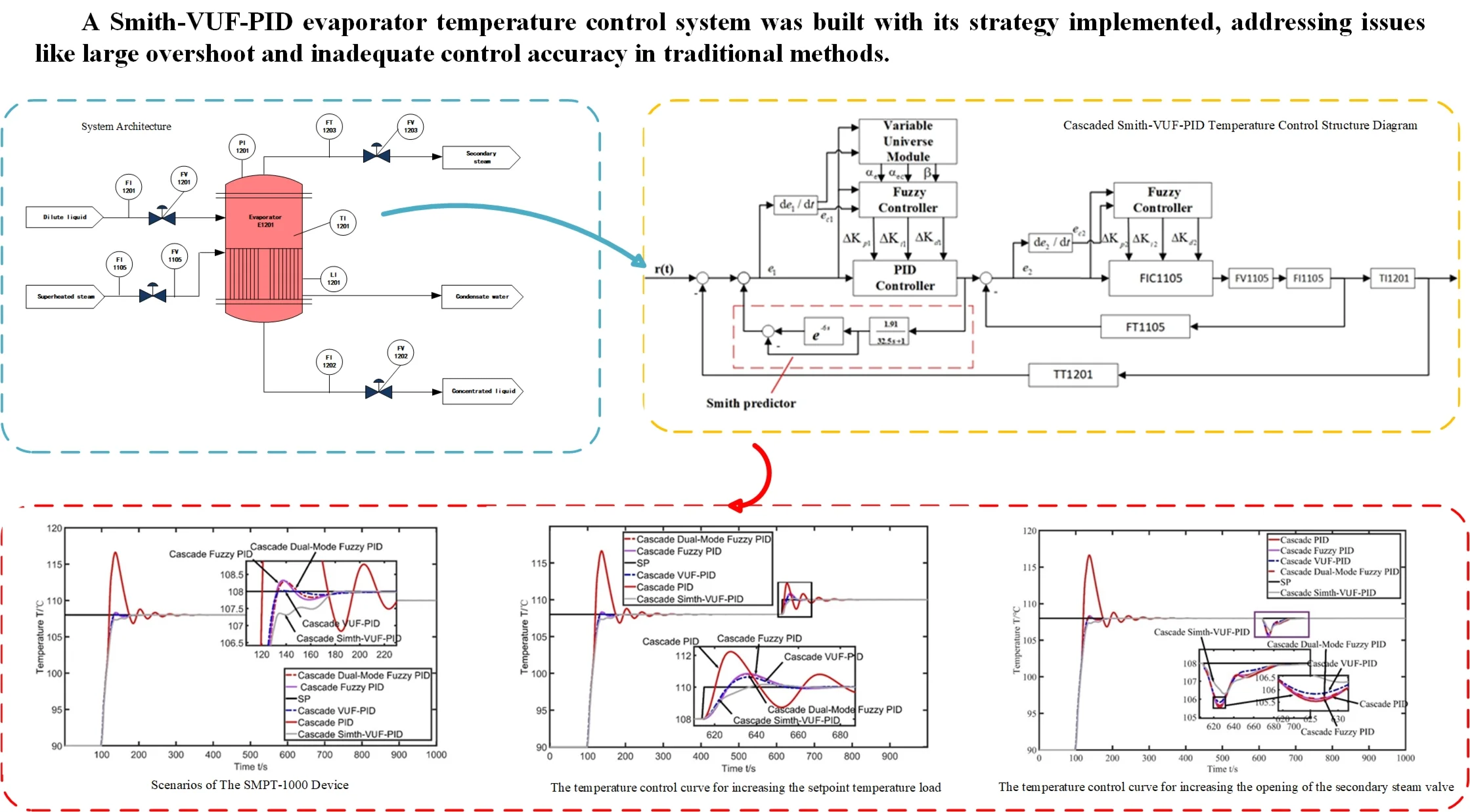
Temperature serves as a critical process parameter in industrial systems, directly influencing reaction kinetics, product quality, and operational efficiency. The variation of temperature can affect reaction rate, product quality, and impurity generation, directly impacting production efficiency and product performance. However, due to the nonlinearity of temperature control systems, traditional controllers cannot meet design requirements, particularly in scenarios demanding high - temperature control accuracy, it is difficult for them to achieve a small deviation range. Therefore, this study focuses on the evaporator as the controlled object and conducts modeling, simulation analysis, and control strategy research on the evaporator temperature control system. It establishes the Smith-variable universe fuzzy PID(Smith-VUF-PID) temperature control system and deploys control strategies, solving issues such as large overshoot and inadequate control accuracy often encountered with traditional methods.
Highlights
- VUF-PID adjusts fuzzy universes via error-derived scaling factors, enhancing adaptability with faster settling, smaller overshoot, and higher accuracy than conventional fuzzy PID.
- Smith-VUF-PID integrates Smith predictor and variable-universe fuzzy PID, greatly reducing pure time delay. It achieves minimal overshoot and shorter settling time, outperforming traditional algorithms.
- Particle swarm optimization optimizes system parameters, achieving a precise model fit better than the tangent method, supporting reliable control implementation.
- Validated on SMPT-1000/PCS7, Smith-VUF-PID shows strong robustness under disturbances with fast recovery, demonstrating practical value.
1. Introduction
As a thermal energy transfer device, the evaporator facilitates phase change from liquid to vapor through controlled heating, mainly used as a container for concentration and purification. The quality of the product and the rate of evaporation in the evaporator are determined by the stable temperature [1]. Therefore, designing a temperature controller with strong adaptive capacity and high control accuracy has been the focus of research in recent years.
PID (Proportional-Integral-Differential) controllers are commonly used in industrial evaporator temperature control systems. However, these controllers cannot respond quickly to disturbances. A combination of fuzzy control and PID control is introduced by analyzing the dynamic and static characteristics of the evaporator temperature control system. The fuzzy controller adjusts the PID parameters in real-time online, thereby improving the system's response speed. Sun Jun compared the results of the double-cascade fuzzy PID control method and the cascade PID control method in the evaporator temperature system. It was found that the fuzzy PID method had higher accuracy [2]. Dang Li utilized the variable universe fuzzy PID technology to achieve the temperature control of the heat treatment process [3]. Wang Yuzhong et al. designed the variable universe fuzzy PID controller, and the lining induction heating system model was used to verify its performance. This research can be used as a reference for induction heating precise control and evidence that the variable universe fuzzy PID control can satisfy the lining induction heating process [4]. Wei Bin proposed the use of a particle swarm optimization algorithm to optimize the PID parameters of the variable universe fuzzy controller, which improved the tracking performance of the control system [5]. Zhu Guiying et al. successfully controlled the mobile workbench system using the variable universe fuzzy PID algorithm, demonstrating its suitability for complex nonlinear coupled control systems [6]. Jiang Wei used the variable universe fuzzy PID vibration control method to achieve better vibration control of building structures [7]. Li Hongqiang proposed a control method that integrates a variable universe fuzzy PID controller with neural network technology. Taken together, the above results show that the combination of variable‐domain fuzzy PID controller and neural network technology in beer production has achieved excellent control results [8]. Jiang Qingfeng achieved good results in controlling the core power of a molten salt reactor using the variable universe fuzzy PID algorithm through simulation experiments [9]. Huang Mengtao solved the synchronization problem between motors in the electronic shaft gravure system using the variable universe fuzzy PID algorithm, proving its better anti-interference and response speed [10]. The variable universe fuzzy PID algorithm was used to solve the stability problem of a three-degree-of-freedom helicopter system, improving the high-precision tracking of the system trajectory [11].
In this paper, the strategy of using the variable universe fuzzy PID control to control the evaporator temperature is adopted. Based on fuzzy control, the idea of a variable domain is introduced. By changing the scaling factors of online tuning, the fuzzy controller's quantization factor and proportional factor are changed, thereby making the input and output domains of the fuzzy controller expand, improving the adaptive capacity and control accuracy of the control system. A variable universe fuzzy PID controller is developed in the Siemens process control system, and simulation experiments are conducted on the SMPT-1000 (Super Multifunction Process Control Training System) equipment. The experimental results show that this method reduces the overshoot, settling time, and other characteristic parameters of the control system, and improves the adaptive capacity and control accuracy of the evaporator temperature control system [12].
The article has the following parts: Part 2 introduces the process flow of the evaporator temperature control system; Part 3 designs the Smith-VUF-PID controller; Part 4 describes the steps implemented on PCS7; Part 5 analyzes the experimental results of the proposed algorithm; Finally, Part 6 presents the conclusions of this article and discusses future work.
2. Process analysis
The basic process principle of this evaporator is to heat the juice with the heat of steam, and the dilute liquid absorbs heat and becomes concentrated juice. The specific process is as follows: Using 5 % concentration juice as raw material, it enters the evaporator E1201 through valve FV1201 by controlling the flow rate of FI1201; Superheated steam with a temperature of 450 ℃ and a flow rate of FI1105 passes through the middle of the evaporator and flows through the jacket of the evaporator through valve FV1105 to heat the dilute liquid; After absorbing heat, the dilute liquid turns into secondary steam and is discharged from the top of the evaporator through valve FV1203 with a flow rate of FI1203; The concentrated liquid with a concentration of AT1201 is discharged from the bottom of the evaporator through valve FV1202 with a flow rate of FT1202 as the finished product [13]. The process flow diagram is shown in Fig. 1.
Fig. 1System architecture chart
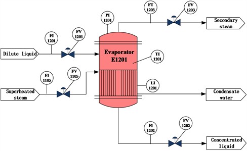
Temperature control is a crucial step in the evaporation production process. Therefore, ensuring that the temperature of the evaporator, TI1201, quickly and stably reaches the set value of 108±1 ℃ determines the quality of the finished product. When the temperature of the evaporator is too high, it will cause the liquid inside the evaporator to evaporate rapidly, leading to an increase in pressure. In order to ensure the stability inside the evaporator, the flow rate of superheated steam needs to be reduced until the internal temperature stabilizes. Conversely, when the temperature of the evaporator decreases, the evaporation rate inside the evaporator slows down. It is necessary to increase the flow rate of superheated steam to increase the product concentration and ensure the economic efficiency of the evaporator.
The evaporator equipment is a complex controlled object, and there are interconnections among its various controlled variables. Any change in any part will have an impact on the entire system. Thus, on the premise of ensuring the safety and economy of the production process of the evaporator control system, it is necessary to maintain the stability of key control variables, which are respectively: the internal pressure of the evaporator, PI1201, the liquid level of the evaporator, LI1201, and the outlet flow rate, FI1201.
3. Modeling and parameter identification of the evaporator temperature control system
3.1. Transfer function of the evaporator temperature control system model
In this experimental platform, the evaporator temperature affects the amount of material evaporation. Therefore, the stability of concentration depends on the temperature variation. To ensure concentration stability, it is necessary to maintain the stability of the evaporator temperature. With the system’s composition, structure, and physical laws known, its mathematical model is derived and established using mathematical formulas. According to a similar temperature control system in reference, during the heating process of the evaporator temperature control system, the heat flow generated by overheated steam heating dilute liquid is, causing the temperature of the dilute liquid to rise at a rate of :
where: represents the specific heat capacity coefficient of the dilute liquid, represents the temperature of the dilute liquid.
As the temperature of the dilute liquid increases, a temperature difference is formed with the external environment, and heat flow is dissipated to the outside:
Heat dissipation is proportional to temperature, that is:
where: represents the heat transfer coefficient.
Substituting Eq. (3) into Eq. (2), get:
The heat flow from superheated steam to the dilute liquid is equal to the heat dissipated by the superheated steam at that moment:
where: represents the heat dissipated at time , and represents the percentage efficiency of heat transfer to the evaporator at time .
Given the inertia delay of the entire evaporator device heating, the heat flow provided by the superheated steam to the dilute liquid at time is:
where: represents the delay time.
Substituting Eq. (6) into Eq. (4), obtain:
Rewrite Eq. (7) in the following standard form:
where: and represent the time constant and gain coefficient of the evaporator temperature control system model.
Performing Laplace transformation on Eq. (8):
So, neglecting some minor factors, the dynamic characteristic model of the relationship between the superheated steam flow rate and evaporator temperature can be approximated as a first-order inertia lag element. Its transfer function is given by:
3.2. Identification of system parameters using particle swarm optimization algorithm
The output exhibits an S-shaped curve change, as shown in Fig. 2.
Fig. 2The step curve of the evaporator temperature
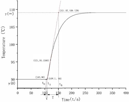
The calculation formula of the gain of the tangent method is as follows:
where, is the final steady-state value of the controlled variable, is the initial steady-state value of the controlled variable, and is the output change amplitude (i.e., the change amplitude of the given step function).
The sampling period of this experimental system is once per second, the initial temperature is 90 ℃, the heating steam valve is opened as a step input, after a period of time, the temperature finally stabilizes at 109.128 ℃, so the gain of this model is 1.9128, the time constant and lag time need to be determined by drawing a graph, draw a tangent at the inflection point of the curve, the intersection with the time axis is , and the intersection with the steady-state asymptote of the curve is , then the values of and can be obtained, as shown in the following formula:
As shown in Fig. 2, the valve opening change time is 104s, is 108.7s, is 151.07s, the coordinates of the curve inflection point are (121, 95.5506), and the tangent equation is:
The evaporator temperature system model obtained by the tangent line method is:
When using the tangent method to obtain the mathematical model, there are some drawbacks. Firstly, it achieves fitting by shifting the curve backward by time units relative to the corresponding curve, so it cannot perfectly fit into an S-shaped curve. Secondly, since the sampling time in this experiment is 1 second, the inflection points in the data may not necessarily be the true inflection points of the curve, which is related to the values of the time constant and the lag time τ. Therefore, an intelligent algorithm is adopted to optimize the parameters of the mathematical model and reduce the influence of human factors.
Principle of Particle Swarm Optimization Algorithm: In 1995, scholars Kennedy and Eberhart were inspired by modeling and simulating the foraging behavior of bird flocks [14]. By allowing each individual in the swarm to explore the objective and share information, the entire swarm can quickly obtain the optimal solution to the problem in the solution space.
Assuming there are particles, each particle changes its position as it iterates through the solution space, represented as and has a velocity , where . Each particle obtains its individual best solution and the swarm's best solution , after iterations. The velocity and position of the -th particle at step are given by Eq. (15) and (16) respectively:
where: is the velocity of the current -th particle, , are the individual learning factor and social learning factor respectively, is the position of the -th particle, represents the best position found by the current particle so far, represents the best position found by the entire swarm, , are random numbers between [0, 1].
Firstly, the first-order inertia and lag element is a frequency domain description. To describe the model obtained from identification in the time domain, Eq. (10) needs to be transformed through the inverse Laplace transform to obtain the differential equation:
where: is the temperature difference, is the valve opening difference, is the current time, is the time constant, is the amplification factor, and τ is the lag time.
Then, through iterative calculations, the predicted temperature value at each time point can be obtained. The functional expression is as follows:
where: represents the current temperature value at time , and represents the total time.
Finally, the mathematical function model obtained through particle swarm optimization algorithm identification is:
In the algorithm identification system of this experiment, the adopted fitness function is the Integral of Squared Error (ISE). This fitness function uses the squared value of the deviation, which can cancel out positive and negative deviations with each other. In this way, it emphasizes the focus on large deviations and is mainly used to suppress the occurrence of relatively large deviations during the process. Moreover, it is relatively convenient for mathematical processing, and its functional expression is:
where: is the deviation between the output of the identified model and the actual output of the system.
In order to reduce the randomness of the algorithm, multiple groups of identification experiments were carried out using the improved method proposed in this paper. Fifteen groups of data were randomly recorded, and the obtained value of the model fitness function (ISE) is 3.1556.
Fig. 3Comparison diagram of model data
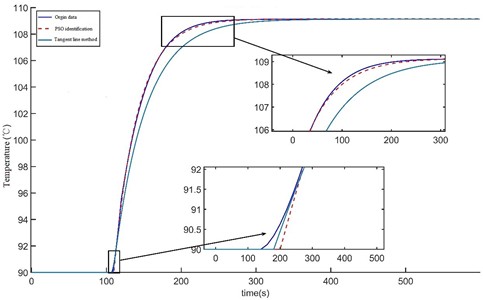
By importing the original data and the data of the models generated by the tangent method and the improved particle swarm optimization algorithm into MATLAB and calculating their fitting conditions using statistical parameters, as shown in Fig. 3, it can be seen that the parameter identification method based on the particle swarm optimization algorithm can basically achieve a complete fit with the original data through the calculation of these three statistical parameters. In contrast, the fitting degree of the tangent line method is far inferior to that of the parameter identification method based on the particle swarm optimization algorithm.
4. Design of VUF-PID controller
4.1. PID controller
The PID control algorithm is the most common control method in daily life, and its expression is shown in Eq. (22):
where: is the deviation between the set value of the system and the measured value of the controlled object, represents the controller output,  is the proportional coefficient, is the integral time constant, is the derivative time constant, and
  is the deviation.
4.2. VUF-PID controller
After the emergence of fuzzy control, due to the fixed structure of the fuzzy controller, its control rules and the universe of discourse cannot be adjusted in real - time according to the state of the control system. Thus, there are two disadvantages of fuzzy controllers:
1) Insufficient adaptability.
In the process of fuzzy PID control, once the values of quantization factors and proportional factors are determined, they cannot be easily changed. The selection of these factors has a decisive impact on the control quality of the entire system. At the same time, this will lead to a decrease in the adaptive ability of the control system when the system error exceeds the predefined target or when the environment changes. The initially established rules are no longer applicable, resulting in a decrease in the effectiveness of the controller.
2) Insufficient accuracy.
Fuzzy rules are established based on a fixed fuzzy universe of discourse. When the system experiences significant errors, there are multiple control rules that can handle them. As the control time increases and the error gradually decreases, the number of control rules also decreases, and the control effect deteriorates. Although increasing the number of fuzzy subset variables and control rule entries can optimize the response speed and control effect of the system, it also leads to a large number of control rules, making the implementation of fuzzy controllers more challenging. Furthermore, expanding the range of control rule values can also reduce the real-time nature of the control system, resulting in a larger steady-state error for fuzzy control.
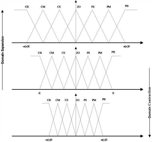
To address the above issues, Professor Li proposed the idea of VUF-PID algorithm in his paper [6]. This method introduces scaling factors to dynamically adjust the range of input and output universes of the fuzzy controller. The variable-universe concept expands the universe of discourse as the error increases and contracts it as the error decreases, while keeping the fuzzy rules unchanged. When the error is near zero, due to the compression of the universe of discourse, the number of control rules increases, improving the control accuracy. as shown in Fig. 4. The output variables of the variable-universe module are the input universe scaling factors and , and the output universe scaling factor of the fuzzy controller.
By multiplying the quantization factor by the scaling factor output from the variable universe module, the scaling of the fuzzy universe of discourse is achieved. This operation not only changes the range of the universe of discourse but also affects the membership functions of the fuzzy subsets. When the universe of discourse is compressed, the shape of the fuzzy subsets becomes sharper, and the number of rules near zero increases. This adjustment helps achieve fine - tuning of the system without changing the number of fuzzy subsets, and the total number of control rules remains unchanged. In other words, when the same fuzzy rules are applied to a smaller universe of discourse interval, it is equivalent to adding fuzzy rules to each output interval, thus increasing the relative number of rules in the system. When the universe of discourse is expanded, the entire graph is “stretched”, enabling the fuzzy controller to perform control over a larger range.
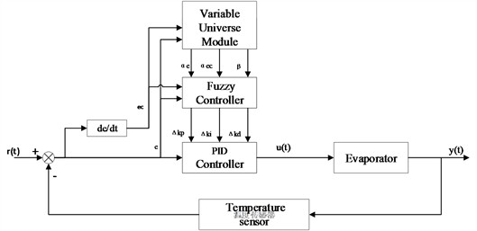
Fig. 4Principle of VUF-PID control system
When the quantization factor increases, the input universe of discourse of the fuzzy control is effectively compressed, and the number of control rules near zero increases. As a result, the system will respond more sensitively to smaller errors and error changes. When the proportionality factor increases, the output universe of discourse of the fuzzy control is expanded, the application range of the control rules becomes larger, and the adaptive range of the fuzzy PID controller for parameters is enhanced.
The input/output universes for error , error rate, and PID parameters (, , ) are normalized to the interval [−3, 3]. Both the input and output variables use 7-segment fuzzy linguistic values, and the fuzzy subsets are {NB, NM, NS, ZO, PS, PM, PB}. The triangular membership function is chosen as the membership function. This function is smoother in the transition region, enabling the triangular membership function to produce relatively continuous results during the processes of fuzzy inference and defuzzification. The fuzzy control rule table is shown in Table 1.
Single-loop Variable Universe Fuzzy PID (VUF-PID) controller consists of a variable-universe module and a fuzzy PID module. The variable-universe module generates input universe scaling factors and , as well as output universe scaling factor , based on the input errorand the rate of change of error. In the VUF-PID controller, while keeping the range of input and output universes and the number of fuzzy control rules unchanged, the quantization and proportionality factors are adjusted to achieve scaling control of the basic input and output universes. This generates a new rule base. Then, the fuzzy control adjusts the PID parameters online, thereby improving control quality. The control principle is illustrated in Fig. 5.
Table 1Fuzzy rule table
NB | NM | NS | ZO | PS | PM | PB | |
NB | PB/NB/PS | PB/NB/NS | PM/NM/NB | PM/NM/NB | PS/NS/NB | ZO/ZO/NM | ZO/ZO/PS |
NM | PB/NB/PS | PB/NB/NS | PM/NM/PB | PS/NS/NM | PS/NS/NM | ZO/ZO/NS | NS/ZO/ZO |
NS | PM/NB/ZO | PM/NM/NS | PM/NS/NM | PS/NS/NM | ZO/ZO/NS | NS/PS/NS | NS/PS/ZO |
ZO | PM/NM/NS | PB/MN/NS | PS/NS/NS | ZO/ZO/NS | NS/PS/NS | NM/PM/NS | NM/PM/ZO |
PS | PS/NM/ZO | PS/NS/ZO | ZO/ZO/ZO | NS/PS/ZO | NS/PS/ZO | NM/PM/ZO | NM/PB/ZO |
PM | PS/ZO/PB | ZO/ZO/PS | NS/PS/PS | NM/PS/PS | NM/PM/PS | NM/PS/NS | NB/PB/PB |
PB | ZO/ZO/PB | ZO/ZO/PM | NM/PS/PM | NM/PS/PM | NM/PM/PS | NB/PB/PS | NB/PB/PB |
Fig. 5Principle of VUF-PID control system
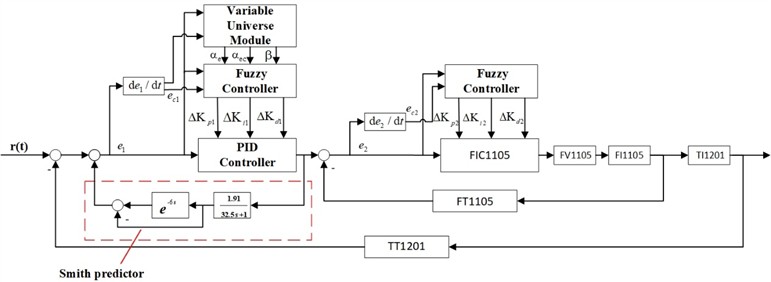
To achieve rapid and stable temperature control and maintain a specific temperature, a cascaded VUF-PID controller is designed by combining the VUF-PID controller with the cascade control scheme. Its structure is as follows: The main loop consists of a variable universe module, a fuzzy controller, and a PID controller. Its function is to control the evaporator temperature (TI1201) quickly and stably. The secondary loop is the fuzzy PID control of the superheated steam flow rate (FI1105). It consists of a fuzzy controller and a PID controller and aims to control the superheated steam flow rate and reduce the disturbances caused by the secondary loop. The structure of the cascaded control controller is shown in Fig. 6.
Fig. 6Cascaded VUF-PID temperature control structure diagram
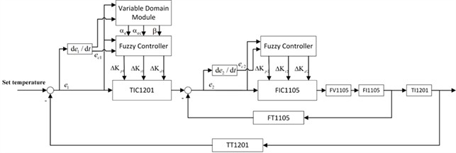
Both controllers use a two-input three-output fuzzy inference mechanism. The inputs of the evaporator temperature fuzzy controller and the variable universe module are the deviations between the evaporator setpoint and the actual temperature, as well as the rate of change of the deviation . The output of the variable universe module is the scaling factors (, 

 and
and  ) for quantifying the fuzzy controller’s quantization factor and proportion factor. By varying the scaling factors, the control range of the fuzzy controller is adjusted. The output of the fuzzy controller is the change in the proportional, integral, and derivative terms (, , ) of the evaporator temperature PID controller. The inputs of the fuzzy PID controller for the superheated steam flow rate are the deviation
  between the desired flow rate obtained from the evaporator temperature controller and the actual flow rate, as well as the rate of change of the deviation (). The output is the change in the proportional, integral, and derivative terms (, , ) of the superheated steam flow rate controller. In this structure, the PID controllers are traditional PID controllers that control the variables using fixed values. The fuzzy controller, on the other hand, achieves adaptive control by adjusting the correction values determined based on the deviation and rate of change of the deviation.
The cascade dual-mode fuzzy PID algorithm has two different control modes compared with the cascade fuzzy PID algorithm. These two modes can be switched according to the operating status of the system, control requirements, or other specific conditions. Through the switching of the two modes, both the response speed and control accuracy can be taken into account at different stages. When facing large disturbances or changes in the system state, it can quickly switch to the appropriate mode for effective control, thus having better dynamic performance and steady-state performance as a whole, especially performing more excellently when dealing with complex and changeable working conditions.
4.3. Smith-VUF-PID controller
The Smith predictor is a feedback control algorithm used in industrial process control and is commonly used in regulatory control systems. Its main purpose is to observe and predict the output signal of the process, providing an estimate of the process state, and making control decisions based on this estimate. In process control systems with pure time delays, the Smith predictor is a commonly used tool aimed at addressing the stability issues caused by the pure time delay. The control schematic diagram of the Smith predictor is shown in Fig. 7.
Fig. 7The control schematic diagram of the Smith predictor
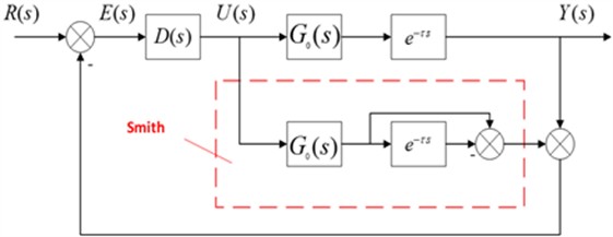
By using the Smith predictor for compensation, the pure time delay is moved outside of the closed-loop system, effectively eliminating its influence on the control system [15] and promoting stable operation and performance optimization. It is evident that the prerequisite for the Smith predictor to work is the establishment of an accurate mathematical model of the controlled object. After creating a Smith-VUF-PID controller, a cascade Smith-VUF-PID controller is established based on this controller. In the main loop, a Smith predictor consisting of a previously identified first-order inertia plus time delay model of the evaporator temperature control system is added, while keeping the secondary loop unchanged. This helps attenuate the impact of the time delay element on the entire system. The structure diagram of the cascade Smith-VUF-PID control is shown in Fig. 8.
5. Experimental results and analysis
5.1. Experimental setup
In order to test the control performance of the control algorithm for the closed-loop system, algorithm designers always need a semi-physical simulation experimental platform. The SMPT-1000 has established a temperature control system for the evaporator by simulating the actual engineering. In this study, by controlling the temperature control system of the evaporator on the SMPT-1000 experimental platform, the temperature curve data and other parameter curves can be obtained, which can be displayed on the same screen and operated on simultaneously. We implemented all control algorithms on the SIMATIC PCS7 V8.0 platform, and the evaporator project is deployed and set up on the SMPT-1000 device.
The temperature control system of the evaporator is mainly divided into five parts, namely the controller (operation station, S7-400 controller), ET-200 distributed I/O (interface module, ET-200M module), the actuator (double-effect valve, pump, fan, operation indicator light), the input device (measurement sensor, panel button) and the controlled system (SMPT-1000).
Fig. 8Cascaded Smith-VUF-PID temperature control structure diagram
5.2. Temperature control curve analysis
Based on the obtained mathematical model of the evaporator temperature, this paper constructs an evaporator temperature control system in the simulation software and conducts simulation experiments on each controller separately. The particle swarm optimization algorithm is used to optimize the parameters of the evaporator temperature control system built with the PID controller, and the optimal parameter values are selected according to the fitness function value. In this experiment, the Integral Time Absolute Error (ITAE) is used as the evaluation index of the controller for the fitness function [16], and the expression of the fitness function is shown in Eq. (23):
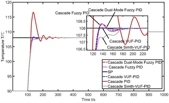
To demonstrate the superiority of the Cascade Smith-VUF-PID algorithm in controlling the evaporator temperature system, the temperature curve performance of the system under different control algorithms including Cascade Smith-VUF-PID, Cascade VUF-PID, Cascade Dual Mode Fuzzy PID, Cascade Fuzzy PID, and Cascade PID algorithms is compared.
The input of all controllers is the measured value of the evaporator temperature, and the output is the opening degree of valve FV1105. In addition, the PID parameters of each controller are kept consistent. , ,  represent the PID parameter values for the primary loop, while , ,
  represent the PID parameter values for the secondary loop. The parameter values for each algorithm are shown in Table 2.
As can be observed from Fig. 9 and Table 3, the conventional cascade PID control for regulating the evaporator temperature has a settling time of 160 s, a peak value of 116.633 ℃, an overshoot of 7.99 %, and it takes a long time to reach the steady-state. However, after using cascade fuzzy PID control and cascade dual-mode fuzzy PID control, the settling time is reduced to 127 s, the peak values are reduced to 108.323 ℃ and 108.296 ℃, and the overshoots are 0.29 % and 0.27 %, respectively. This indicates a significant improvement in the performance indicators of the evaporator temperature control system after introducing fuzzy control, with little difference between the dual fuzzy controller and single fuzzy controller. When using cascade VUF-PID control, the settling time is 124 s, the peak value is 108.021 ℃, and the overshoot is 0.019 %. Compared to traditional methods, the settling time is reduced by 36s, and the overshoot and peak value are greatly reduced. This demonstrates that the Smith-VUF-PID algorithm can greatly optimize the evaporator temperature control system when appropriate parameters are chosen. It not only improves control accuracy and enhances adaptive capability but also achieves similar performance to adding a fuzzy controller. When using cascade Smith-VUF-PID control, the peak value is almost identical to the setpoint, resulting in essentially zero overshoot. The settling time is 124 s, although it lags behind the other four algorithms in peak time. However, this method achieves a smooth transition to the setpoint without overshooting, demonstrating further improvement in control performance compared to the VUF-PID algorithm. Additionally, the results are consistent with the simulation results. Due to the inclusion of the Smith predictor, the characteristics obtained from the Smith-VUF-PID control in the evaporator temperature control system are generally excellent.
Table 2Parameters and ranges for the four algorithms
Algorithms | Parameter Values |
Cascade PID | 0.85, , , , |
Cascade fuzzy PID | 0.85, , , , , [0.25, 1.45], [17.38, 17.62], [0.4, 1.6] |
Cascade dual-mode fuzzy PID | 0.85, , , , , [0.25, 1.45], [17.38, 17.62], [0.4, 1.6], [1.6, 2.8], [4.88, 5.12] |
Cascade variable universe fuzzy PID | 0.85, , , , , [0.25, 1.45], [17.38, 17.62], [0.4, 1.6], [1.6, 2.8], [4.88, 5.12], [0.5, 1.2], [0, 1.2], [0.68, 1.0] |
Table 3Parameters and ranges for the four algorithms
(s) | Peak (℃) | (s) | Overshoot / % | |
PID | 137 | 116.633 | 160 | 7.99 |
Fuzzy PID | 138 | 108.323 | 127 | 0.29 |
Dual-Mode Fuzzy PID | 139 | 108.296 | 127 | 0.27 |
VUF-PID | 137 | 108.021 | 124 | 0.019 |
Smith-VUF-PID | 180 | 108.004 | 124 | 0.0037 |
Fig. 9Scenarios of the SMPT-1000 device
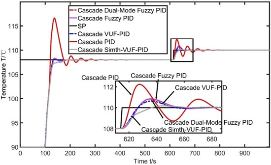
In order to further validate the superiority of the Smith-VUF-PID controller, two types of disturbances were selected in this paper. The first disturbance was an increase in the setpoint temperature load at 615 s, and the second disturbance was an increase in the opening of the secondary steam valve “FV1203” at 610s. First, from the temperature load increase curve in Fig. 10 and the performance indicators of each algorithm after the load increase in Table 4, it can be observed that the settling time of the evaporator temperature control system using conventional cascade PID control is 88 s, with a peak value of 112.236 ℃ and an overshoot of 2.03 %. However, after using cascade fuzzy PID control and cascade dual-mode fuzzy PID control, the settling time is reduced to 72 s, the peak values are reduced to 110.855 ℃ and 110.826 ℃, and the overshoots are 0.78 % and 0.75 %, respectively. This once again confirms that the inclusion of a fuzzy controller improves system performance, and also verifies that there is not much difference between the dual fuzzy controller and single fuzzy controller. When using VUF-PID control, the settling time is further reduced to 55 s, with a peak value of 110.639 ℃ and an overshoot of 0.58 %. Compared to using fuzzy control, this algorithm improves the static characteristics of the evaporator temperature control system but still has room for optimization. Finally, when using cascade Smith-VUF PID control, the settling time is further reduced to 48 s, with a peak value of 110.173 ℃ and an overshoot of 0.15 %. Compared to conventional cascade PID control, the settling time is almost halved, and the overshoot is reduced by 1.88 %. Although small overshoots are still present due to disturbances, Smith-VUF-PID control further optimizes the control accuracy of the evaporator temperature control system and achieves good robustness compared to the other four algorithms.
Table 4Performance indicators of the four algorithms during an increase in temperature load
(s) | Peak (℃) | (s) | Overshoot /% | Ess (℃) | |
PID | 13 | 112.36 | 88 | 2.03 | 0.027 |
Fuzzy PID | 21 | 110.855 | 72 | 0.78 | 0.003 |
Dual-Mode Fuzzy PID | 21 | 110.826 | 67 | 0.75 | 0.003 |
VUF-PID | 21 | 110.639 | 55 | 0.58 | 0.003 |
Smith-VUF-PID | 28 | 110.173 | 48 | 0.15 | 0.002 |
Fig. 10The temperature control curve for increasing the setpoint temperature load
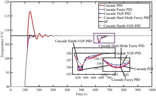
According to the curve chart of increasing the opening of the secondary steam valve in Fig. 11 and the performance indicators after the increase in Table 5, it can be seen that when the opening of the secondary steam valve increases, the settling time of the evaporator temperature control system using conventional cascade PID control is 25 s. The temperature of the evaporator drops to a maximum of 105.531 ℃, and the peak time is 16 s. When using cascade fuzzy PID control and cascade dual-mode fuzzy PID control, the settling time is 23 s and 24 s, respectively, and the temperature of the evaporator drops to a maximum of 105.619 ℃ and 105.645 ℃. The peak time for both algorithms is 16 s. From the data, it can be seen that the overall performance indicators do not improve significantly when fuzzy controllers are added to deal with this disturbance source. When using cascade VUF-PID control, the settling time is 20 s, and the temperature of the evaporator drops to a maximum of 105.831 ℃. The peak time is 16 s. Although the peak time is not significantly improved compared to the previous three algorithms, the remaining characteristic indicators are optimized. When using cascade Smith-VUF-PID control, the settling time is 0 s, and the temperature of the evaporator drops to a maximum of 106.308 ℃. The peak time is 20 s. Both the Smith-VUF-PID algorithm and the other four algorithms experience temperature fluctuations when subjected to this disturbance. However, according to the calculation method of settling time (±2 % of the final value), it can be considered as 0 s. The Smith-VUF-PID control algorithm exhibits smaller temperature fluctuations and faster recovery speed in the face of this disturbance. Compared to the VUF-PID control algorithm, this algorithm achieves no overshoot and smoother transition to the setpoint in temperature adjustment when facing disturbances, thereby increasing the stability of the control system.
Table 5Performance indicators of the four algorithms during an increase in the opening of the secondary steam valve
(s) | Peak (℃) | (s) | Ess (℃) | |
PID | 16 | 105.531 | 25 | 0.006 |
Fuzzy PID | 16 | 105.619 | 23 | 0.003 |
Dual-Mode Fuzzy PID | 16 | 105.645 | 24 | 0.003 |
VUF-PID | 16 | 105.831 | 20 | 0.003 |
Smith-VUF-PID | 20 | 106.308 | 0 | 0.003 |
Fig. 11The temperature control curve for increasing the opening of the secondary steam valve
6. Conclusions
This article uses a variable-universe fuzzy PID controller to control the temperature of the evaporator system. This controller improves the performance indicators and disturbance rejection of the control system, but it does not achieve the desired results due to the limitations of fuzzy rules. When using a VUF-PID controller, the scaling factor is obtained through the input error and its rate of change. The scaling factor is used to modify the quantization factor and proportional factor of the fuzzy controller, effectively scaling the fuzzy rules. This controller enables the system to have faster settling time, smaller overshoot, increased adaptability, and higher control accuracy. When using a Smith-VUF-PID controller, a Smith predictor is added to eliminate the influence of pure time delay on the system. Based on the VUF-PID controller, this controller essentially eliminates the overshoot of the evaporator temperature control system and can quickly mitigate the impact of disturbances on the system. Although it lags behind in peak time, it is because the controller stabilizes the system when reaching the peak. Compared to other conventional control algorithms, the Smith-VUF-PID control algorithm demonstrates superiority in controlling the evaporator temperature system, indicating its potential for practical applications.
References
-
F. Xun and Y. Xun, “Design of evaporator control system based on PCS7 and SMPT-1000,” Journal of Electronic Design Engineering, Vol. 25, No. 15, pp. 113–116, 2017.
-
J. Sun, D. Zhang, Q. Huang, L. Tian, and T. Cheng, “Design of temperature control system for evaporator based on cascade fuzzy self-adaptive PID method,” (in Chinese), Journal of The Chinese Journal of Process Engineering, Vol. 23, No. 9, pp. 1290–1299, 2023, https://doi.org/10.12034/j.issn.1009-606x.222320
-
L. Dang, “Temperature Control method for the metal heat treatment process based on variable universe fuzzy PID,” (in Chinese), Techniques of Automation and Applications, Vol. 43, No. 1, pp. 14–17, 2024, https://doi.org/10.20033/j.1003-7241.(2024)01-0014-05
-
Y. Wang, M. Wei, X. Hu, M. Jiang, and L. Zhang, “Research on variable universe fuzzy PID control strategy of pipe lining induction heating system,” Modelling and Simulation in Engineering, Vol. 2020, pp. 1–9, Dec. 2020, https://doi.org/10.1155/2020/8852943
-
B. Wei, F. Tang, C. Liang, and A. Zhang, “An aviation Tu-rntable control system based on a variable universe fuzzy proportion integral differential (PID),” (in Chinese), Journal of Beijing University of Chemical, Vol. 49, No. 2, p. 107, 2022, https://doi.org/10.13543/j.bhxbzr.2022.02.013
-
G. Zhu, G. Shi, Z. Hou, and Y. Wang, “Research on variable universe fuzzy PID for position control system of moving workbench,” Journal of Modern Manuacturing Engineering, No. 1, pp. 119–124, 2022, https://doi.org/0.16731/j.cnki.1671-3133.2022.01.017
-
W. Jiang, G. Liu, T. Wang, and K. Gao, “Variable universe fuzzy PID contrlol based on adaptive contracting expanding factors,” (in Chinese), Journal of Engineering Mechanics, Vol. 38, No. 11, pp. 23–32, 2021, https://doi.org/10.6052/j.issn.1000-4750.2020.11.0786
-
H. Li, “Temperature control of beer fermentation based on variable domain fuzzy PID and neural network technology and its application analysis,” Advanced Control for Applications, Vol. 6, No. 3, pp. 203–203, Mar. 2024, https://doi.org/10.1002/adc2.203
-
Q. Jiang, W. Zeng, T. Yu, J. Xie, and L. Chen, “Core power control of liquid molten salt reactor based on variable universe fuzzy-PID,” (in Chinese), Journal of Nuclear Power Engineering, Vol. 41, No. 2, pp. 109–113, 2020, https://doi.org/10.13832/j.jnpe.2020.02.0109
-
M. Huang and P. Li., “Research on variable universe fuzzy PID control of electronic shaft driving gravure printing system,” Journal of Electric Drive, Vol. 49, No. 12, pp. 77–81, 2019, https://doi.org/10.19457/j.1001-2095.dqcd18983
-
B. Dai, Z. Zhou, Chen, and Y. Li, “3-DOF helicopter control based on variable universe fuzzy PID,” Journal of Control Engineering of China, Vol. 26, No. 11, pp. 2061–2066, 2019, https://doi.org/10.14107/j.cnki.kzgc.170626
-
J. Liu, C. Wang, S. Qiu, and L. Dong, “Variable universe fuzzy control of once-through steam generator feedwater,” Annals of Nuclear Energy, Vol. 207, p. 110699, Nov. 2024, https://doi.org/10.1016/j.anucene.2024.110699
-
Z. Wang and F. Luo, “Control system design of evaporator based on PCS7 and SMPT-1000,” IEEE 3rd Advanced Information Technology, Electronic and Automation Control Conference (IAEAC), pp. 1723–1727, Oct. 2018, https://doi.org/10.1109/iaeac.2018.8577897
-
J. Kennedy and R. Eberhart, “Particle swarm optimization,” in ICNN’95 – International Conference on Neural Networks, Vol. 4, pp. 1942–1948, Jul. 2025, https://doi.org/10.1109/icnn.1995.488968
-
Y. Yao, Z. Zhang, J. Shi, and R. Liang, “Research on post-rolling cooling system temperature control based on smith-fuzzy PID,” Journal of Materials, Processing and Design, Vol. 8, No. 2, Jan. 2024, https://doi.org/10.23977/jmpd.2024.080211
-
J. Zhu and Y. Tian, “Research on PID parameter optimization based on improved particle swarm optimization algorithm,” Journal of Jilin Institute of Chemical Technology, Vol. 40, No. 5, pp. 34–39, 2023, https://doi.org/10.16039/j.cnki.cn22-1249.2023.05.007
About this article

This work was supported by the Jilin province science and technology development item (YDZJ202201ZYTS555).
The datasets generated during and/or analyzed during the current study are available from the corresponding author on reasonable request.
Jianjun Zhu: supervision, project administration, conceptualization, writing-review and editing. Binghong Wei: methodology, software, visualization, writing-original draft preparation. Yingqi Huang: methodology, formal analysis, writing-original draft preparation. Ye Tian: data curation, formal analysis, investigation, writing-original draft preparation.
The authors declare that they have no conflict of interest.
